

Introduction: 2 Pieces Arcade Set


We are 3 robotics students of the University of Seville that wanted to approach arcade games in an unusual way. Arcade cabinets are always huge bulks that cannot be moved that easily so we came up with a comfy solution to pair with a classic arcade bartop, allowing you to have an awesome retro-style controller left anywhere on the house that can work with another Raspberry Pi as a gamepad without loosing the ability to play on a propper arcade cabinet. This way, we are combining the best parts from both worlds, ensuring lots of fun!
Supplies
MATERIALS
10 mm MDF planks
Paint
Acrylic sheet
Screws and nuts
Brackets
Wood filler
2 players Arcade kit
XY C15H 20Wx2 audio amplifier
2x 4Ω 10W speakers
WS2812B LED strip
2 10k Ω resistors
1 220 Ω resistor
1 100 µF capacitor
Buttons or switches
1 infrared LED
IR receiver
Raspberry Pi 3B+
Raspberry Pi Zero
Arduino UNO
ATX power supply (ours came from an old computer)
LCD monitor
HDMI or VGA cable (and converter if needed)
2x USB cable
2x Micro SD card
Wii remote
EQUIPMENT
CNC machine
Nail gun
Crimping tool
Jigsaw
Drill
Screwdrivers
Brushes
Tin soldering iron
USB keyboard
Mini HDMI adapter
Working computer
Micro SD to USB or micro SD to SD adapter
Software
Fusion360
ArduinoIDE
Octoprint
Raspberry Pi Imager
Putty or another SSH client
Step 1: Designing the Tabletop


We started with a piece of paper drawing some sketches of the tabletop, locating the buttons and joystick. We went with this design, seeking comfort by using a cushion below.
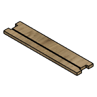
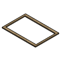
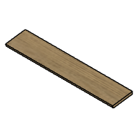
It has 6 wood pieces in total: 2 long planks, 2 short planks, 1 bottom panel and 1 top board. Files are attached below with some photos.
Conjunto Completo


Step 2: Designing the Bartop


As on the previous step, we began by drawing sketches of how we imagined the bartop. After some time arguing and a bit of work on Fusion 360 we came up with this. Even though the marquee appears on this design as MDF, we went with some acrylic sheets instead
Estructura completa
Attachments


Step 3: Building the Tabletop


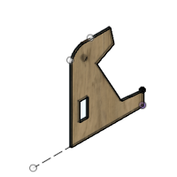
The final model of the tabletop consists in a base that uses 4 planks that fit one into another. Between them there is a wood pannel to hold the electronic components and a Raspberry. Over the base there is a large wood board which holds all the buttons and the joystick for the tabletop. To get the pieces well finished we used a CNC with the fusion's sketchs. Here you can see some pictures of the process. All the pieces have been primed and painted white.
To join the pieces of the board, we used a nail gun to securely hold the structure. However, the control panel has been attached with a hinge so that it can be opened to examine all the components in case of any issues. Holes have been made in order to hold the electronics in place. Wood filler was applied later to hide these holes from the outside
Step 4: Building the Bartop


Firstly, we divided all the boards into different pieces using squares and rulers. Afterwards, we cut them using a jigsaw and drilled some holes for the brackets. After much effort, all the pieces were obtained separately. We also made some room for the fan, the plug, and the switch on the back of the bartop, as well as a door in order to retrieve the coins inserted and be able to access the inside of the machine. For this purpose, this door is locked with a mailbox lock.
After cutting and preparing all the pieces, we primed each one to later paint them white. After allowing them to dry for some time, we assembled them. For this, we used brackets on the sides of the pieces, except for the bottom board, where we used glue instead due to the difficulty of tightening the nuts with the machine assembled, as this had to be the final piece.
To position the screen and frame it within the previously made frame, we have added a new wooden board behind the monitor, using the VESA mount to securely attach it to the entire structure.
Step 5: Raspberry Pi
Firstly, we will prepare both the SD cards although for the Raspberry running Retropie an external USB storage device is strongly encouraged. Install a Raspberry Pi OS Lite on the SD card for the Zero and Retropie for the 3B+ using an adapter and the Raspberry Pi Imager software.
Setting the Pi Zero
Enable SSH and Wi-Fi or use an external USB keyboard and display on the first boot. After setting the SSH client and wireless conection, use your computer to SSH into it using Putty or another software. Get your Pi up to date by typing sudo apt update and sudo apt upgrade. This should be done pretty regularly
The Raspberry Pi zero will work as a network-available USB hub, offering any USB connection it has to another client. This will be done by using the USBIP utility. Although it may not be very difficult, what we'll be doing is not really begginer-friendly and having some kind of experience with the Linux terminal will help you a lot. That being said, I will try to make it as easy as possible so anyone can give it a try.
First of all, we will type sudo passwd root and it will ask you for the password. This way, we won't have the need to constantly type sudo while we work on this Pi. Given the fact that this Pi (server) will offer its USB devices through the network for any device to take, this mentioned device (client) must be able to know where to look for this USB server. For this purpose, we will need the Pi Zero IP. This matter would be solved if not for the fact that modern routers use the DHCP protocol where the Pi's IP will change over time. This can be bypassed with very different approaches. You can disable this directly on your router or using this other method.
We move on to the USBIP itself. Type "su -" and then the password you set before. Now you are superuser and there's no need to type sudo on almost every command.
Install USBIP with "apt install usbip" and load the host with "modprobe usbip_host". This must be done on every boot of our Pi, so now run "nano /etc/moudles". By inserting on the list "usbip_host", we are making sure it loads everytime.
Plug in the USB device you want to share and type in "usbip list -l". It will list the avaliable USB devices on your Pi. You should see the device ID (XXXX:XXXX). Write it down for later
Note: Debugging might play a really important role on this task. You can type "usbip help" for more info about the parameters of the command
We are going to make 2 scripts on this Pi, one for binding the USB device and one for unbinding it. Type nano /usr/sbin/usbip_start.sh and copy this, being XXXX:XXXX the device ID:
#!/bin/bash
usb1='XXXX:XXXX'
/usr/sbin/usbip bind --$(/usr/sbin/usbip list -p -l | grep '#usbid='$usb1'#' | cut '-d#' -f1)
Make this executable by typing chmod +x /usr/sbin/usbip_start.sh
Same process with the stop script: nano /usr/sbin/usbip_stop.sh and then:
#!/bin/bash
usb1='XXXX:XXXX'
/usr/sbin/usbip unbind --$(/usr/sbin/usbip list -p -l | grep '#usbid='$usb1'#' | cut '-d#' -f1)
Then chmod +x /usr/sbin/usbip_stop.sh
This way, we can now offer the USB device to a client with this two scripts. Let's make a python file with nano /home/sync.py and copy this:
import subprocess
from gpiozero import Button
from signal import pause
def start_usb():
subprocess.run(['/usr/sbin/usbip_start.sh'])
def stop_usb():
subprocess.run(['/usr/sbin/usbip_stop.sh'])
button = Button(2)
button.when_pressed = stop_usb
button.when_released = start_usb
pause()
Now type nano /etc/rc.local and add the following line: nohup python3 /home/sync.py &
At this point, the Raspberry Pi Zero should be prepared for the project
Setting the Pi 3B+
We move on to the other Raspberry Pi. In this case, it will be running Retropie but it will also act as an USBIP client. Set the root account again, update it and install USBIP like on the other one.
Type modprobe vhci-hcd and add the module on /etc/modules with nano. We are now going to create the other 2 scripts that will attach and detach the USB devices on the other Pi.
Repeat the process but change the content of the files to:
#!/bin/bash
server1='YYY.YYY.YYY.YYY'
usb1='XXXX:XXXX'
/usr/sbin/usbip attach -r $server1 -b $(/usr/sbin/usbip list -r $server1 | grep$
and
#!/bin/bash
/usr/sbin/usbip detach --port=$(/usr/sbin/usbip port | grep '<Port in Use>' | s$
with XXXX:XXXX and YYY.YYY.YYY.YYY being the USB device ID and the Pi Zero chosen IP address.
Now create the same Python file of the other Raspberry and add it to /etc/rc.local with nohup python3 /home/sync.py &
At this point, your Raspberries should be able to share the USB connection wirelessly. Doing that is as easy as pressing the sync buttons on both the tabletop and the bartop, as shown on the video.
Aditional settings
Powering up the Raspberry and the monitor at the same time will create some problems. Type sudo nano /boot/config.txt and add the lines hdmi_force_hotplug=1 and depending on your monitor, you should change the lines hdmi_group and hdmi_mode. More info on that here.
Force 3.5 mm audio jack output instead of HDMI by typing sudo raspi-config and moving over the GUI.
Using the Wii controller
Install MoltenGamepad following this guide. Setting the Wiimote as a wireless gamepad is pretty easy when using just buttons. However, the funny part about Wiimotes is that you can use their sensors to play games that require you to point at things. This makes them the most available yet not perfect Lightgun for emulating purposes.
You could make your life easier by just buying this kind of bars as they are really easy to work with and pretty much plug and play. But that wasn't our case as we wanted to squeeze every capability of the Wiimote by itself. Keep in mind the result may not be perfect but it's still really funny to play with.
Create a MoltenGamepad profile and bind the buttons with these aditional lines:
wiimote.wm_ir_x = (abs_x)
wiimote.wm_ir_y = (abs_y)
or
wiimote.(wm_home,wm_ir_x,wm_b) = calibratable(abs_x)
wiimote.(wm_home,wm_ir_y,wm_b) = calibratable(abs_y)
Then you would have to bind the controller to Retropie and hope for the best. More info here
Step 6: Coin Acceptor
First of all, the HX-916 has 5 differents terminals. Two of them are labeled as counters and won't be used in this project, a DC 12V, a coin signal and obviously a ground. Yellow wires on the ATX power supply carry 12V while black wires are GND.
To set up the machine we need to use the buttons that are installed in the HX-916:
1º Choose how many different coins are going to be used (6 in our case)
2º Select the number of impulses per type of coin. You should not worry that much on this step as this will be interpreted later by the arduino
3º Choose how many samples will be inserted (You should use at least 15 of every kind)
4º Set the accuracy (we chose 8)
5º Finally you must fit all the samples that you chose in the previous step for each type of coin
Here's a video for a more detailed guide.
The Arduino keeps track of all the money that enters the machine, stores this even when powering it off and shows it on the display. Pressing a designated button will reset this value to 0 in order to retrieve the money. Through code we will set the threshold for what is considered an in-game credit and a signal will be sent to the Raspberry.
In this case we are considering 50 cents a try. This way, inserting a 50 cents coin as well as various coins adding up to 50 cents will trigger the signal. On the other hand, 1€ and 2€ coins will trigger it 2 and 4 times respectively. Moreover, as an easter egg, "25 pesetas" coins, also known as "5 duros", former currency of Spain, will be accepted because that's how much it cost back in the day
Note: Arduino will only send one signal when reaching the threshold. Retropie itself won't acknowledge it unless it is already in a game. Inserted credits on a game shall be used before leaving as they will just disappear otherwise.
Step 7: Arduino

The code consists of 4 different elements: the IR receiver, the LED strip, the OLED display, and the coin acceptor. For this, we will use some Arduino libraries. After installing them, run the IRremote example ReceiverDemo, open the serial monitor and use an IR device (old TV remotes will work) to find the addresses of the buttons you want to use.
The Arduino board takes care of both the coin acceptor and the LED strip. One of the inputs is Coin signal from the coin acceptor. It recognizes the number of pulses and, therefore, the type of coin inserted. Depending on the coin type, its respective quantity is added to two variables: total_amount and total_amount_game. In the first variable, the total number of coins historically inserted into the machine is recorded. This variable can be reset by pressing the ON button of the IR remote used.
On the other hand, total_amount_game is the variable responsible of sending the coin signal to the Raspberry Pi when the total reaches 50 cents. Then, by wiring it up accordingly to the board, it will work like a button, triggering the in-game coin button.
An IR receiver is used to control the LEDs. Depending on the button pressed on the remote control, the lights turn on in different colours. To determine the amount of money in the cash box, the total_amount variable is displayed on an OLED screen. However, this screen will only light up when pressing the button.
Attachments
Step 8: Setting Up the Electronics


DISCLAIMER: Working with mains voltage is pretty dangerous and you should avoid it if you don't really know what you are doing. You could always leave room for a power strip and use power supplies for every component needed
All the electrical circuits used in the bartop come from an old ATX computer power supply. We had to prepare the power supply for this project by desoldering both the switch and the socket. Solder neutral and ground of the LCD monitor directly to the socket and live wire should pass the switch as the one from the power supply. This way, the monitor and the power supply are powered up by mains voltage and can be controlled using the switch that comes with the power supply.
Due to the location of the power supply and the devices that use its power, we made use of some homemade PCB to power everything up. We made 2 of these to distribute both 5V and 12V, on top of the one that holds all the electronics that involve the Arduino. In the video attached to this step you can see this board working.
The previously mentioned boards will power up with 5V the tiny IR emitter, the WS2812b LED strip, the Raspberry, and the Arduino through Vin. It is crucial not to plug the Arduino under any circumstances via USB, as being powered from both sources would damage the Arduino.
Additionally, 12V will be given to the amplifier board that will drive the speakers, This amplifier is connected to the Raspberry Pi via the 3.5 mm audio jack. The other 12V needed in our case went to a bunch of LEDs from a broken LED tube in order to light up the marquee. We used them because we had them lying around, although you could just use the WS2812b LED strip.
Mount all the buttons and joysticks and attach them to the USB board and then to the Raspberry. Linking buttons will be wired directly to the Raspberry GPIO2 and ground, as mentioned previously.
Cut the USB wire and solder it thourgh the hole of the tabletop in order to make it look nicer. Another micro-usb connector was used to power up the Raspberry Pi 3+ although you can use the pins on the header.
Step 9: Decorating


To decorate the arcade machine, we chose to use stickers inspired by classic arcade games, such as Space Invaders, Pac-Man and Mario Bros. The stickers have been distributed both on the bartop and the tabletop, achieving a better visual appeal for the machines. The marquee was also printed as a sticker
Step 10: Enjoy

Grand Prize in the
Arcade Student Design Challenge


