

Introduction: 3D Printed Coin Shuffleboard


Table Shuffleboard is a game of skill common in North America. Similar to Curling, the object of the game is to slide the puck into zones near the end of the table to score points. This 3D printed coin launcher is the perfect portable shuffleboard game. Use pocket change as a puck and get a game going with friends on any table.
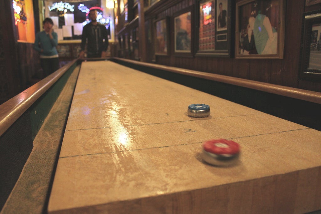
The typical tabletop shuffleboard setup has a polished surface dusted with slippery beads. The pucks glide smoothly across and require precise control. This version isn't as fancy, but the whole game fits in your pocket and can be played on any table that's handy.
Step 1: Tools + Materials

- Fusion 360
- 3D Printer
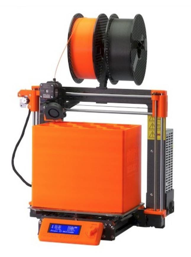
I use a Prusa I3Mk3S for just about everything. It's the best bang for your buck, in my opinion- very well made, 3D printable replacement parts, accurate and reliable.

- 3D Print Filament
- I used generic PLA for this project.
- Rubber Band
- Any American coin
Fusion 360 is free and it's awesome. I use it for everything I design and fabricate.
Student / Educator License (renew free every 3 years)
Hobbyist / Startup (renew free yearly)
Here's a link to the Fusion 360 model. It's parametric, so you can adjust the size by entering the width of any rubber band you may have handy.
Follow along with this Instructable to model your own!
Step 2: Video Tutorial
This video explains the entire modeling process. The rest of the Instructable explains the process with text and images, and goes into detail about 3D printing settings.
Step 3: Coin Launching Cup
The coin cup is the part that holds a coin in place and launches it by way of a rubber band.
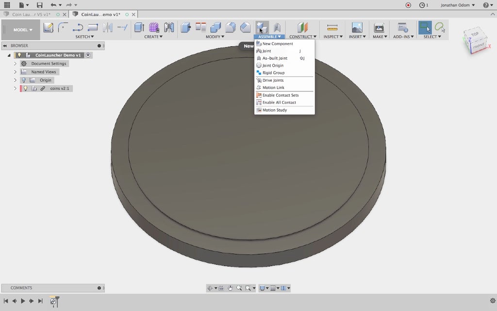
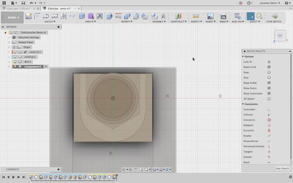
I started with a model of all the common American coins. In this screenshot you can see the nickel (the thickest coin) and the quarter (the one with the biggest diameter), but the penny and dime are there as well. I made one file with all the coins to get a sense of what I should design that could launch them all.
The Fusion archive of the coin design is attached in this step. Download it, then click "Upload" in the browser in Fusion to bring it in.
As always, I start a New Component to keep the model organized.
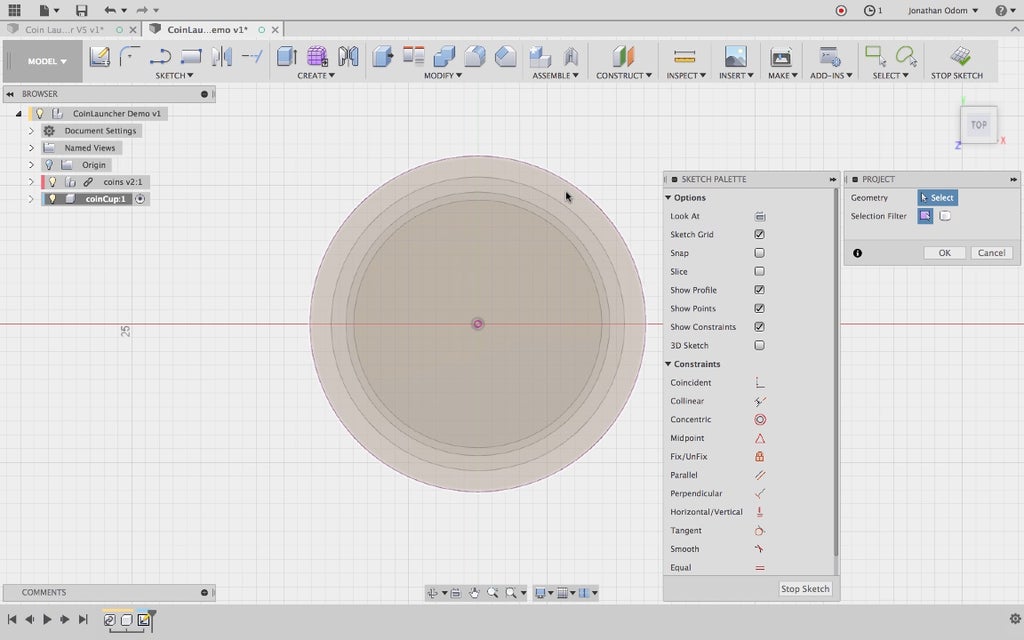
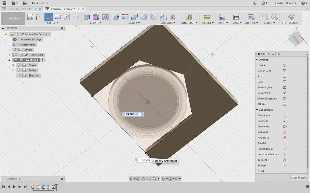
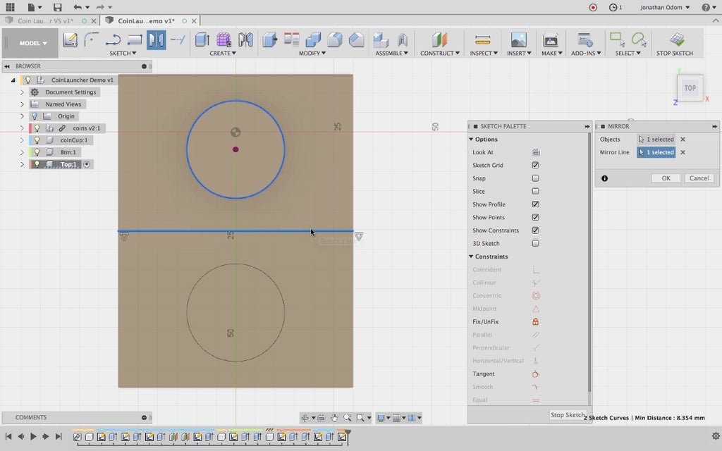
I create a sketch on the XY origin plane, then Project/Include > Project, selecting the quarter to project that geometry in plan. This will give me a line I can use to design the cup.
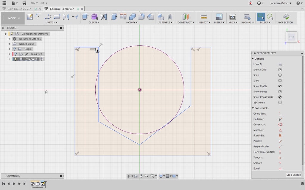
I figured the best way to ensure that any of the coins would fall into the cup centered would be to make a pocket with a "V" shaped profile- that way any coin will fall into the center when the launcher is tilted up.
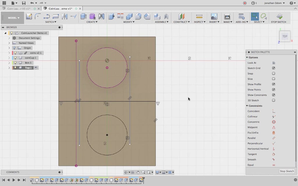
I draw a rough outline of the shape of the pocket, I'll make constraints and dimensions on the sketch later.
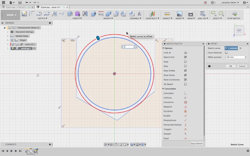
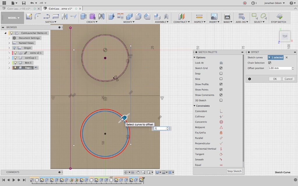
The quarter is the biggest coin and I want to make sure it doesn't get stuck in the pocket, so I offset the perimeter of the circle by .5mm.
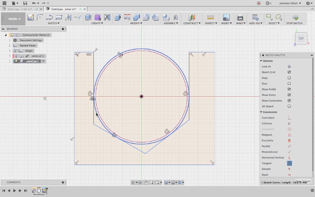
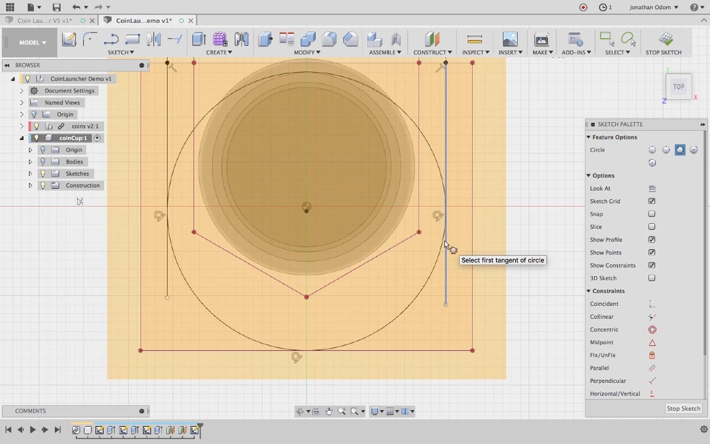
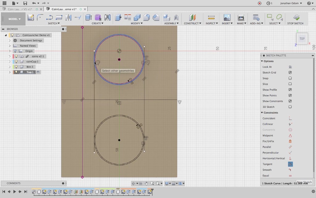
I use that offset circle to make all the lines tangent to it. In the Sketch Palette, I select Tangent and click all the straight lines on the inside followed by the circle. This makes all the lines stick to the circle.
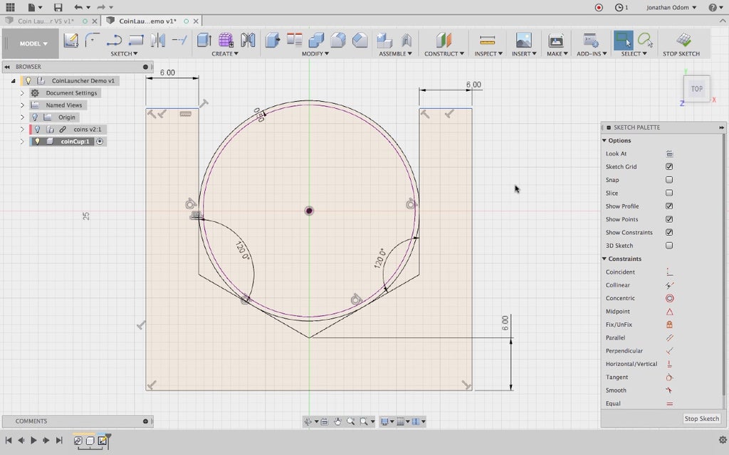
I use the Sketch>Dimension tool to make rational dimensions for all the features here. 120º for each side of the angled cup seems to make sense. Everything else is parallel at a depth of 6mm, which I think will give us enough to work with.
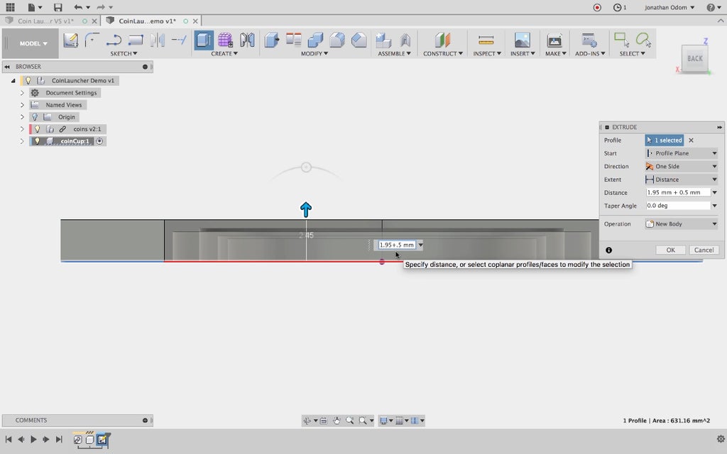
With that profile done, I select Create > Extrude and extrude that profile so that it meets the top of the nickel. That gives me 1.95mm, so I add another .5mm to that to make sure the nickel doesn't get stuck.
I create another sketch on the underside of the body I just made, closing the open part with a line. This gives me a rectangle I can use to give the coin cup some depth that is linked to the body I just made. That means that if I change the original extrusion, this sketch will automatically change.
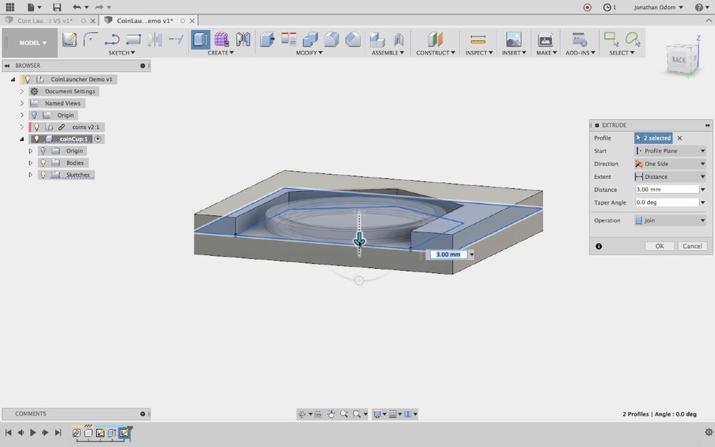
Create > Extrude gives me a rectangular floor for the cup. I make that 3mm, which is a solid dimension for an FDM 3D printed part.
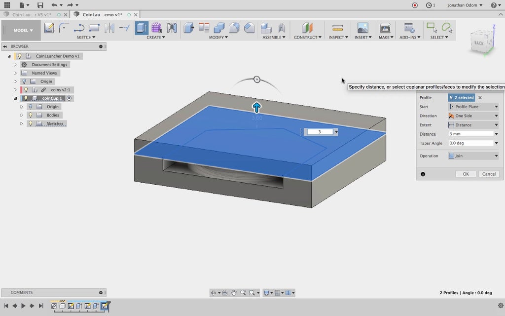
I repeat this step on the top of the cup, making that feature 3mm thick as well.
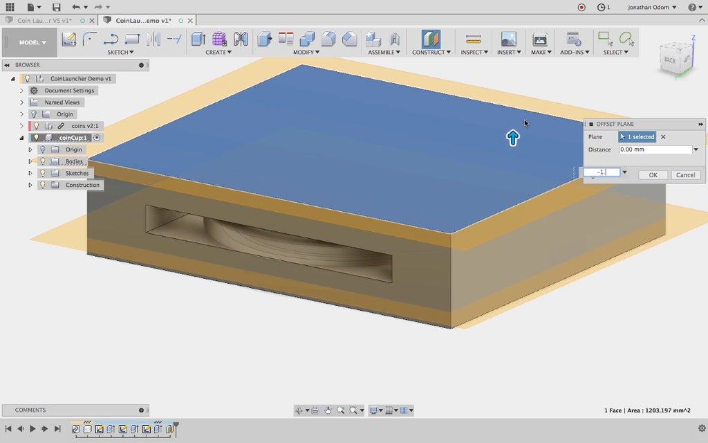
Now I need a chase around the cup to guide the rubber band. To make this feature, I offset a plane from the top and one from the bottom, both at 1.5mm. I find this dimension to be about the minimum I can do with an FDM printer without the part breaking under stress.
Creating a sketch on one of these new planes, I project the profiles of the inside and outside of the cup. Then I bisect the side walls and add ad 3-tangent circle to give myself some profiles I can use.
I use this shape to Extrude (Operation: Cut) this shape from one of the new planes to the other. This gives me a chase for the rubber band.

Step 4: Base With Parametric Controls
This model is parametric!
That means that its shape will automatically change to work with a rubber band of any length. Rubber bands come in so many shapes and sizes, and they break so easily, I thought it would make sense to be able to easily change one value (width of rubber band) and watch the shape of the launcher update to work with it.
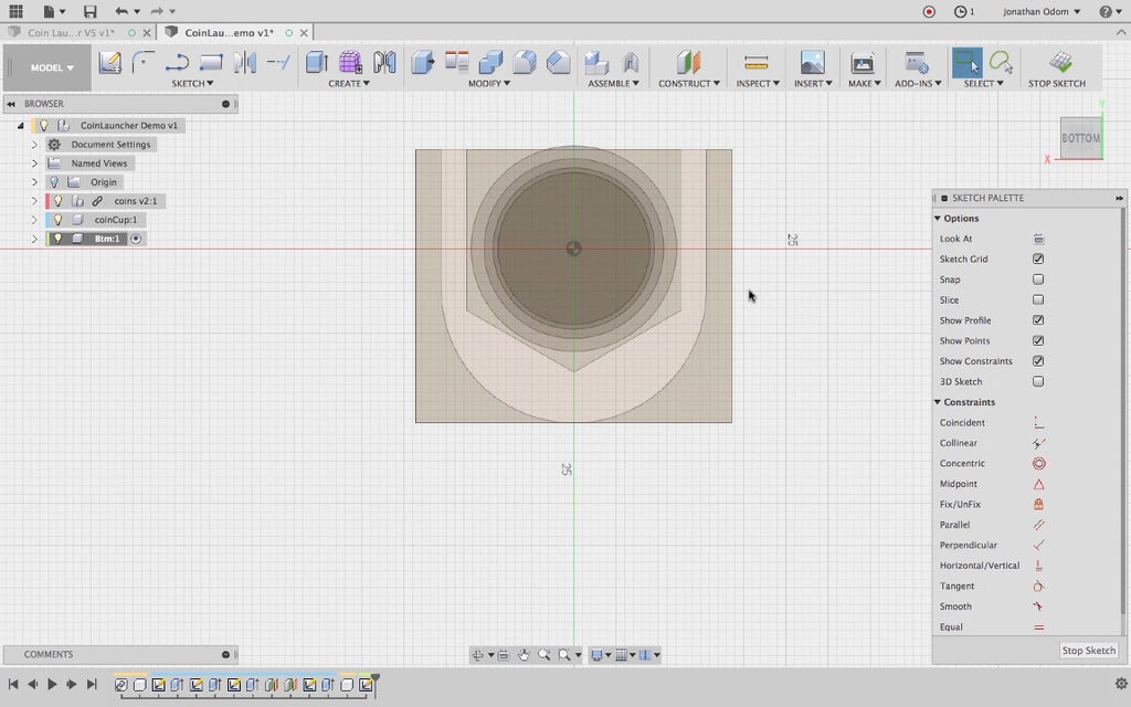
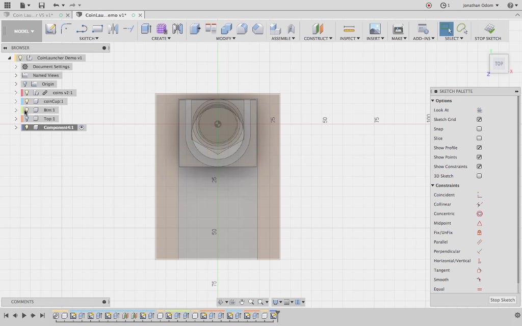
First, I create a new component, then make a sketch using the bottom of the coin cup as the reference plane (you can click on any flat face and make a sketch out of it). The face will automatically be projected if you do it that way, but it's very faint graphically so you might not notice it.
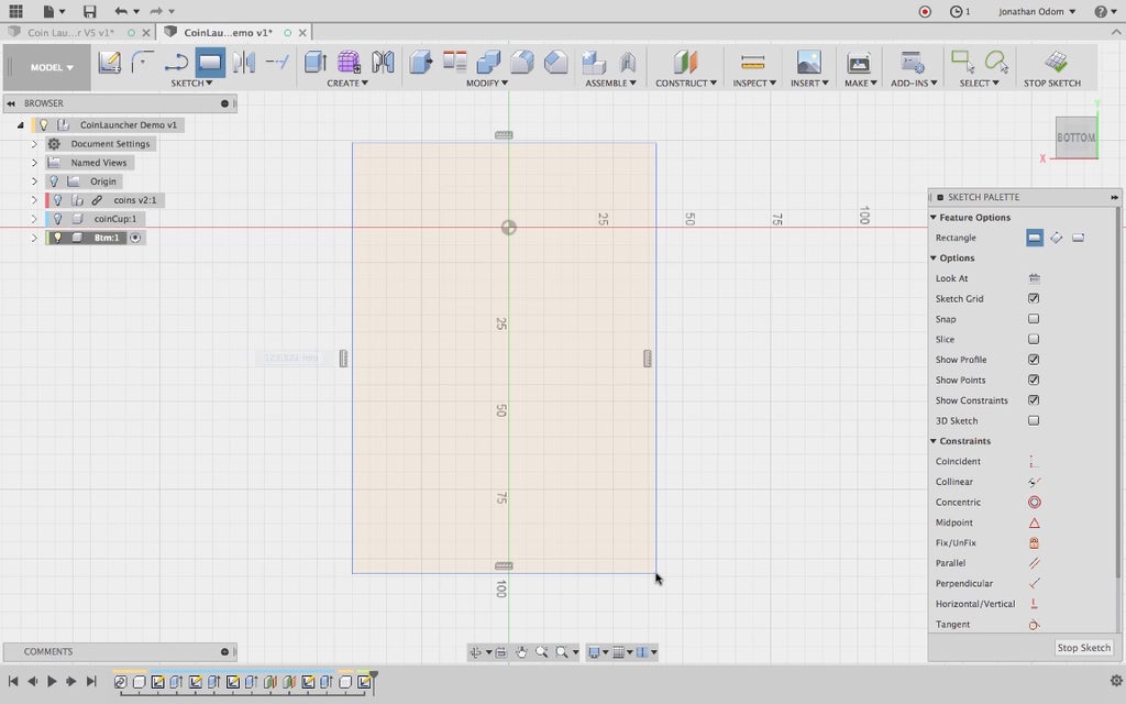
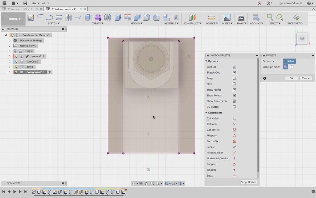
As usual, a rough outline of the thing I want to make will suffice: a bigger rectangle with the origin plane roughly in the middle.
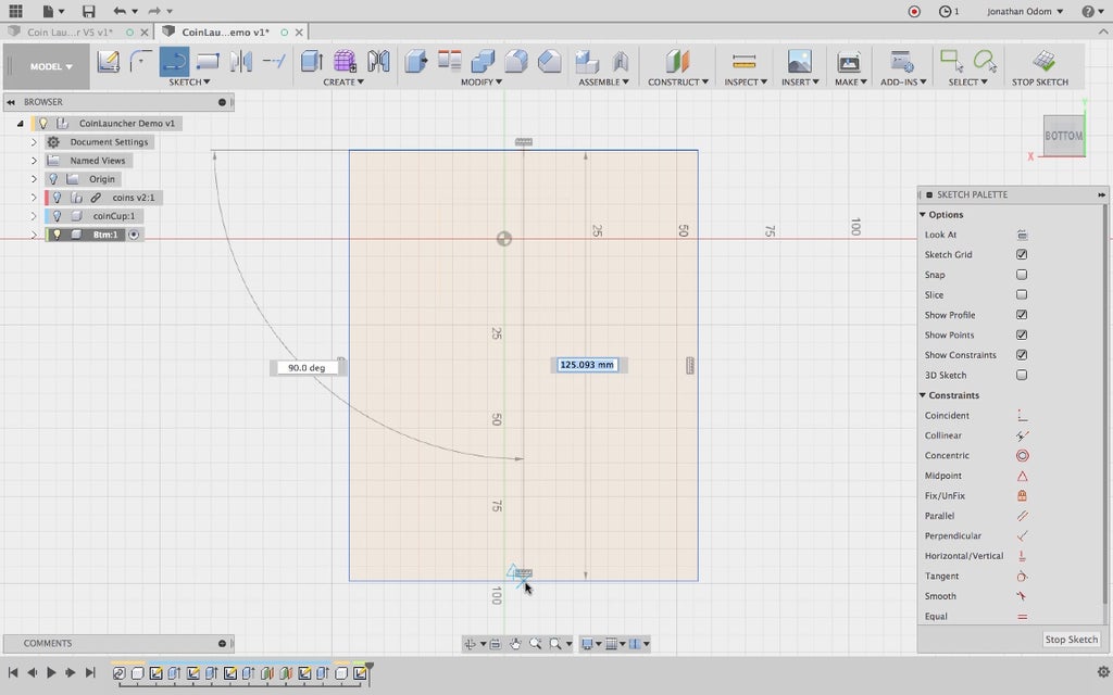
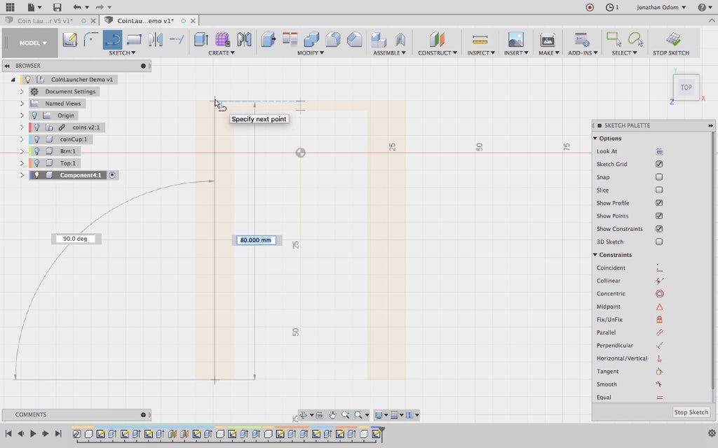
To properly control the rectangle using my parameters (coming later) I'm going to need a centerline. I draw a Line from the midpoint of the top line to the midpoint of the bottom line. I know I'm on the midpoint because the cursor snaps to the middle of the line and a blue triangle icon shows up.
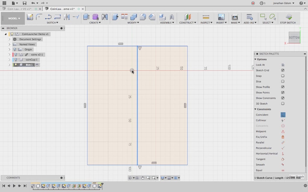
I want this parametric rectangle to stay centered on the coin cup, so I go to Sketch Palette > Coincident and click the centerline I just drew followed by the sketch origin point. This constrains the centerline to the center of the coin cup part.
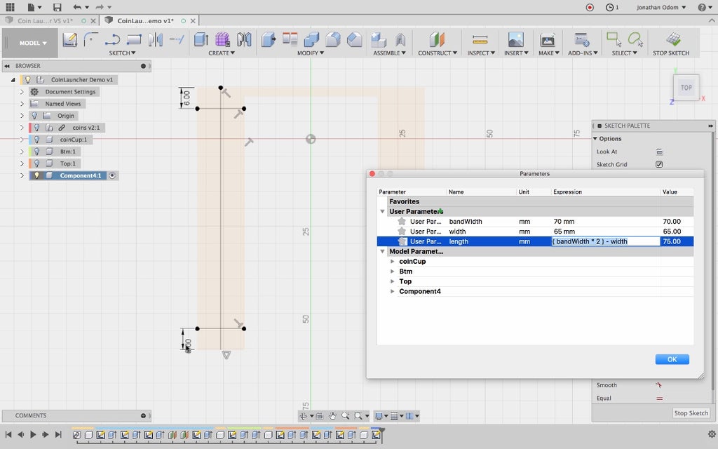
Now it's time to make parameters!
Here's what I know:
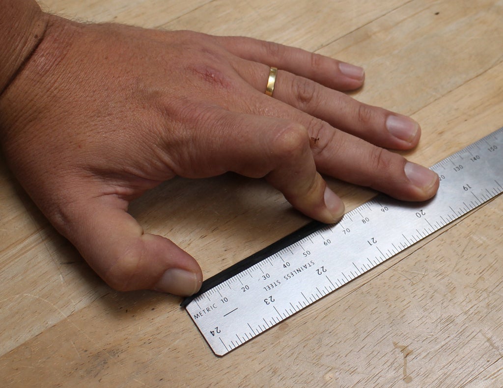
I can measure the rubber band easily by pressing it down and holding a ruler up to it. The one in the picture is 70mm long when folded in half.
To make the base a reasonable size, I need the sum of the length and width to equal the total length of the rubber band (the circumference if you think of it as a circle). So...
base length = ((measured rubber band length) * 2) - base width
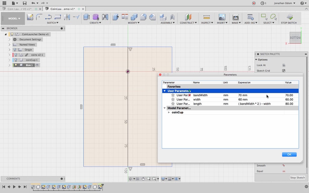
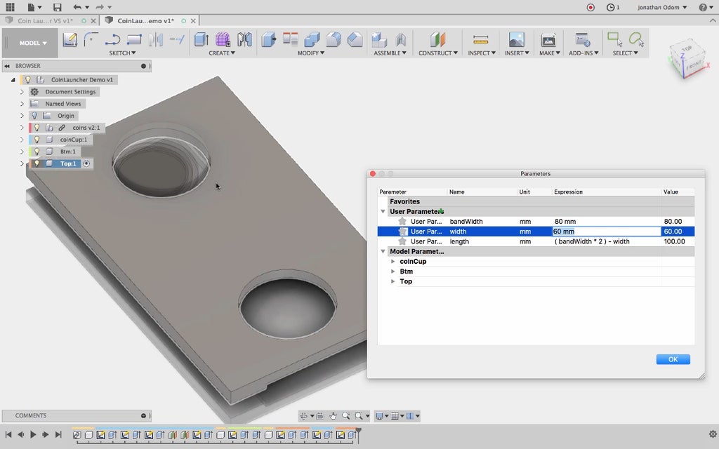
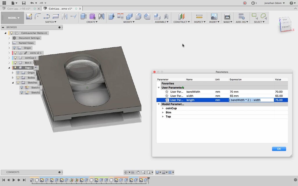
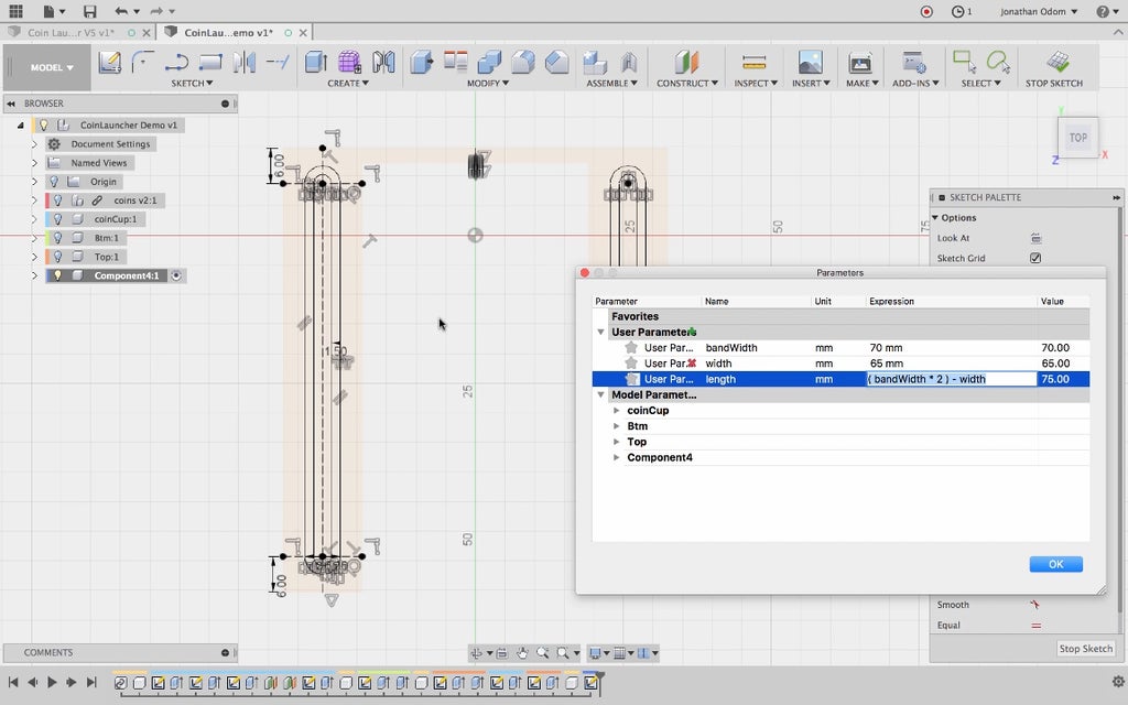
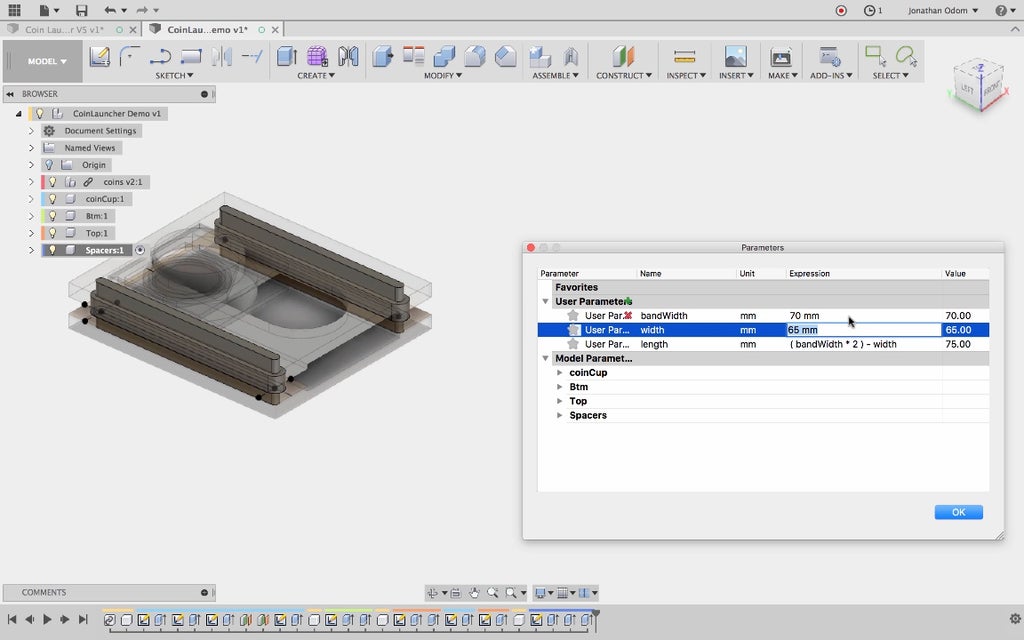
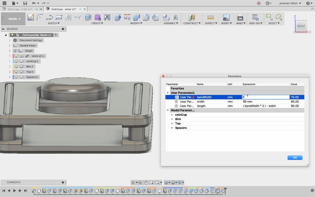
To make these parameters, I go to Modify > Change Parameters and click the green + to create new user parameters:
- bandWidth = measured width of rubber band
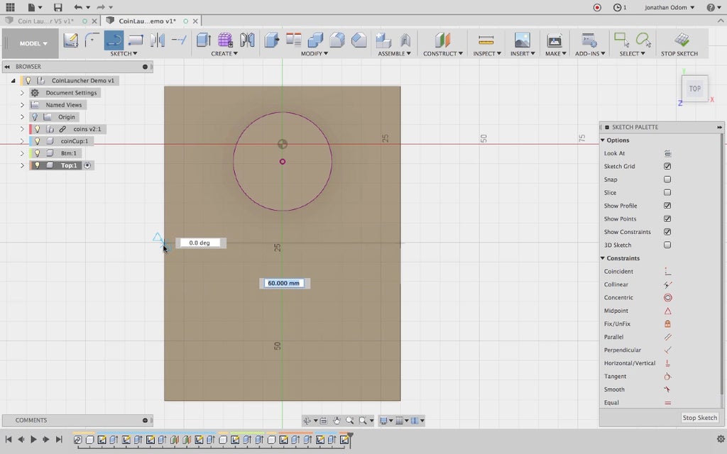
- width = preferred width of base. 60mm is a good size.
- length = (bandWidth * 2) - width
With these parameters in place, I'll be able to instantly update the model to fit with whatever rubber band I might have.
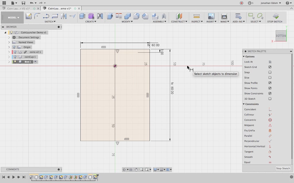
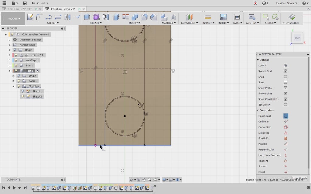
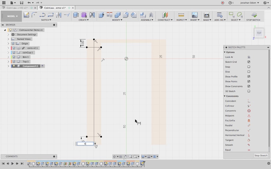
To set these dimensions, I just go to Sketch > Dimension, then click on the two vertical lines and set "width" as that value, then the two horizontal lines and set "length" as that value. I know these dimensions are set to parameters because there's and "fx: " preceding the number.
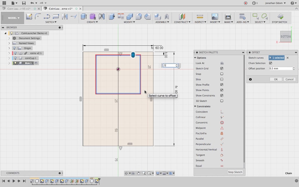
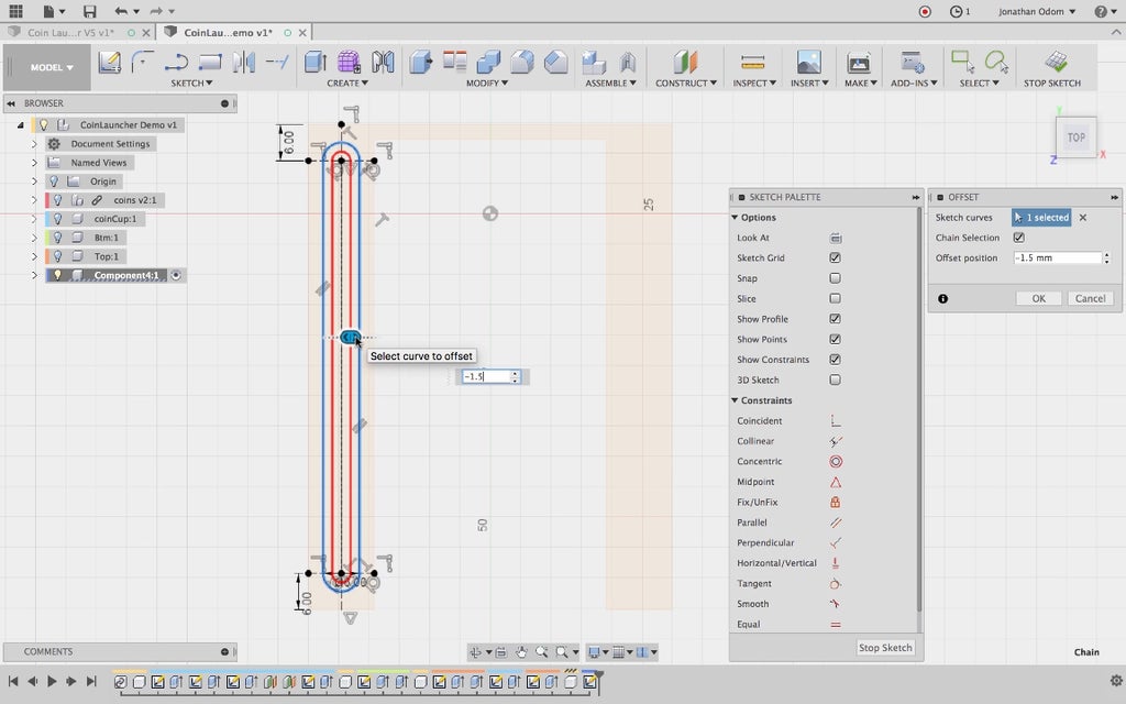
Now I need to draw the track for the coin cup, so I offset the rectangle linked to the coin cup by +.5mm.
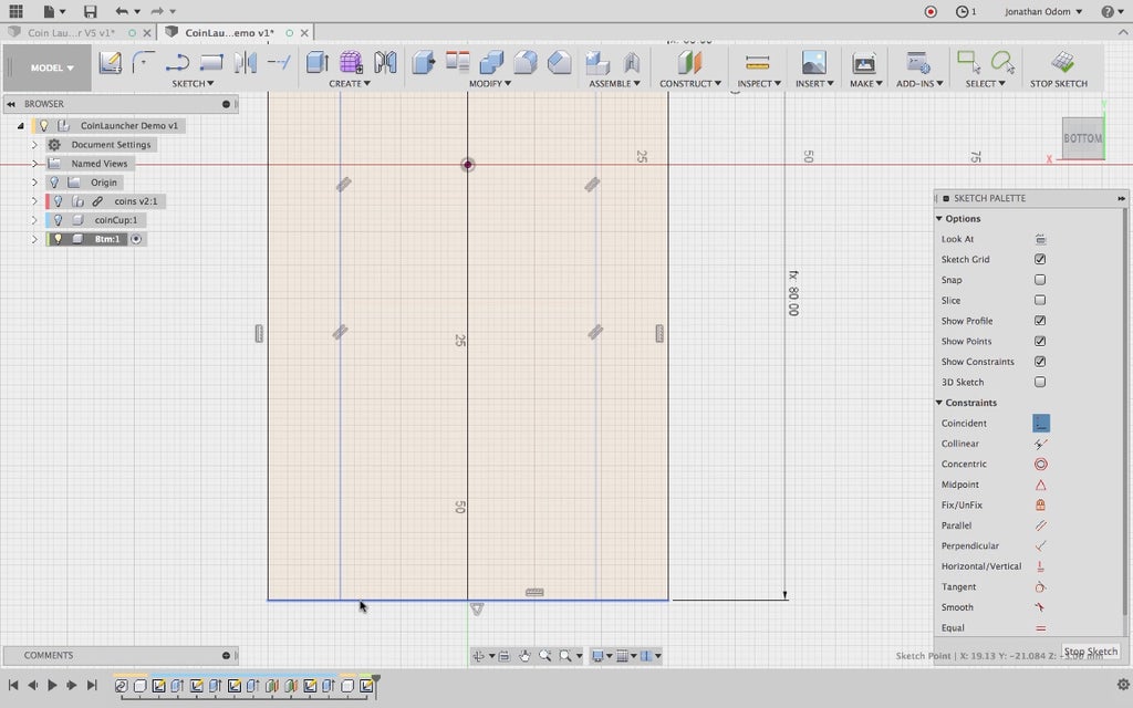
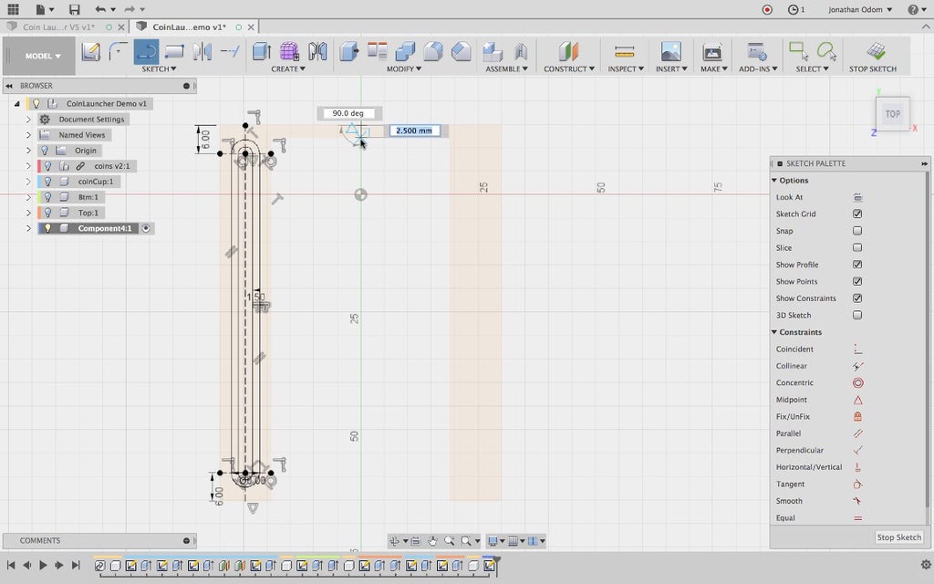
I delete the bottom line (I won't need it) and go to Sketch > Extend to make the chase go the whole length of the bottom part. The distance from the front edge of the coin cup to the front edge of the bottom part is set to 3mm.
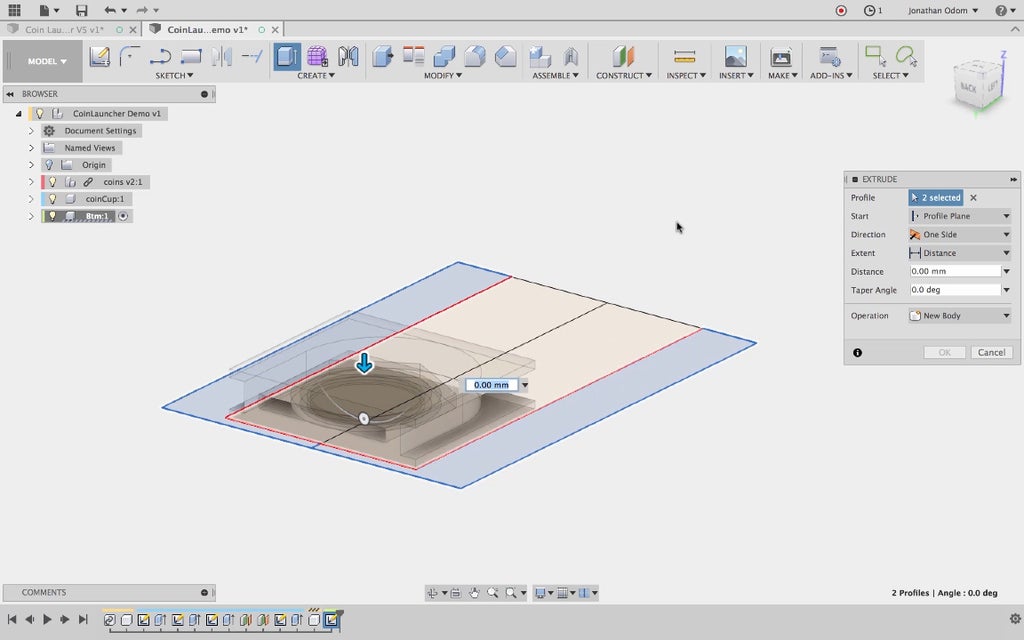
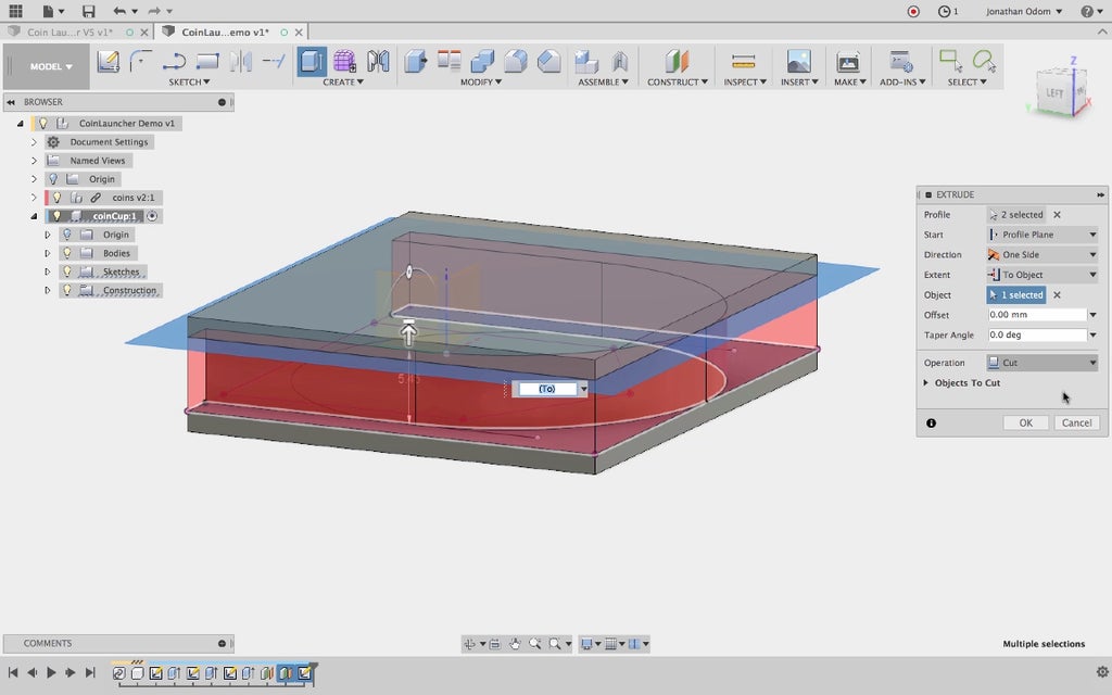
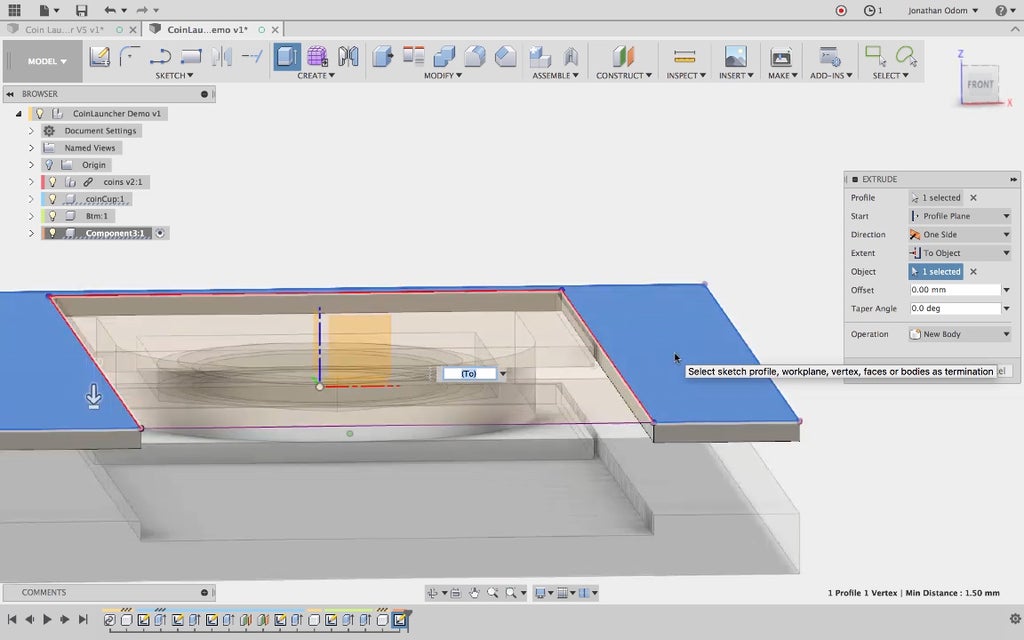
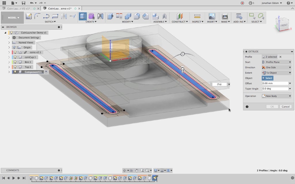
Next, I select these two profiles and extrude them up.
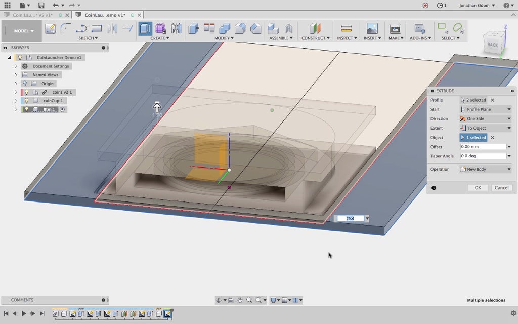
This thickness comes from setting Extent to To Object and selecting the top of the lower platform of the cup. This is more or less arbitrary, but this thickness must be less than or equal to the height of the coin cup pocket.
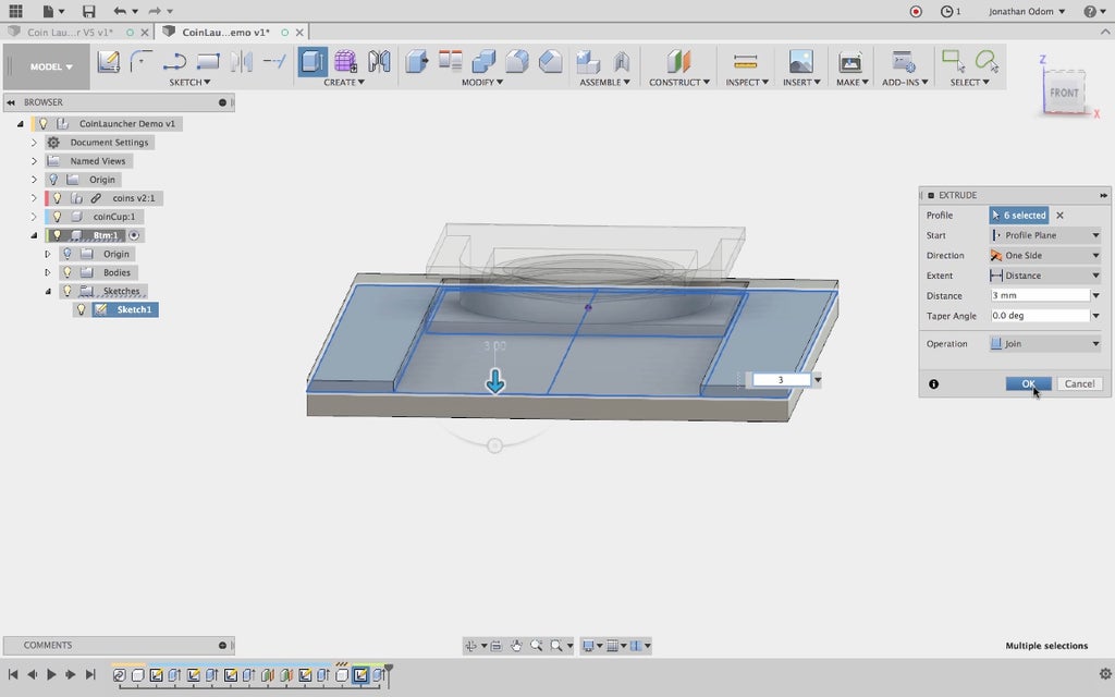
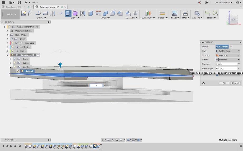
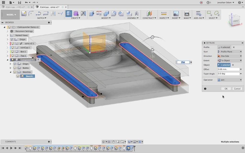
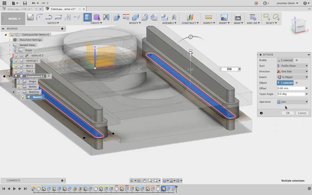
I turn on the sketch again in the Browser, then extrude all the profiles that make up the rectangular perimeter by 3mm. This gives me a flat base with a recessed track.
Step 5: Top With Pull Slot
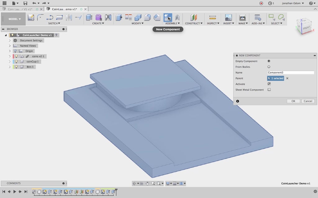
To make the top, I create a new component.
I make a sketch on the top face of the coin cup to start the top.
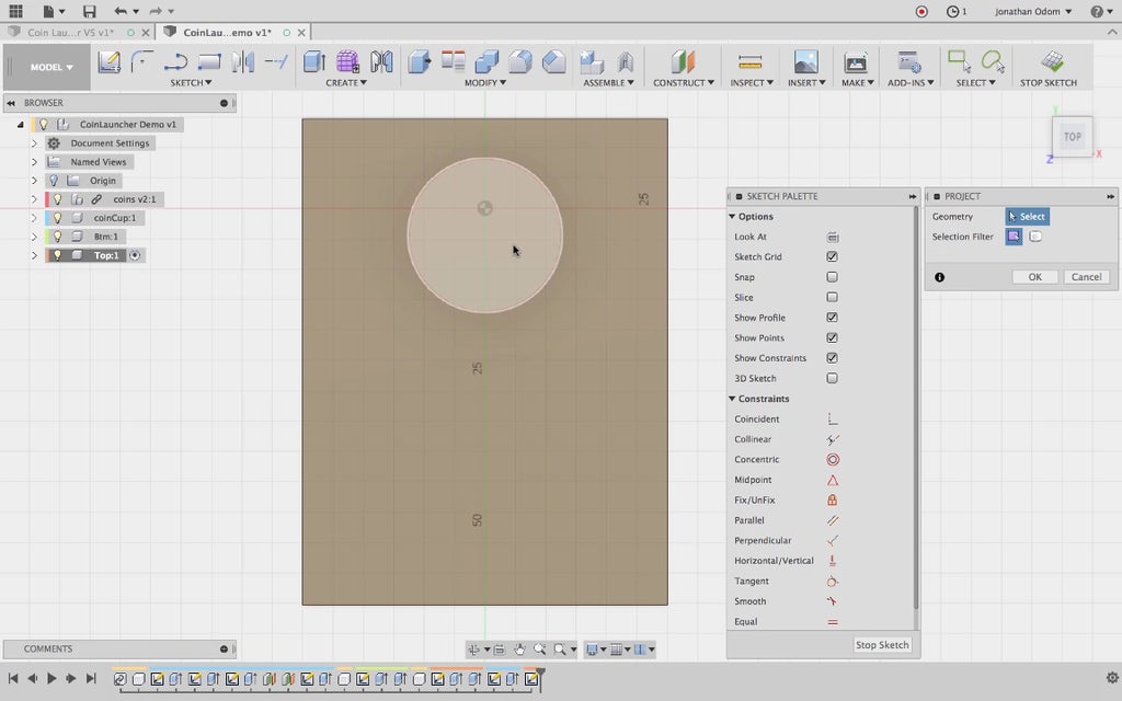
I got to Sketch > Project and click on the track and upper face of the bottom part. This will ensure that the size of the top part stays consistent with the bottom since the sketches will be linked.
Pro Tip: you know sketch lines are linked when the lines and nodes are pink.
Staying consistent with the geometry on the bottom, I extrude the outer face using To Object and clicking the under side of the coin cup chase.
I use the same sketch to extrude the flat solid feature on the top part by 3mm.
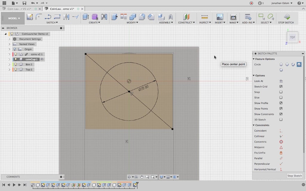
Activating the coin cup component (right-click > activate in the Browser), I create a sketch on the top of the coin cup, then draw a diagonal line from corner to corner to give myself a midpoint. I draw a Circle on this midpoint. 25mm will be a comfortable diameter for a knob that's used to pull back and release the cup.
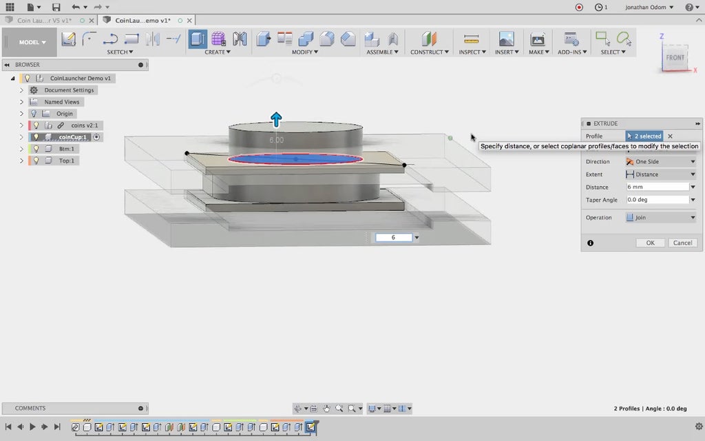
I extrude this feature by 6mm, giving myself enough of a protrusion that it's easy to grip with my thumb.
I activate the top component, then create a Sketch for the slot I'll cut out of it. I Project the face of the coin cup knob as a starting point.
I give myself a centerline between the midpoints of the vertical lines of the rectangle.
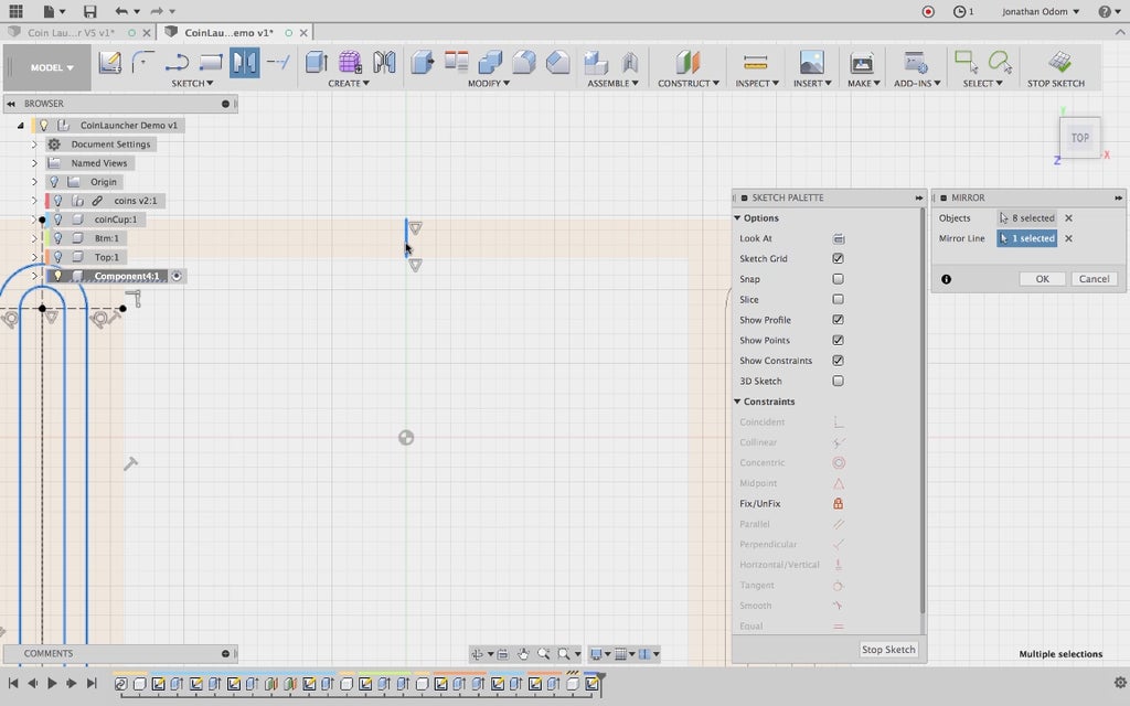
I use this centerline as the Mirror Line as I use Sketch > Mirror to mirror the circle about the center of the rectangle. This will ensure that the circle moves if the dimensions change.
I draw two vertical lines that will serve as the sides of the slot.
Since the slot needs to be slightly bigger than the diameter of the knob, I offset both of these circles by .5mm.
I use the Tangent constraint to constrain these two lines to the outer circles.
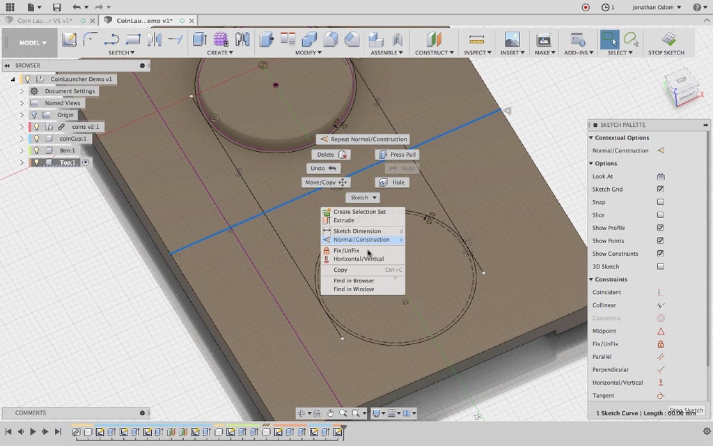
I turn the inner circles and centerline into Construction lines by right-clicking and selecting it from the menu. This keeps the number of profiles I'll need to select to a minimum.
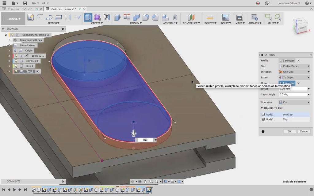
I Create > Extrude the profiles of the slot using To Object to make the extrusion stick to the upper face of the track.
Testing the parameters (always a good idea any time you make something new!), I see that the center part of the slot feature disappears. What could be the problem?
As I edit the sketch, I see that the vertical lines don't change their length when the length of the rectangle changes. I use a Coincident constraint to constrain the end points of these lines to the horizontal lines.
This solves the problem, as I can see through changing the parameters as a test.
Step 6: Spacers

To make the spacer parts, I make a new Component then create a Sketch using the upper face of the bottom part as the reference plane.
I bisect the left arm of this part by making a vertical line from the midpoint of the lower line, ending it perpendicular to the upper line.
I make two segments parallel to the horizontal lines to be used as centers for the slot I'm going to draw. I set these to 6mm from the top and bottom of the rectangle.
To make sure everything is properly constrained, I go back to Modify > Constraints and test the dimensions. Everything looks fine.
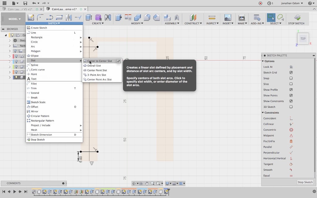
I go to Sketch > Slot > Center to Center Slot to draw the perimeter of the spacer.
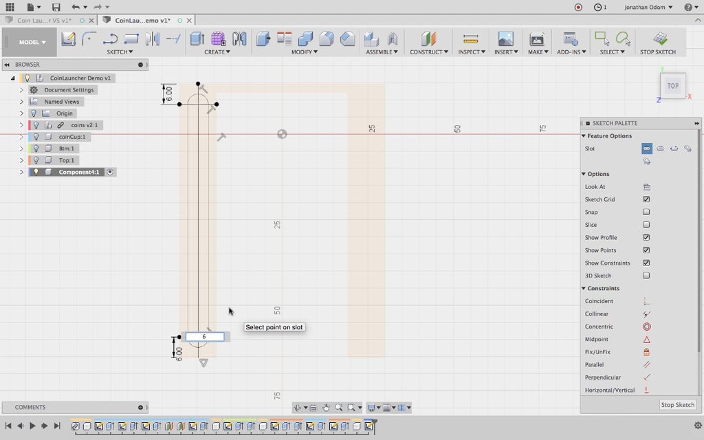
I click the intersections of the lines I just drew as the center points of the arcs at the ends of the slots, then enter 6mm as the diameter of the slot.
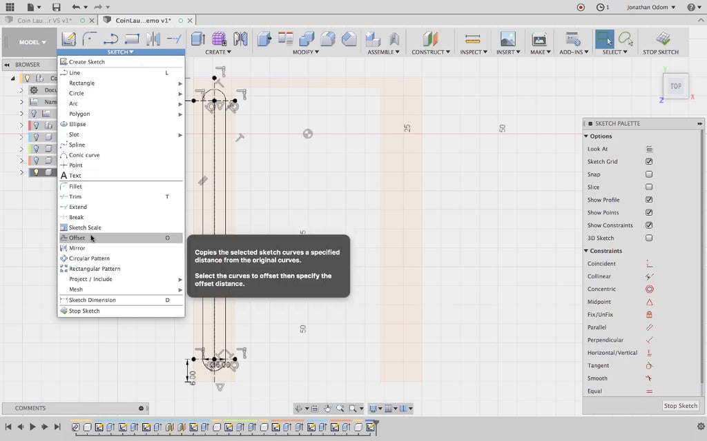
The spacer consists of a shoulder and a male part, so to draw the outline of the male part I go to Sketch > Offset.
I offset the slot by -1.5mm. This will give me a shoulder of 6mm and a male part of 3mm, which I know will work well with an FDM printer.
I want this spacers to be symmetrical, so I draw a centerline from midpoint to midpoint of the bottom part.
I use the Sketch > Mirror tool to mirror all the lines making up the slots on the left side of the sketch.
Once again, I change the parameters to make sure everything is updating properly.
I go to Create > Extrude to start the spacer bodies. I use the To Object Extent in the many and click on the lower corner of the bottom part. This extent ensure that the spacer will update if the thickness of the base changes.
Turning the sketch back on in the browser (remember, it hides automatically the first time it's used to make 3D geometry) I use all of the slot profiles to Extrude the shoulder to meet the underside of the top part. Join is the default Operation, and that's what I want in this case.
Finally, I extrude the inner slots to the top of the top part, completing the spacers.
As usual, I test the parameters to make sure everything is changing shape properly.
Step 7: Completing the Model
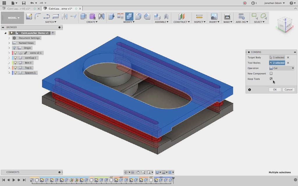
To make the parts friction - fit together, I use the Modify > Combine tool. The Target Body is the top part, and the Tool Bodies are the two spacers. I make sure Keep Tools is checked so that my spacers don't disappear when I complete the command. I repeat this step with the bottom part.
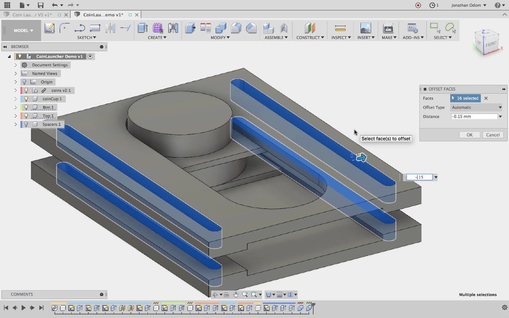
I use the Modify > Press/Pull tool to make the holes in the top and bottom parts slightly larger. This is necessary because the tolerances possible with a desktop FDM printer require a bit of wiggle room. An offset of -.15 is usually quite enough to get a good fit. On my Creality CR-10, I only need about .05mm to get a snug fit that can be removed and reset.
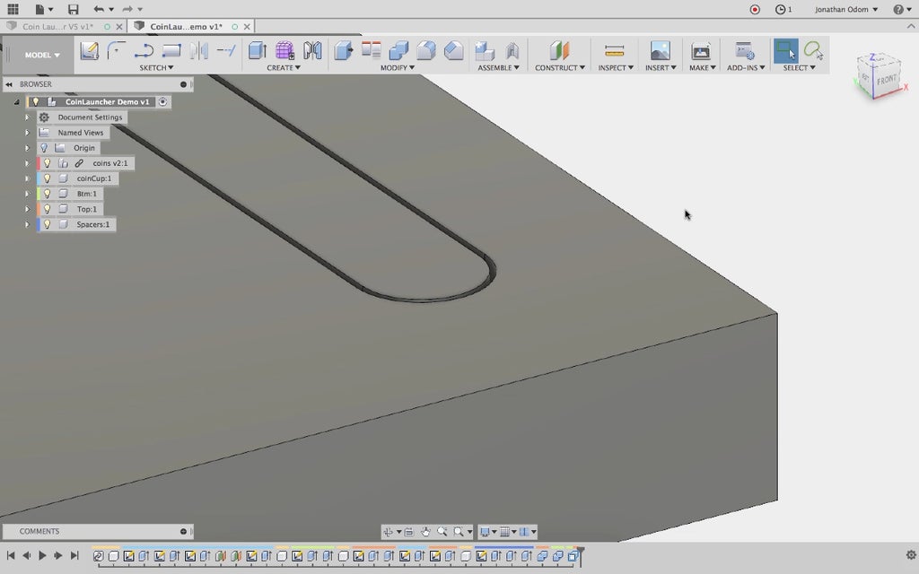
As you can see, there's a small gap between the male and female parts.
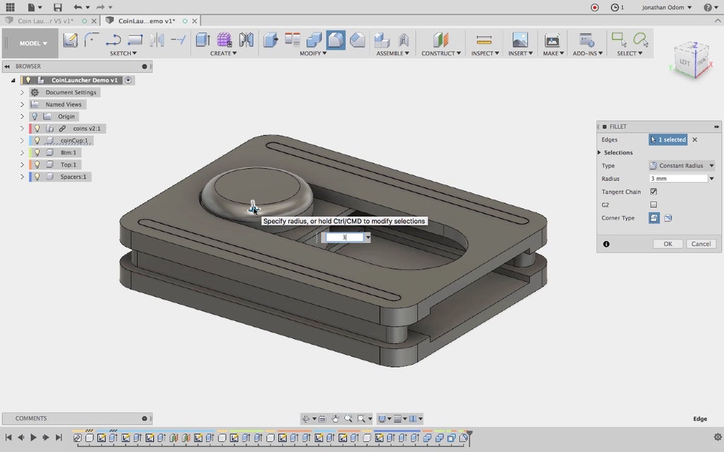
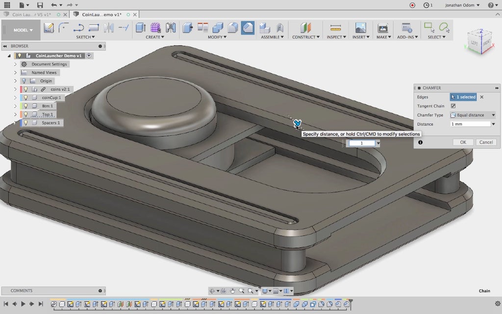
Any object that's going to need a lot of handling like this needs some finessing to make it a comfortable, pleasant experience. I use the Modify > Fillet tool to round out the edge of the coin cup knob.
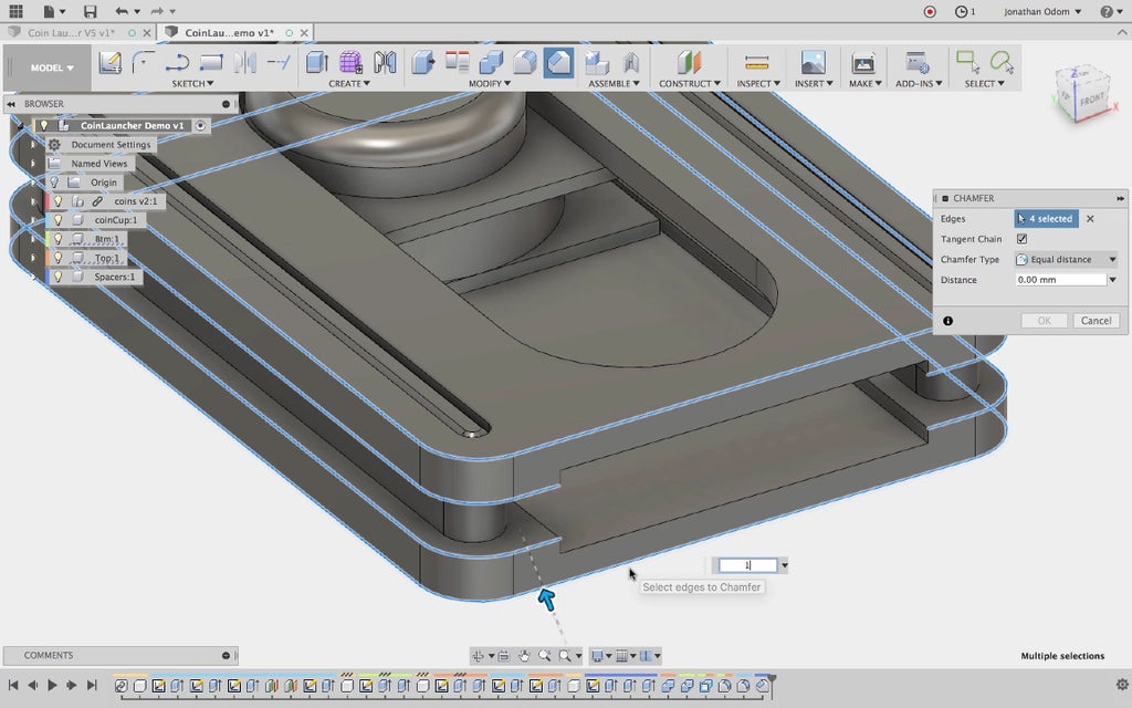
I use the Modify > Chamfer tool to to bevel the male edges of the spacers because this will make assembly much easier, and I do the same thing to the edges of the top and bottom parts. Sharp edges tend to be annoying with mild use of any object, and downright painful with heavy use.
I add another chamfer to the upper edge of the slot for good measure.
Once again, I test the parameters to make sure everything works.
Step 8: 3D Print

Here are the general settings I used:
Extruder Temp: 210ºC
Bed Temp: 60ºC
Infill Percentage: 30%
Support Pillar Resolution: 1mm
Support Infill Percentage: 50%
Layer Height: 0.2mm
My Simplify 3D profile for the Creality CR-10 is attached here as a ".fff" file.
The ".STL" files are printable parts designed for a 70mm rubber band.


Step 9: Assembly
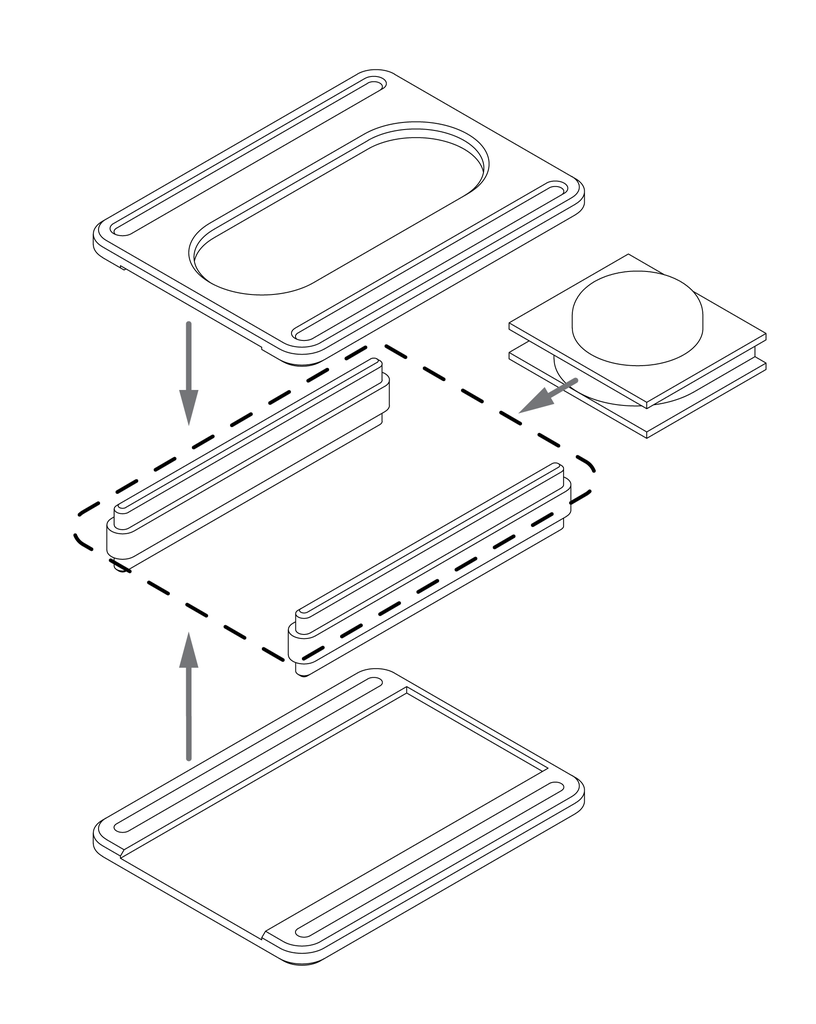
Assembly is easy:
- Insert the two spacers into the holes on the bottom part.
- Stretch the rubber band around the middle of the spacers.
- Push the coin cup back against the rubber band, then snap it in place against the ledge in the front.
- Hold the coin cup in place and press the top part onto the spacers.
If the fit is too tight to assemble or too loose to stay together, adjust the press/pull offset accordingly.
Step 10: Play the Game!
The game can be as simple or as complicated as you like.
The simplest version is that whichever coin is closest to the end of the table when all turns are done wins. You can shoot coins to bump your opponents' out of the way in the process.
You can also set targets divided at the end with tape, kind of like a game of darts.
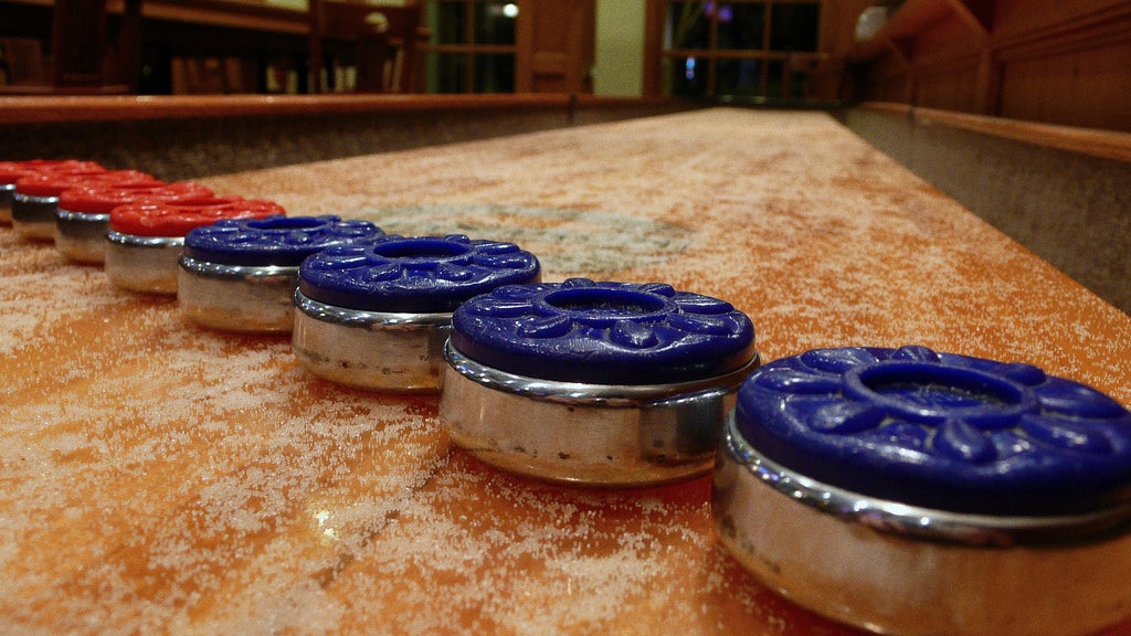

The typical tabletop shuffleboard setup has a polished surface dusted with slippery beads. The pucks glide smoothly across and require precise control.
This version isn't as fancy, but the whole game fits in your pocket and can be played on any table that's handy.
Give it a try and show use what you've made! Every IMadeIt posted is an automatic 1-year premium membership.


