

Introduction: 3D Printed Linear Motion (MVMT 92)


With this handy gadget, you can turn rotary motion into linear motion with ease! Using some skateboard bearings, machine screws, and 3D printed parts, the machine comes together in no time and can be used for all kinds of machines or robots.

507 Mechanical Movements is an encyclopedia of common mechanisms from the 1860's that serves as a good reference for this kind of thing. This mechanism is bases on number 92, "Ordinary Crank Motion".This is going to be along project, so if you've got a specific mechanism you'd like me to make, feel free to make a request in the comments!
I used mine to make a machine that endlessly draws a sine wave. Imaging trying to do this by hand- it's a good time to be alive!

Step 1: Tools + Materials
- Fusion 360
- 3D Printer
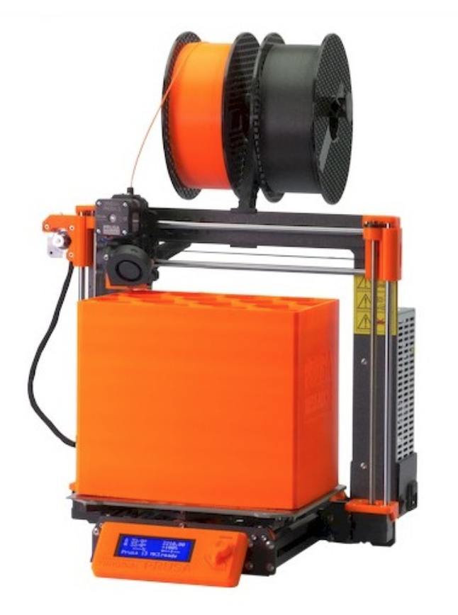
I use a Prusa I3Mk3S for just about everything. It's the best bang for your buck, in my opinion- very well made, 3D printable replacement parts, accurate and reliable.

- 3D Print Filament
- I used Matte Fiber HTPLA from Proto-pasta for this project, but pretty much any filament will work. I like this stuff because the finish looks really good.
- I used Polymaker Polyflex for the belt. It worked for a while but stretched out eventually, I'll probably redo this project with a big o-ring or a manufactured belt.
- 608ZZ Skateboard Bearings: There are lots of types to choose from, but any cheap ones will do. Don't worry too much about "spin time" as you would with fidget spinner.
- M3 Screws + Nuts: You could use any screws and nuts around this size, but I find these work well for small 3D printed mechanical projects.
- Receipt Paper: $4 on Amazon.
Fusion 360 is free and it's awesome. I use it for everything I design and fabricate.
Student / Educator License (renew free every 3 years)
Hobbyist / Startup (renew free yearly)
Step 2: Design / 3D Modeling
The video above is a step by step demonstration of the modeling process. The steps that follow describe what's in the video.
The f3d file in this step is the Fusion 360 archive that you can download and upload to a project in Fusion.

Step 3: Insert Bearing + Create Base

First, get a bearing into the canvas. Go to Insert>McMaster Carr Component, search "608 bearing", and navigate to the product detail of the first one you find. Make sure file type is set to 3D STEP and select Save. The bearing will come in as a new component which you can rotate 90º to make it vertical.
Next, Assemble>New Component to keep your design organized.
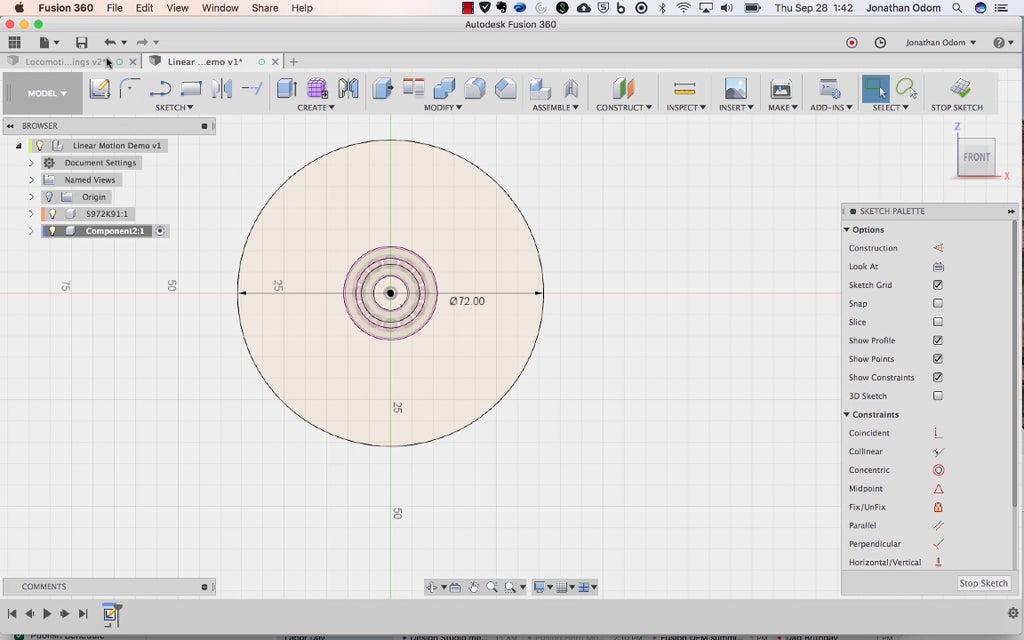
Create a sketch on the Front plane of the canvas and Sketch>Project/Include>Project to get the outline of the bearing into the sketch (be sure selection filter in that command is set to Bodies).
With the bearing perimeter projected, make a Sketch>Circle>Center Diameter Circle on the center of the canvas. Type in 72mm for the diameter.

Make a Sketch>Rectangle, then Sketch Palette>Constraints>Tangent to make three of the lines tangent to the circle as seen above.

Create>Extrude the profiles as shown above. If you made a new component before you started your sketch, leave the Operation as New Body, otherwise change the Operation to New Component.
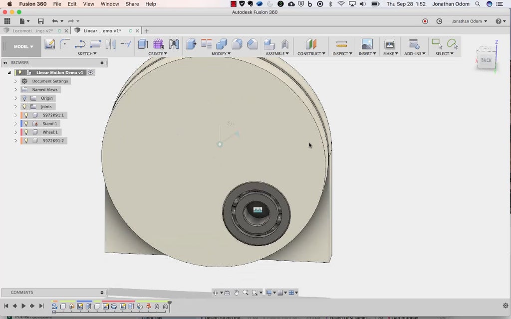
Step 4: Create a Wheel

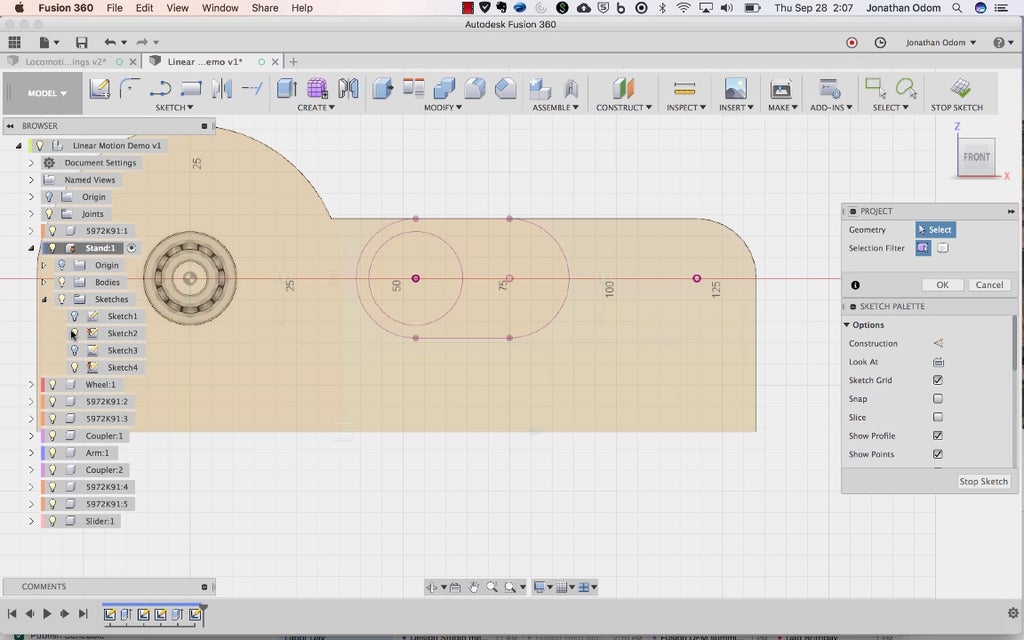
Activate the top level component (right-click>Activate) called Linear Motion Demo at the top of the browser in the screenshot above. Assemble>New Component to keep things organized, then create a new sketch on the Top plane of the canvas.
Sketch>Project/Include>intersect and click on the inner ring of the bearing.

Now you're going to draw a cross-section of a wheel that you'll use to revolve a 3D shape. Draw a center line by clicking on the model origin point and clicking somewhere to the left as shown above. Make sure the line is 90º.

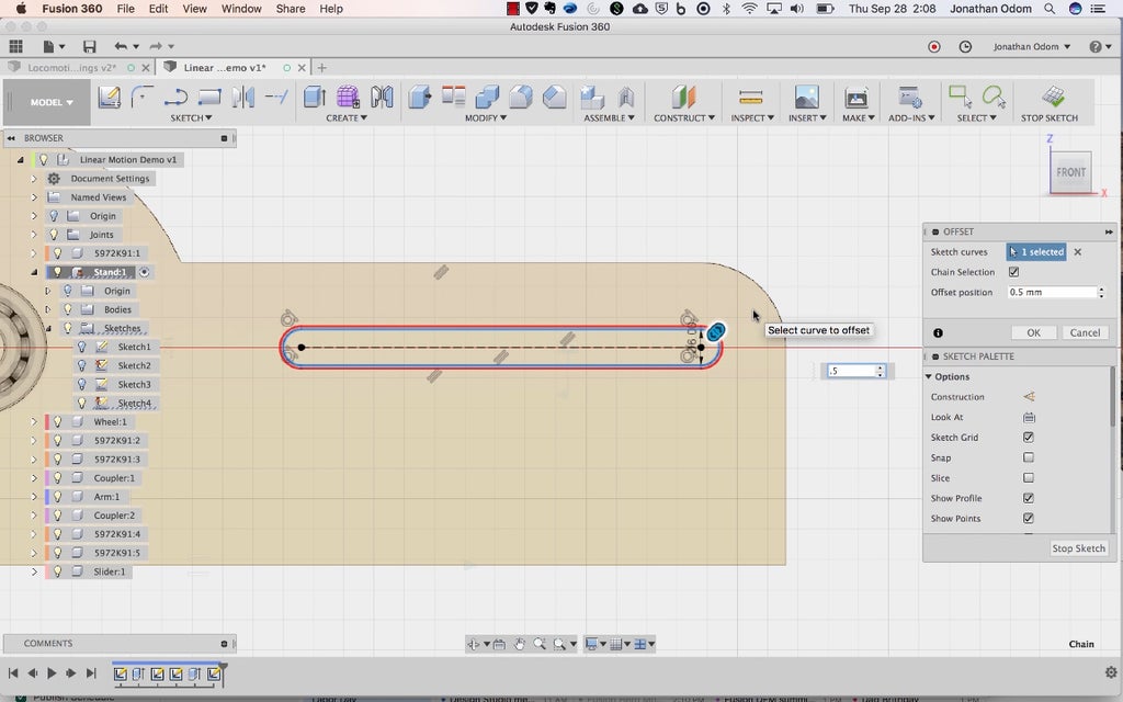
Sketch>Offset this line by 36mm (half of 72mm).

Draw a line that's perpendicular to the two other lines somewhere off to the left as shown.

Draw a cloud profile that looks something like what's shown above. There needs to be a shoulder against the bearing (shown above with a gap between them) and a kinked line to offset the face of the wheel.

Use Sketch>Sketch Dimension to get everything in place. The inside line is offset by .5mm to allow for some space between the press fit parts, the shoulder kink is set to 120º (this could be a right angle and it would still work, this just gives you a little more material for strength), the inside face of the wheel is 1.5mm from the face of the bearing, and the thickness of the wheel is 7mm (same as a bearing).
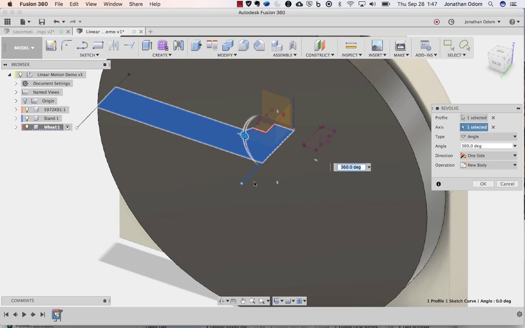
Create>Revolve with the profiles you just created, using the centerline as the axis of rotation. Make sure it's set to full rotation or 360º. If you're already active in your new component, New Body is fine for the Operation type.

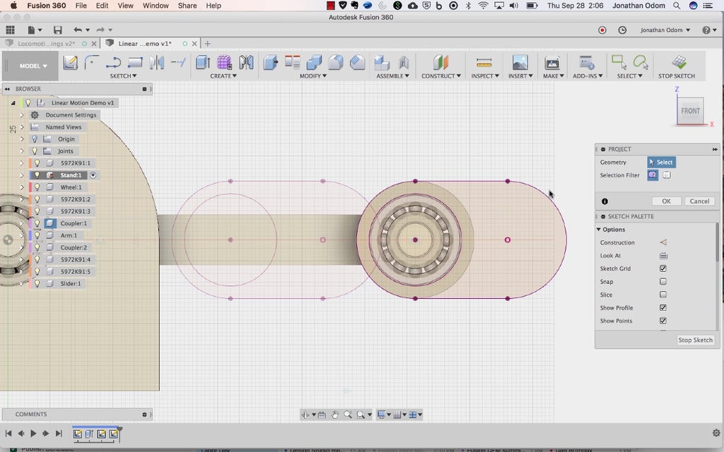
Create another sketch on the face of the wheel you just made. Draw a centerline from the center of the wheel off to the right somewhere.

Draw a 22mm circle (diameter of the bearing), then Sketch Palette>Constraints>Coincident constrain it to the centerline. Draw a perpendicular line to the centerline, then Sketch>Sketch Dimension it so that it's 3mm from the outer edge of the circle. Sketch Palette>Constraints>Tangent constrain the circle to the vertical line. This will make sure there's enough material on the outside of the wheel to keep from breaking with the bearing is pressed in.

Create>Extrude the circle through the wheel to make a hole for the bearing.

Copy/Paste the bearing component (with top level component active) then use the point-to-point move option to get the bearing exactly in the right spot.
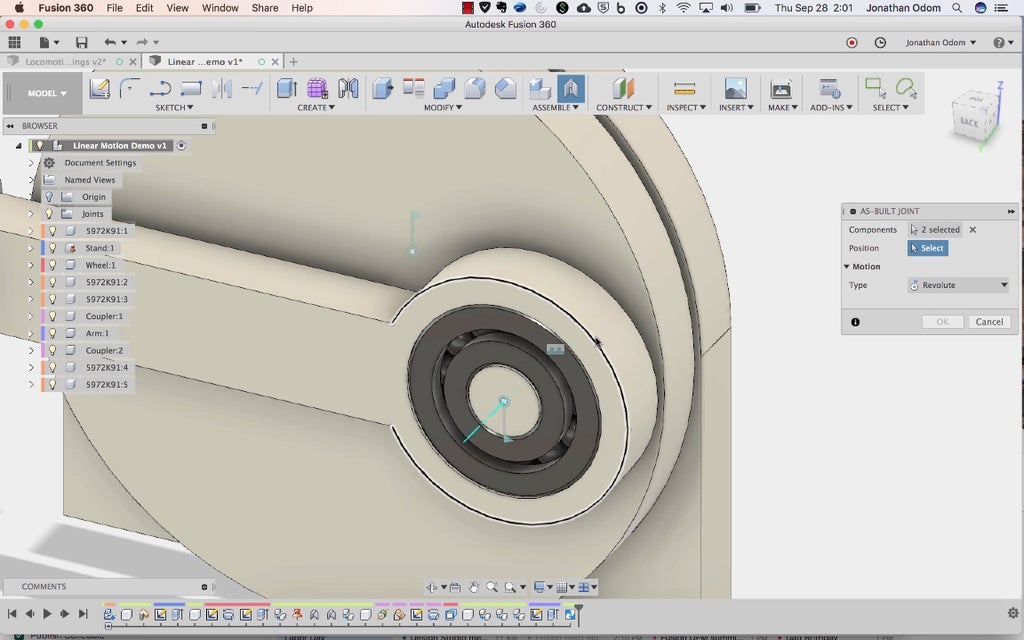
Step 5: Make a Revolute Joint

Now you're going to make the first joint. Before you do that, right-click on the base component in the browser and select Ground. This will keep the base from moving around when you move the joint.

Assemble>As-Built Joint and click on the wheel and the base. For Position, click on any circular edge on the wheel or the base as shown above.

This will make the wheel turn about the center axis. The bearing isn't moving because it's not joined yet.

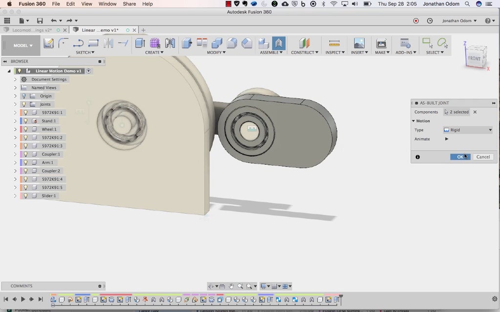
Do another As-Built Joint to connect the bearing to the wheel. This one should be Type: Rigid.
If you right-click on the first revolute joint and select "animate model" you should see the wheel turning with the bearing going along for the ride.
Step 6: Make a Coupler

Copy / Paste the bearing on the wheel and move it away from the face by 8mm, leaving a 1mm gap between them.

Assemble>New Component, then go to Construct>Axis Through Cylinder/Cone to make an axis. Click on the outer cylinder of the bearing and an axis line should appear.
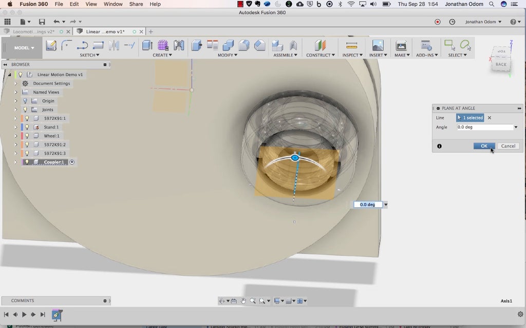
This axis is going to give you a plane to draw on. Construct>Plane at Angle and click on that axis and you should get a plane at an angle you can set. It doesn't really matter what the angle is.

Sketch>Create Sketch and click on the plane you just made. Sketch>Project/Include>Intersect and click on the inner rings of both of the bearings. Show/Hide the parts you don't need to see to sketch.

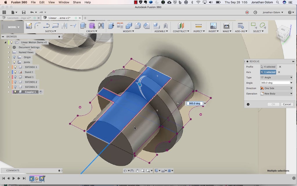
Draw a two Sketch>Rectangles as shown above- one between the bearings and one through their holes.

Use the Sketch Palette>Constraints>Coincident, then click each line of the new rectangles followed by a point that's in plane with them as shown above. When you've got them in place so that they go the whole extent of the bearing in both dimensions, Draw a centerline from the midpoints of the lines on the left and right. Create>Revolve, select the profiles that make up half of the cross section, then use the centerline or axis line for Axis.
Step 7: Make an Arm

Copy/Paste the new bearings and the coupler (with the top level component active in the browser) and move them over by 75mm.

Create a new component, then make a sketch on the face of one of the bearings on the outside. Sketch>Project/Include>Project and click on the outer rings of both bearings. Offset both of these outer edges by 3mm.
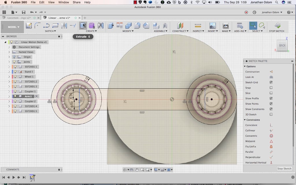
draw a rectangle that connects the two circles. I made mine 12mm wide by using the Sketch Dimension tool to make the lines 6mm from the center points of the circles on both sides.

Create>Extrude the profiles you need to make an arm with holes on each end. The arm should be 7mm deep (same as the bearings).

Assemble>Rigid Group and select the bearings and coupler that are together. This will make them stick together when you make mechanical joints.
Step 8: Make Revolute and Slider Joints
Assemble>As-Built Joint and select the arm and one of the bearings. Pick the center of one of the circles as the Position.

When you right-click on the center joint of the wheel and select Animate Model, you should see the arm turn with it.

Assemble>Rigid group the other set of bearings and the coupler on the other side as before.
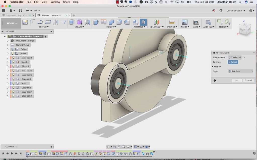
Assemble>As-Built Joint and select the arm and one of the bearings on this side. Pick the center of one of the circles as the Position.

Assemble>As-Built Joint and select the one of the bearings and the base component (called Stand in the screenshot above). Change the Type to Slider, then select the horizontal line and one of its end points on the Stand as the position.

Now when you right-click Animate Model on the first revolute joint, you should see this.
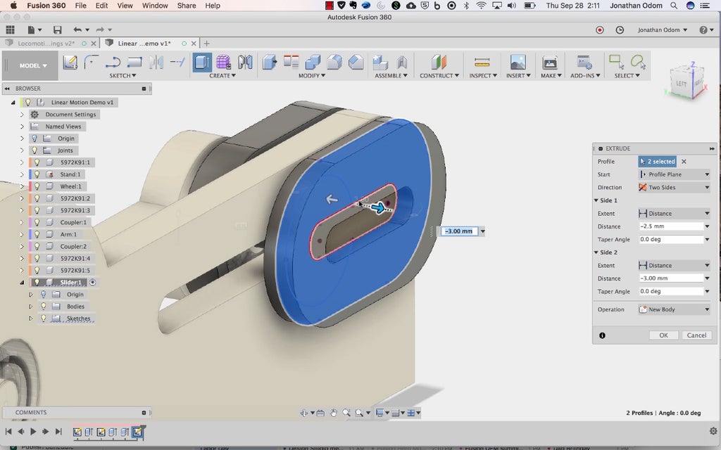
Step 9: Make the First Slider Part
Now you'll need to make a slider part. From the top level active component, create a new component.
Set the main revolute joint on the Stand so that it's 0º or whatever angle brings the arm to its innermost position as shown above.
Create a sketch on the face of the inner bearing, Project the outer ring of the bearing, then draw whatever shape you like for the base. I made a pill shape with a 3mm offset for the edge around the bearing, but a rectangle would work just fine. The important thing is that this component has a cutout for the bearing's outer ring.

Create>Extrude this profile so it's 7mm deep to match the bearing.
From the top level active component, create an Assemble>As-Built Joint>Rigid joint between the new slider component and the bearing.
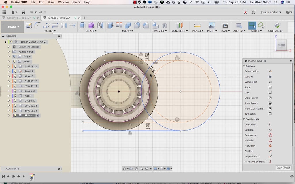
Step 10: Make a Slider Cavity on the Base

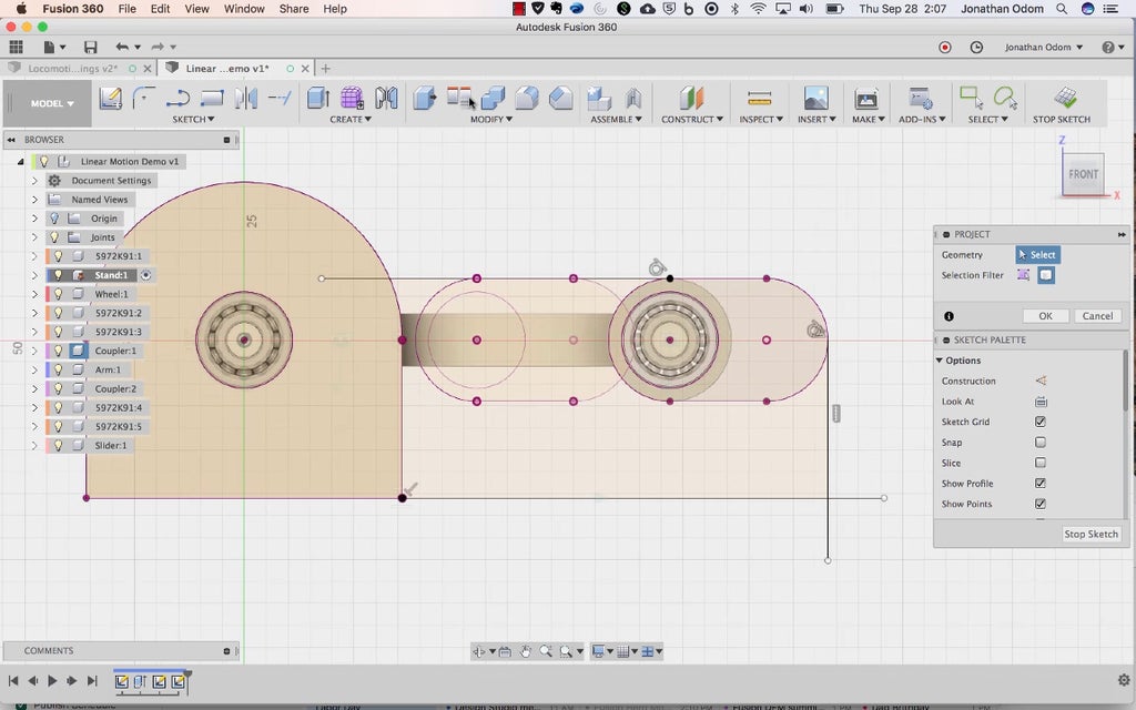
Right-click>Activate the Stand component in the Browser. Create a new sketch on the inside face of the stand, then Project the profile of the slider part you just made. Before you do this, make sure the arm is at its innermost position- if you drew the wheel the way I did, 0º should be the angle the wheel needs to be at. The important thing is that the arm is dead level and all the way to the left.
Stop that sketch, then set the wheel joint to 180º. This should move the arm so that it's in its outermost position. Make a new sketch on the face of the slider component. You'll be able to see the previous sketch as seen above.
Use the projected geometry to complete a profile for the slider part of the stand.

Create>Extrude the profile with Join selected as the operation to join the new shape to the Stand.
Create a new sketch on the stand, then project the geometry of that first sketch you made with the slider in the innermost position.

Using the center points as a reference, Sketch>Slot>Center to Center Slot, make a slot with a width of 6mm.
Offset the slot by .5mm. This will give you some freedom of movement and reduce friction.

Extrude these profiles (the slot and the offset) through the Stand so that it cuts all the way through.
Step 11: Make a Cap for the Slider

Now you'll need to make a post feature for the slider part. Activate the Slider component, then create a Sketch on the outside face of the Stand. Project the circular end of the slider part.

Use the center points of the circular edges to make another Slot that's 6mm wide, then Extrude that slot shape so that it touches the back face of the slider. You can set Extent to To Object and click on the face of the slider and it should go the right distance. The Join operation is what you want here.
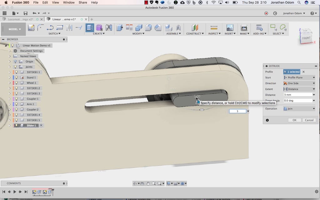
Extrude the face of the slot shape out by 3mm.

Create a new sketch on the extruded face of the slot feature, then Project the body of the slider.
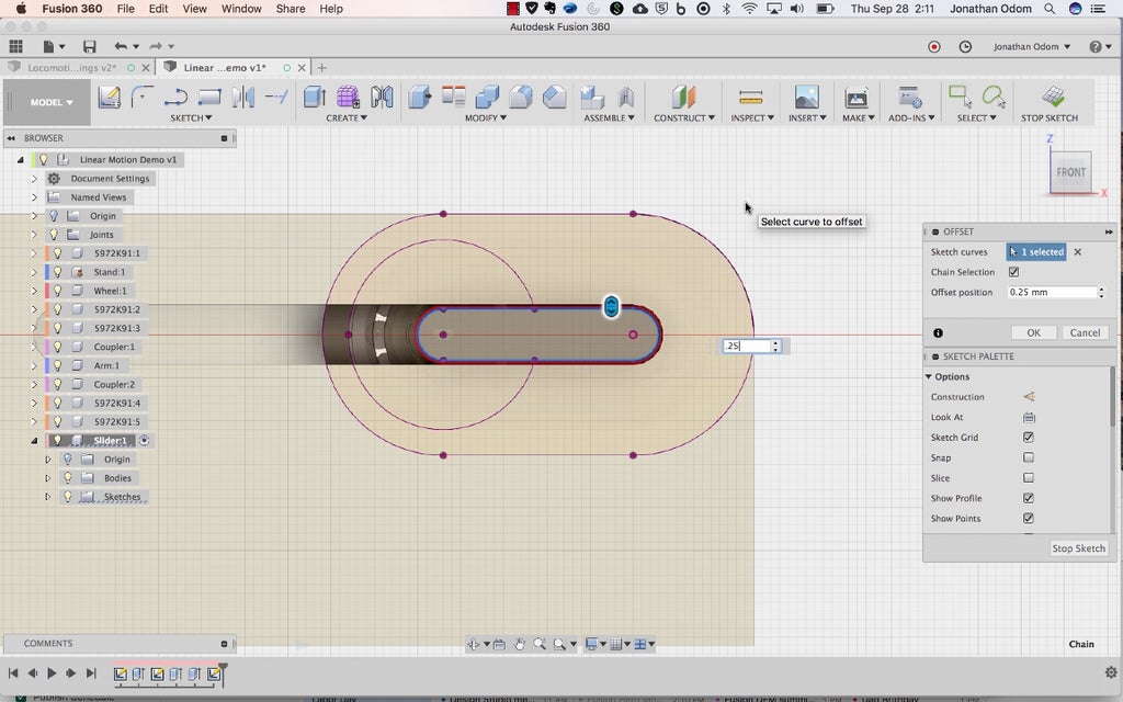
Offset the slot by .25mm. This will give you a decent tolerance for press-fitting.
Use this profile to Extrude a new part symmetrically by 3mm (6mm total).
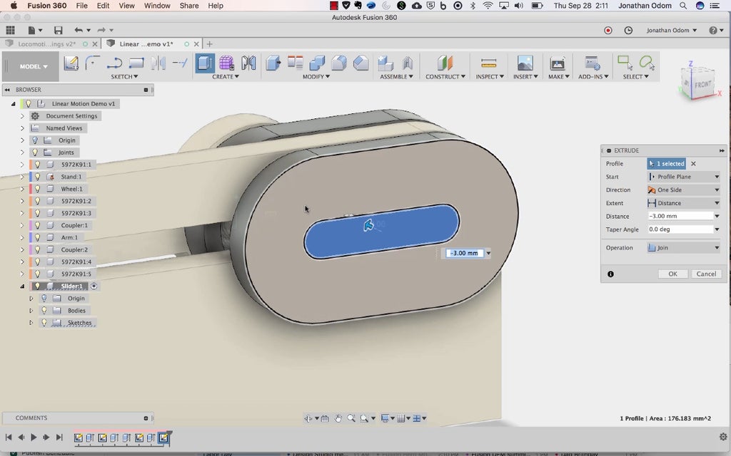
Create a sketch on the front of this new part, then use the inner pill shape to Extrude it in until it touches the end of the post. In other words, close the hole.
Step 12: Make a Driver Socket


You're almost done! Now all you need is a driver socket to make the wheel turn. Create a new component, Create a sketch on the Top plane of the canvas, then Intersect the inner part of the first bearing. Draw a shape like the now shown above with a centerline along the model axis. The important thing is that there's a shoulder the bears against the inner rings of the bearing and that it's about 10-15mm deep.

Create>Revolve with the axis selected to make the part.

You can use any method you want to drive the motion (dc motor, hand crank, etc.), but I made mine so that you can test it with a hand drill.
Create a sketch on the face of the socket, then Sketch>Polygon>Circumscribed Polygon and select the center of the axes as the origin point.
The width of a standard 1/4" socket driver is 6.8mm, so since this tool wants a radius for the dimension, just type "6.8mm/2" and you'll get a polygon the right size. 6 sides is the default, and that's what you want.

Extrude this profile into the socket to make the hole.

That's it! The picture above was made using Inspect>Section Analysis so you can see how all the parts interact.
In this tutorial I didn't get into the nuances of making all the nice little features and screw attachments from the example I made, but ask my anything in the comments and I'll do my best to get back to you quickly.
Step 13: 3D Printing: Rotary > Reciprocal Mechanism


Attachments


Step 14: 3D Printing: Sine Wave Drawing Machine
The sine wave drawing machine (STL files in this step) is an example of how this mechanism can be used. It uses a roll of receipt paper (in the Tools + Materials step above) on a spool holder. There's a belt printed with Polyflex, but I printed everything else with ProtoPasta Matte Fiber PLA.
Here's how I figured out the length of the belt:

I measured the radii of the pulleys, then got the circumference of each pulley, then found the arc length that would be engaging with each pulley. The driver pulley and the roller pulley both have 1/2 engagement with the belt, and the pulleys that turn the belt to make a right angle both engage by 1/4.
If you download the Fusion archive in Step 3 above, you'll see the full assembly.
Attachments


Step 15: Assembly: Rotary > Reciprocal Mechanism


The assembly is pretty straightforward despite what it might look like from the pile of parts. The bearings press-fit into the holes in the 3D printed parts, the nuts press-fit into the cavities in the parts, and the screws hold the parts together.
If the fit is too snug on the bearings (this will depend on the kind of filament you used and the precision of your printer), you may need a C-clamp to press them into place.

I made a plywood base to attach the machine to as well.
Step 16: Assembly: Sine Wave Drawing Machine


CORRECTION:
- "#4 socket" in the drawing above is actually two parts: "couplerUp" and "couplerDn" in the STL files attached previously.
The slider has a socket built in that anything can be attached to. In this case, I've attached an arm that holds a pen. on the right, there's a platform (14), a pair of rollers (5, 6), a set of pulleys (3), and a spool holder (9) that work together to create the drawing motion. The pen reciprocates back and forth on the slider, and the pulleys work with a belt to make the rollers turn continuously, feeding the paper through. This makes a sine wave!

Step 17: Draw Forever


Linear motion can be used for an endless number of mechanisms. What will you use yours for?


