

Introduction: 3D Printed Powerful Laser Pointer


Hi All! Today I offer You to make a powerful laser pointer that burns things!
Body of this laser pointer is made primarily of plastic. However, the heat sink is still metal, but metal work is minimized. Heat from laser diode is out into a plate on side of the laser pointer, and heat is go directly into user’s fingers, which also allows control of the laser diode operating temperature.
I was inspired to create this project by the LaserKids.
I express my gratitude to Yun Sothory for this site and his personal assistance.
Supplies


Tools:
- 3D Printer and its consumables.
- Glue for Your 3D plastic.
- Soldering tools.
- Multimeter.
- 30mm ring drill.
- M3 screw tap.
Materials:
- Laser diode NUBM08 or NUGM04 or other similar lensed laser diode.
- Round female pin header connector.
- LED Driver For Cree 10W T6 XML.
- Switch KCD11.
- 2x Li-Ion rechargeable battery 18350.
- 2x Сonical spring from old computer graphics card.
- Some wires 0.08mm or above. I use silicone insulated wires.
- PVC binding cover.
- Сopper tape.
- Thermal compound.
- 3mm aluminum plate.
- 1mm aluminum plate.
- 5x M3x20mm flat head bolt.
- 2x M3x6mm flat head bolt.
- Nail 1.5-2mm dia.
Step 1: Make Main Body Part


Print main body.
Stick a strip of copper tape by perimeter of threaded part of the body.
Take three strips of copper tape about 10cm. Stick them along inside of the body, as shown in the photo.
Attachments

Step 2: Solder Negative Conductor


Solder ends of the copper strips.
Take two pieces of blue wire about 4cm. This will be negative conductor.
Solder the wires to end the copper strips.
Step 3: Make Dielectric Wrap


Cut a piece of size 120x70cm from PVC binding cover.
Roll this piece into a tube and insert it completely into the body from the thread side.
Step 4: Prepare Dividing Walls


Print two dividing walls and insert nuts into them as shown in the photo.


Step 5: Make Flexible Contact for the Battery


Take spring and two pieces of red wire about 4cm. This will be positive conductor.
Solder the wires to the spring at edges.
Insert the wires into holes of the lower dividing wall so that spring fits into ring notch.
Heat the spring with a soldering iron so that base of the spring is firmly fused into the plastic.
Step 6: Glue the Dividing Walls

Glue the dividing walls into the main body by using glue for Your 3D plastic.
Step 7: Make Battery Lid


Print the battery lid and connector.
Place several strips of copper tape on concave side of the lid connector, so that the tape reaches the edges.
Solder wide part of the spring to the copper tape in the center of the lid connector.
Insert the connector into the lid .


Step 8: Make Battery Connector


If You are using a batteries with a raised positive terminal, You can skip this step.
Print battery connector. Wrap middle part of the battery connector with copper tape.
Solder the copper tape on both sides to create small bulges.
Attachments

Step 9: Make Cover With Switch
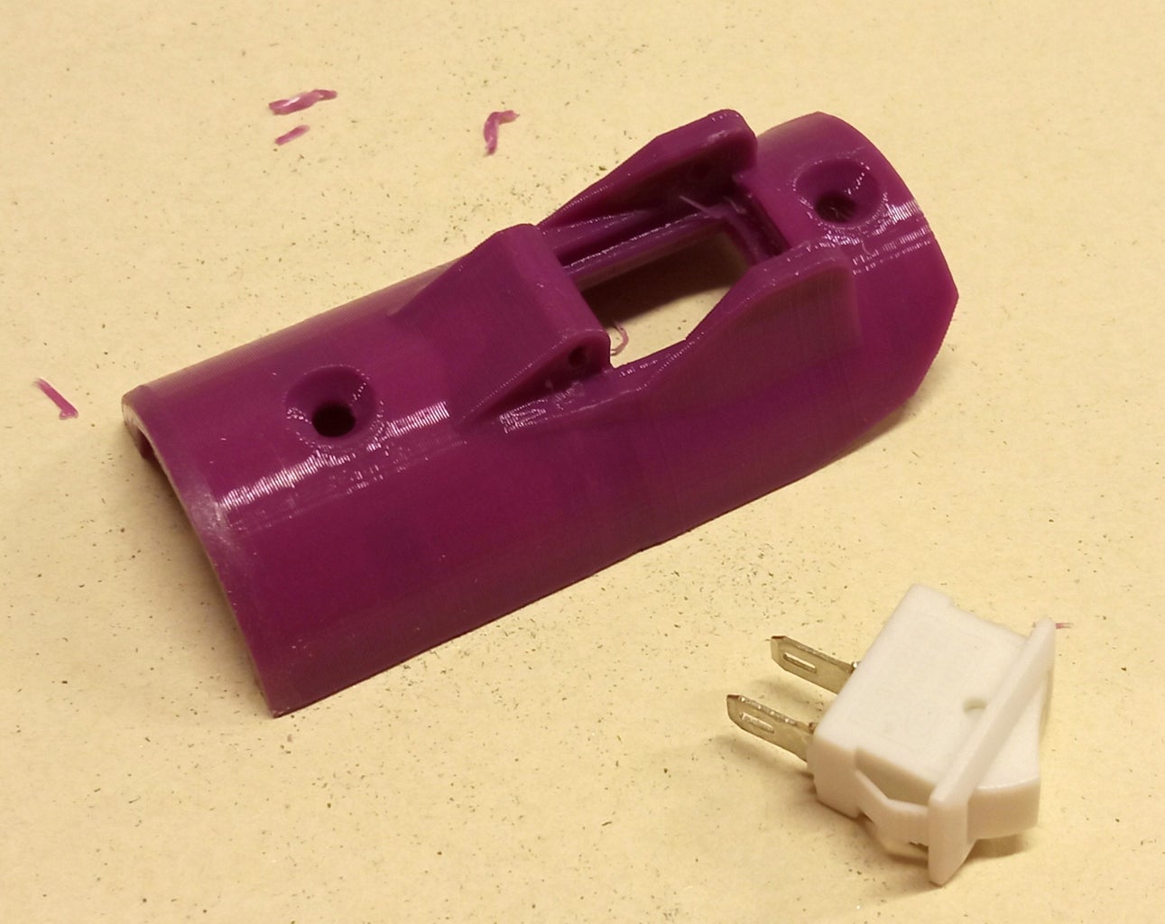
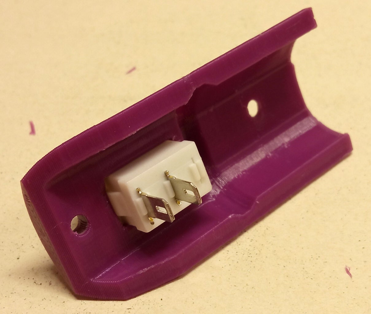

Print the cover with with hole for switch. Insert switch into this hole.
Attachments

Step 10: Make Switch Cover


Print a cover for the switch.
Take a nail and cut it to 16mm in length. Drill a hole in the plastic hinge joint to diameter of Your nail or 0.1 mm less, so that the cutted nail fits tightly into this hole. Connect both plastic parts and press the axle made from a nail into the drilled hole.
Attachments

Step 11: Adjustment of the Driver


This device utilize driver designed to power LED. However, experience has shown that these drivers is excellent for powering laser diodes.
Now You need to adjust the driver to work with Your laser diode. To do this, You need to change the driver output current. And to do this, You need to change the resistance of the driver adjustment resistors (see photo).
Warning. Before starting the adjustment, carefully read the datasheet for Your laser diode. Determine the maximum allowable supply current and try not to exceed it when adjusting.
By default, this driver has two 0.18 Ohm resistors connected in parallel, total 0.09 Ohm. This resistance corresponds to an output current 2.2 A.
To get an output current of 3.2 A (for NUBM08) You will need to make the adjustment resistance 0.06 Ohm. This resistance can be obtained by adding 5 pcs 1 Ohm resistors in parallel.
To get an output current of 2.0 A (for NUGM04) You will need to make the adjustment resistance 0.1 Ohm. This resistance can be obtained by removing one 0.18 Ohm resistor and adding 4 pcs 1 Ohm resistors in parallel.
If You need to set other output current, You will need to select the adjusting resistance Yourself.
*As a test load for this driver I use a powerful 1 Ohm resistor at 5W.
Step 12: Make Round Heatsink Plate


Using a 30 mm ring bit, drill out 4x disks from 3 mm aluminum. File this disks to even shape by entire thickness.
Make a 7 mm hole in the center of the 3x disks. One disk should be without hole.
Step 13: Drill the Circles

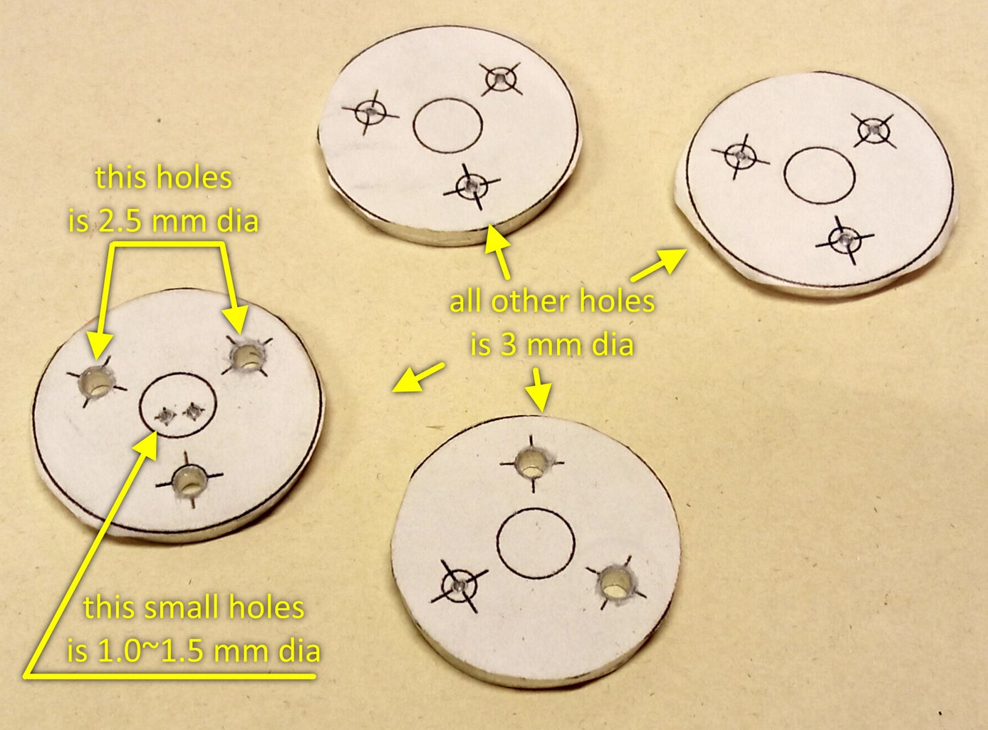


Print laYout of heatsink parts using ordinary 2D printer.
Glue the round layouts onto the aluminum disks. The template with two small holes is destined for a disk without a big hole. At indicated points drill holes of diameter that specify in the layout. The two small holes should be 1.0~1.5mm in diameter. Pins of the laser diode will pass through these holes along with the insulation.
In the disk with 2.5 mm holes, make an M3 thread using a tap. Sand one side of this disc with fine sandpaper on flat. The base of the laser diode will be pressed to this side of the disk.


Step 14: Make Spacer Washers


Using the previously printed layout, make 3 pcs spacer washers from an aluminum plate 1.0~1.2 mm. Sand the flat surfaces of these washers using fine sandpaper on flat.
Step 15: Make Heatsink Plate


Glue the layout of rectangular part onto a 3mm aluminum corner. Cut this part using a hacksaw.
Drill 2.5 mm holes in the specified points. Cut M3 threads in these holes using a tap.
Step 16: Laser Module Assembly


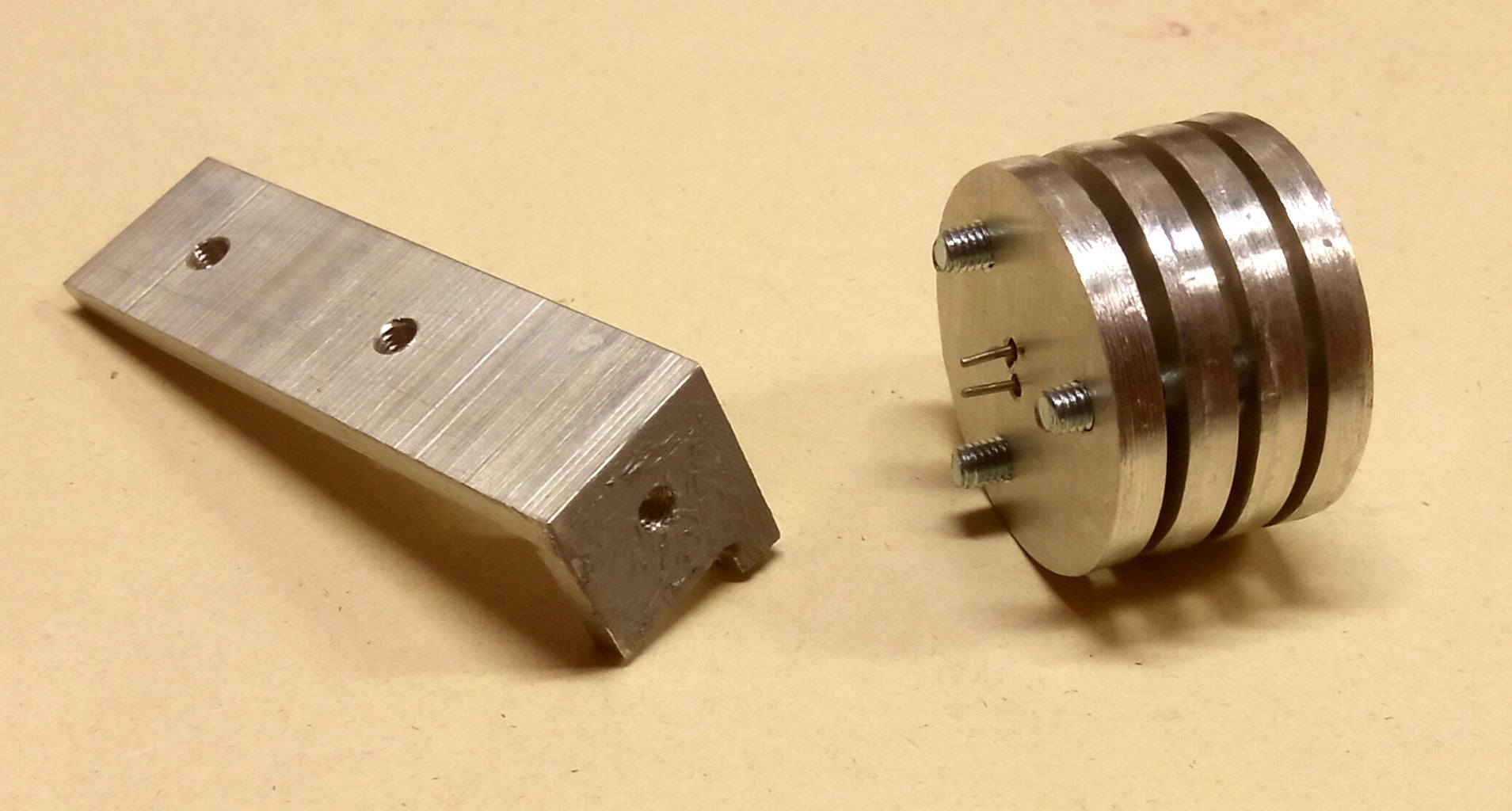


Place pieces of insulation from the wire over the diode pins so that they fit into the small holes in the heat sink disk.
Apply a thin layer of thermal compound to the heat sink disk where the base of the laser diode will be placed. Also apply thermal compound to heel of the rectangular aluminum part.
Attach the laser diode to a disk with small holes using thermal compound so that the diode pins with insulation fit into these small holes. Assemble a stack of disks with a large hole, interspersing them with spacer washers and insert M3 screws. Make sure the large holes in the disc stack are aligned. Join the disk with diode and the stack of disks so that the diode goes inside the stack. Screw the screws into the disk with diode, but do not tighten it. The screw that does not have a conform thread in the disks stack screw into the heel of the rectangular piece. Align the rectangular piece with the stack of disks; to do this, You can temporarily attach the laser module to the plastic body of the laser pointer. Closely wipe off excess thermal compound.
Carefully checking the laser diode datasheet, mark the positive and negative pins of the diode on the stack of disks rear.
Step 17: Power System Assembly


Take the laser pointer body and connect the power wires to the pointer driver:
- Solder the blue wires to the outer circular contact pad on the bottom of the driver.
- Red wires, through the switch in the cover, solder to the central contact pad on the bottom of the driver.
Solder a three-pin connector to the driver output so that when connecting it to the laser module, the polarity exactly matches that indicated on the module.
Connect the powerful 1 Ohm resistor to the driver output. Insert the batteries into the pointer body with the plus side facing to forward. Check with a multimeter that the driver is working and producing specified current.
Step 18: Laser Module Installation


Connect the driver output to the laser diode.
!!! Make sure that the polarity of the driver connection to the diode is correct !!!
Attach the laser module to the plastic body using short M3 screws from inside. Attach the cover with switch to the body using long screws.
Step 19: Let's Burn!!!


Insert the batteries and try to turn on Your new shiny laser pointer.
Step 20: Make Face Lid


Print a lid. If the lid does not fit Your laser pointer, this may be due to inexactness making of metal parts. Adjust design of lid in Your favorite 3D editor to suit Your laser pointer.
Cut a 20 mm dia circle from aluminum tape. Stick this circle inside the lid. This will save the lid from burnout if the laser pointer is accidentally turned on.
Now You can carry Your laser pointer in pocket without fear of clogging the laser diode. And a special cover on the switch will prevent unauthorized switching on, for Your own safety.


![Tim's Mechanical Spider Leg [LU9685-20CU]](https://content.instructables.com/FFB/5R4I/LVKZ6G6R/FFB5R4ILVKZ6G6R.png?auto=webp&crop=1.2%3A1&frame=1&width=306)


