

Introduction: 3D Printed Screw-propelled Robot With Video Feed


A screw-propelled vehicle is a type of land or amphibious vehicle that uses one or more auger-like cylinders fitted with a helical flange to move. The cylinders are rotated by an engine, and the flange engages with the ground or water to propel the vehicle forward. Screw-propelled vehicles are often used in areas with difficult terrain, such as snow, ice, mud, and swamps. They are also used in some military applications.
So in this instructables we are going to make a fully 3d printed simple version of a screw-propelled vehicle, i tried my best to make it as simple as possible build, so anyone with a 3d printed can build it, i also tried to reduce the number of parts in it like ball bearing which is totally unnecessary for this small light robot. it is based on Seeed Studio XIAO ESP32S3 Sense, we can control this robot with a smartphone through wifi, also we can also get a low-latency video feed from the robot so let's get into it
Supplies

Parts
- 2*N20 motor 3v 50 rpm
- 25mm 5v fan
- TP4056 BMS
- 2*Red LED
- Heat sink for camera
- Heat sink for Xiao
- DRV8833 motor controller
- Slide ON-OFF switch
- Seeed Studio XIAO ESP32S3 Sense
- 2*18650 battery ( I am using a battery from an old laptop )
- 12*CSK Allen M3 x 10mm
- 2*Socket Botton Head Cap Screw M3 x 20 mm
- heat sink compound
- connecting wires kit
- Kapton tape
Tools
- Allen key
- Sandpaper
- 3d printer
- Soldering kit
- Glue gun
Step 1: History of Screw Propelled Vehicles

The concept of a screw-propelled vehicle (SPV) was first proposed by Leonardo da Vinci in the early 1500s. However, it was not until the 19th century that the first practical SPVs were built. These early SPVs were used for a variety of purposes, including agriculture, transportation, and military applications. In 1868, Jacob Morath, a Swiss immigrant to the United States, patented a twin-screw plowing machine. This machine was one of the first examples of a practical SPV. In 1899, the Peavey brothers of Maine built one of the first screw-propelled vehicles that was actually used for transportation. Their vehicle was used to transport goods between their farm and a nearby railroad station. In the early 1900s, SPVs began to be used for military applications. The British Army used SPVs to transport troops and supplies during the Boer War. The German Army used SPVs to transport troops and supplies during World War I. Today, SPVs are used for a variety of specialized applications, such as search and rescue, oil and gas exploration, and military applications.
(Source Wikipedia)
Step 2: Modeling in Autodesk Fusion 360

I used Fusion 360 for planning and designing this robot, but I am not fully getting into how I modeled it, but we will look at how I designed the screw wheels of this robot, and we will discuss it in the next step, you can skip this step if you need. all design files are given below


Step 3: Modeling the Screw Wheels

let's start with creating a cylinder
- make a coil from the top side of the cylinder we are going to choose a diameter of 20mm, and I choose these parameters
- Revolution: 2
- Height : -120mm
- Section: Triangular
- Section size: 9mm
- Operation: Join
you can play with this parameter as you like
- Rotate the cylinder to 180° and again create a coil in it and use the same parameter that was used previously
- Now we need to make the cylinder sides pointy for that I created a sketch and used the Revolve tool with cut operation
yep, we made it.
Step 4: 3D Printing

I used my Anet a8 for 3d printing these parts, it is like 6 years old, sorry for the print quality, I will update to Anyubic Karbo 2 Neo soon !!. 3d printing screw wheels were hard because of the difficulty of removing the supports, I just attached all the.STL files and.STEP files in step 2
Step 5: Uploading Code to XIAO

I always like to upload the code to the microcontroller before assembly. Here we are using a tiny Xiao esp32s3 sense from the Seeedstudio. It is a highly integrated, Xtensa processor ESP32-S3R8 SoC, which supports 2.4GHz WiFi and low-power Bluetooth BLE 5.0, As the advanced version of Seeed Studio XIAO ESP32S3, this board comes with a plug-in OV2640 camera sensor for displaying full 1600*1200 resolution.
I am using Arduino IDE for flashing the code follow these tutorials for setting up IDE for XIAO ESP32S3 and learn more about this board
https://www.youtube.com/watch?v=qNzlytUdB_Q&t=944s
and thanks techiesms for the code and inspiration for this project
Step 6: Testing the Xiao

After flashing the Xiao will start a wifi hotspot
SSID : ROBO
Password: PASSPASS
const char* ssid = "ROBO";   //Enter SSID WIFI Name
const char* password = "PASSPASS";   //Enter WIFI Password
you can change this if you need from Code.ino
After Xiao has created a hotspot successfully it will show an IP address in the serial monitor
AP IP address: http://192.168.4.1
Starting web server on port: '80'Starting stream server on port: '81'
after connecting wifi with your smartphone open your browser and enter this 192.168.4.1 IP address, wait for the connection establishment. if everything works you can see your face in it 😅
Step 7: Wiring Diagram

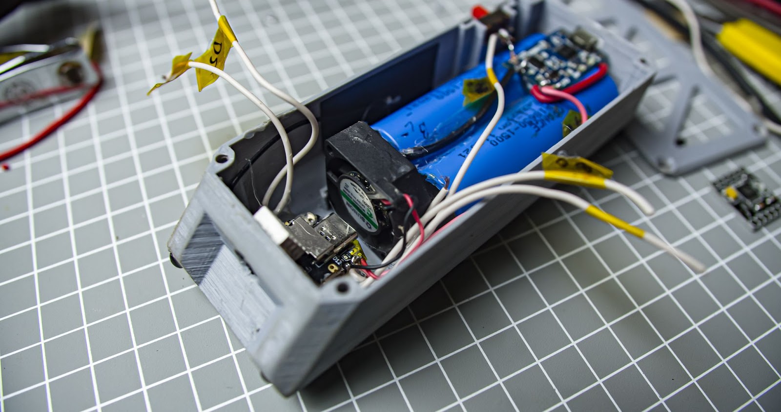
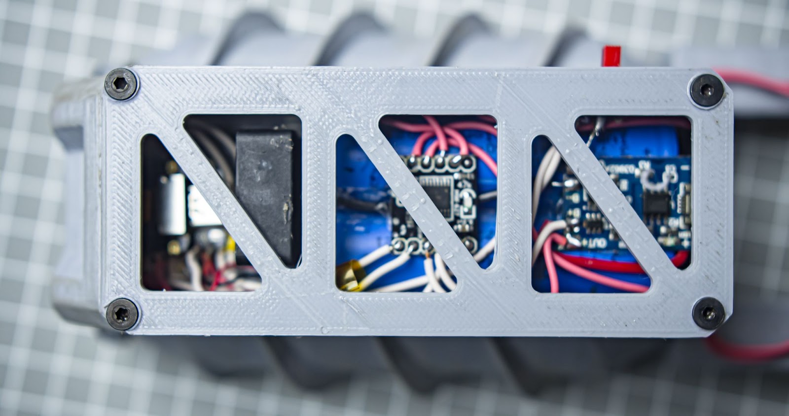
The brain of this robot is Xiao, there are signal 4 wires from the Xiao going to the DRV8833 motor controller, and the main power source is two 3.7v 18650 batteries connected in parallel, we are using a TP4056 Battery Charging Module for recharging the batteries. we have a small 5v fan for cooling the xiao, We have two N20 3v 50rpm motors which are controlled by the DRV8833, We also have two LEDs for the illumination, all of which can be switched on with an ON/OFF slide switch
Step 8: Assembly and Wiring

I tried my best to make the assembly simple, most of the components are fixed with a hot glue
now we can start with LEDs
Step 1
After cutting the terminals of the LED, I connected two LEDs in parallel,
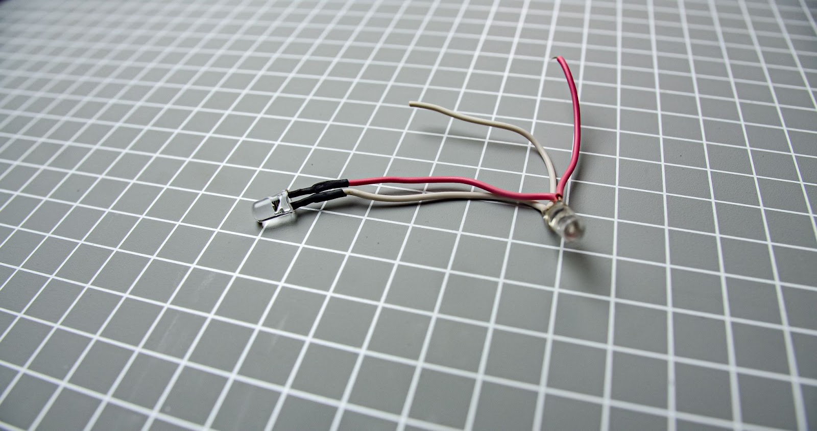
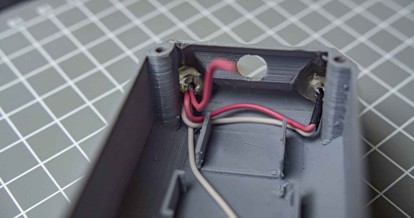
Step 2
attach the LED to the main body with a glue gun
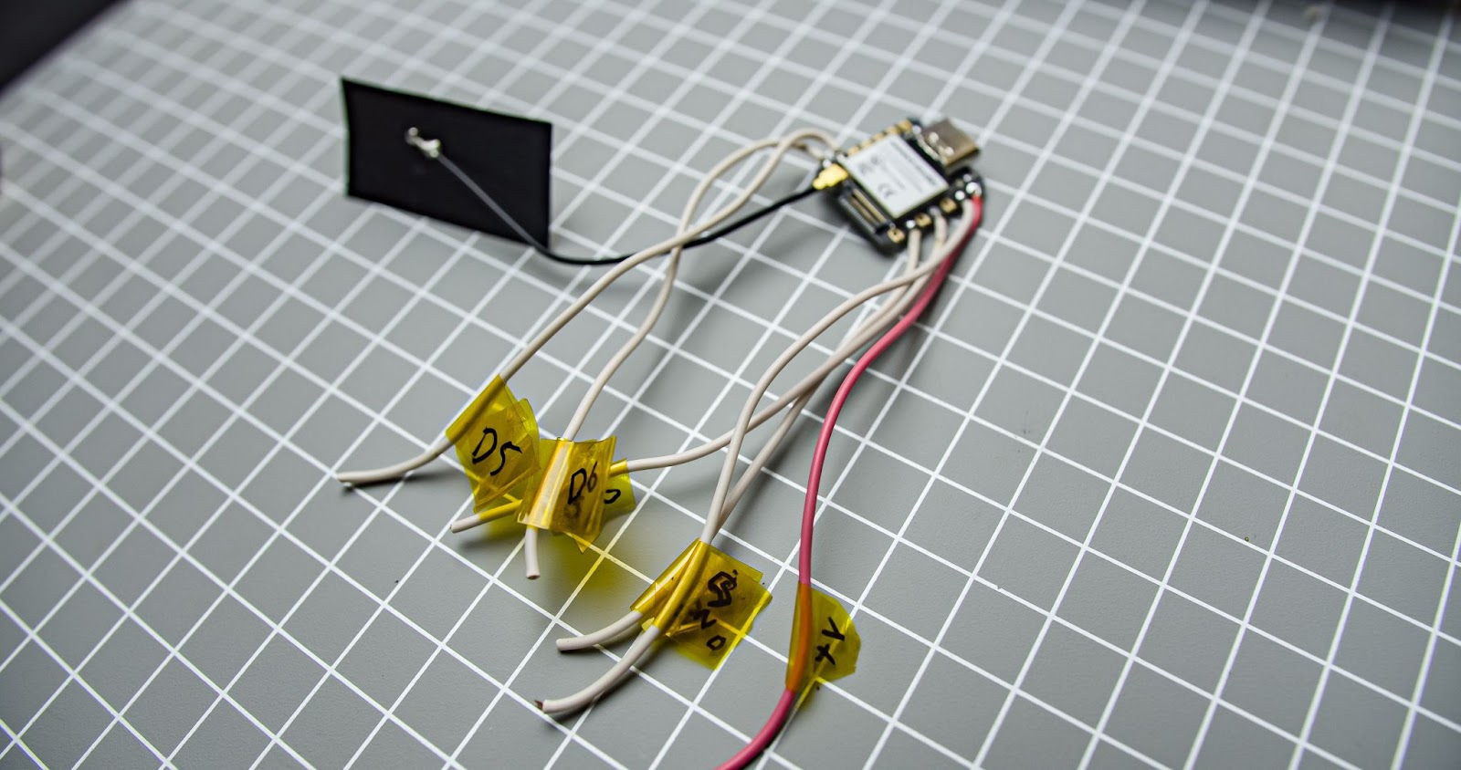
Step 3
solder all GPIO pins with a long wire also tag all the wires with corresponding GPIO numbers
Step 4
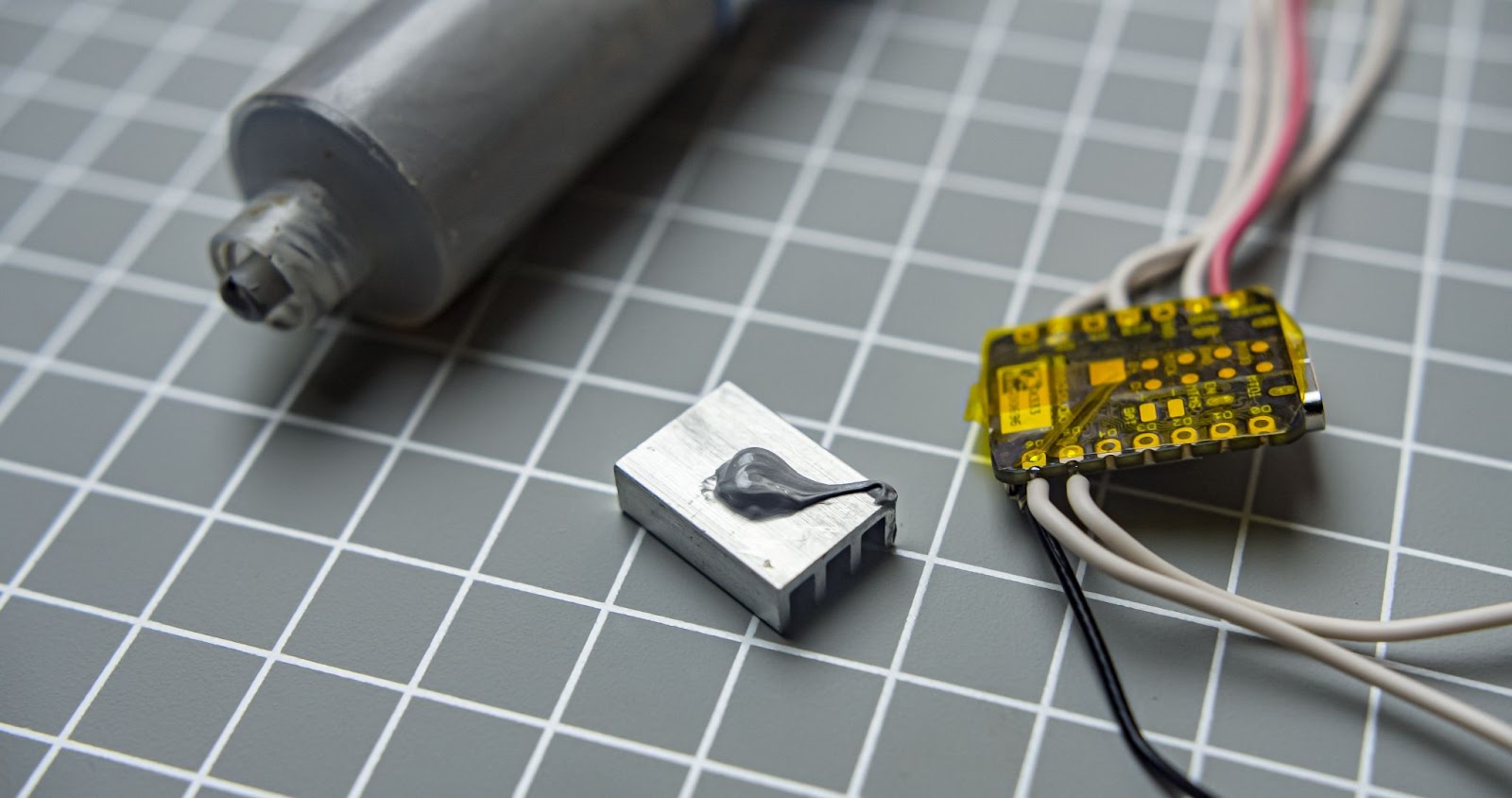
covered all exposed copper pads under the xiao with Kapton tape, I am including a heat sink behind it for dissipating heat from the xiao, Kapton tape will help to prevent copper pads from touching the aluminum heat-sink 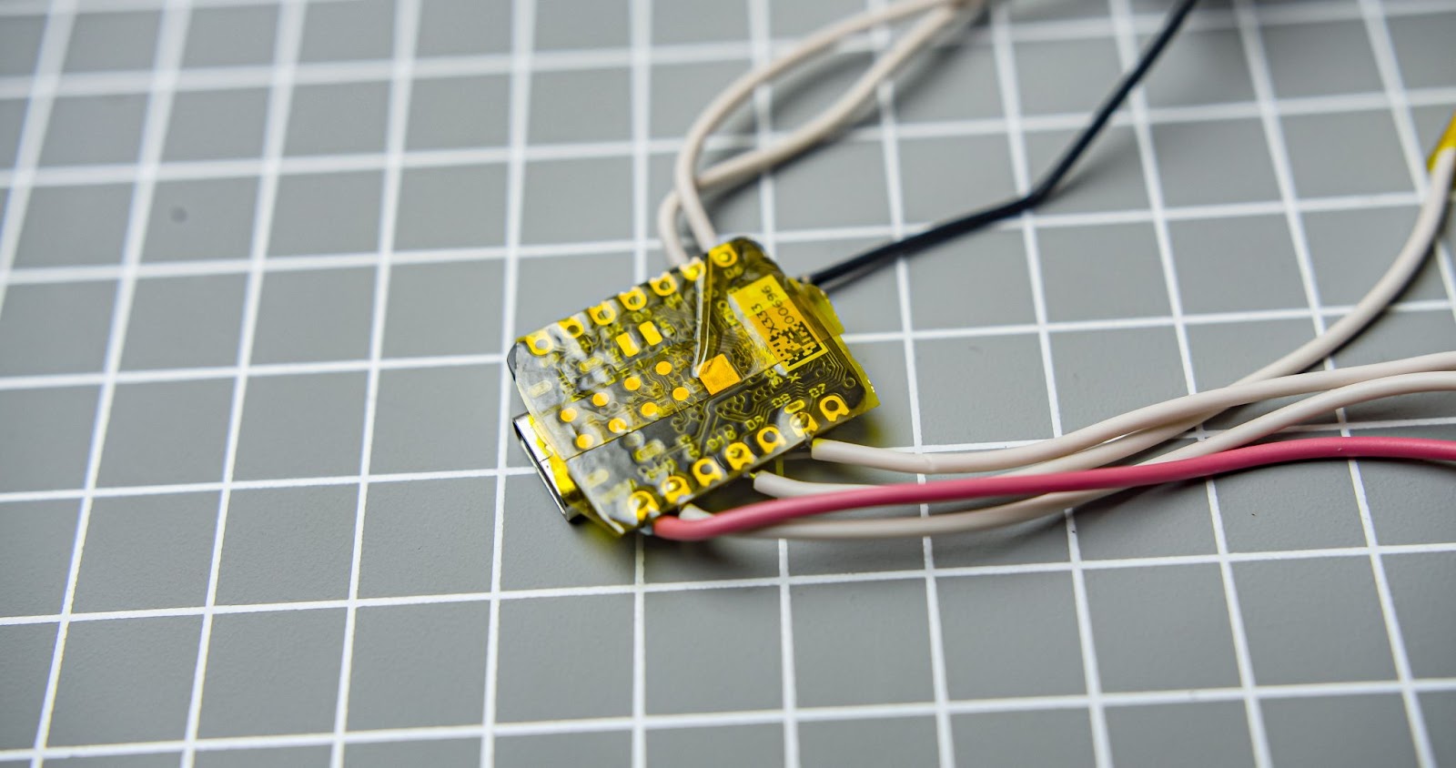
Step 5
Put some heat sink compound to the big heat sink
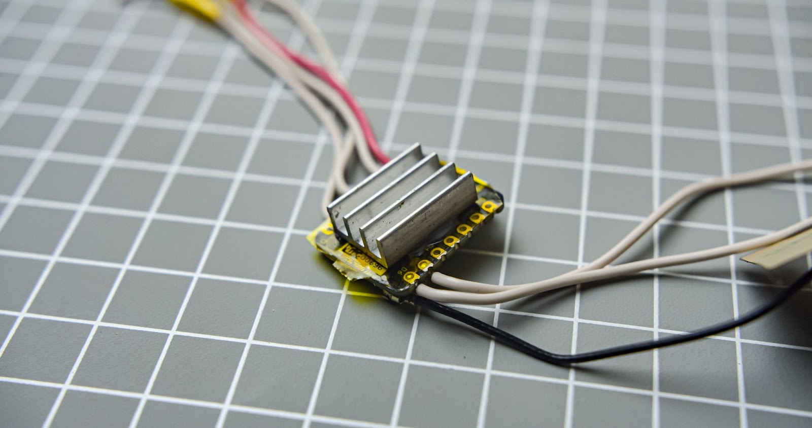
Step 6
Put that heat sink to the back of Xiao
Step 7
glued Xiao to the main body and also put the small heat sink to the camera module
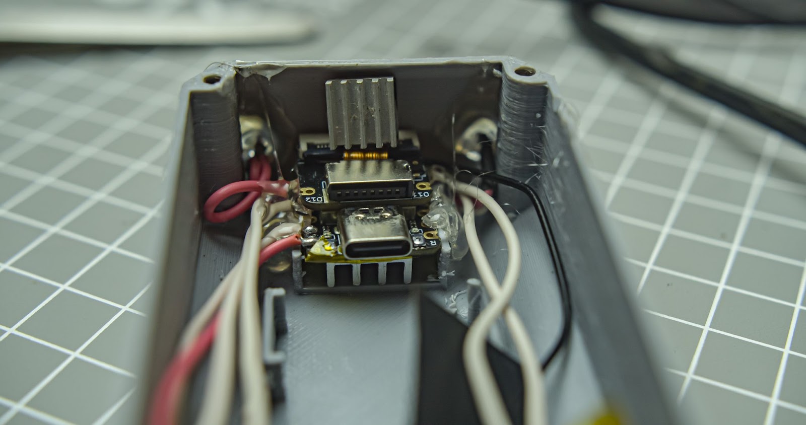
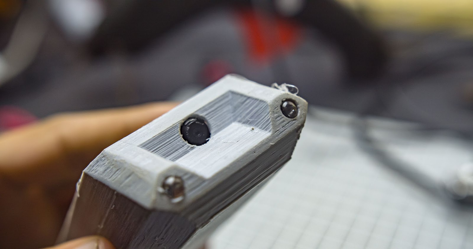
Step 8
Make sure that the camera module is visible through the front hole
Step 9
Remove the sticker on the back of the antenna and past it to the main body 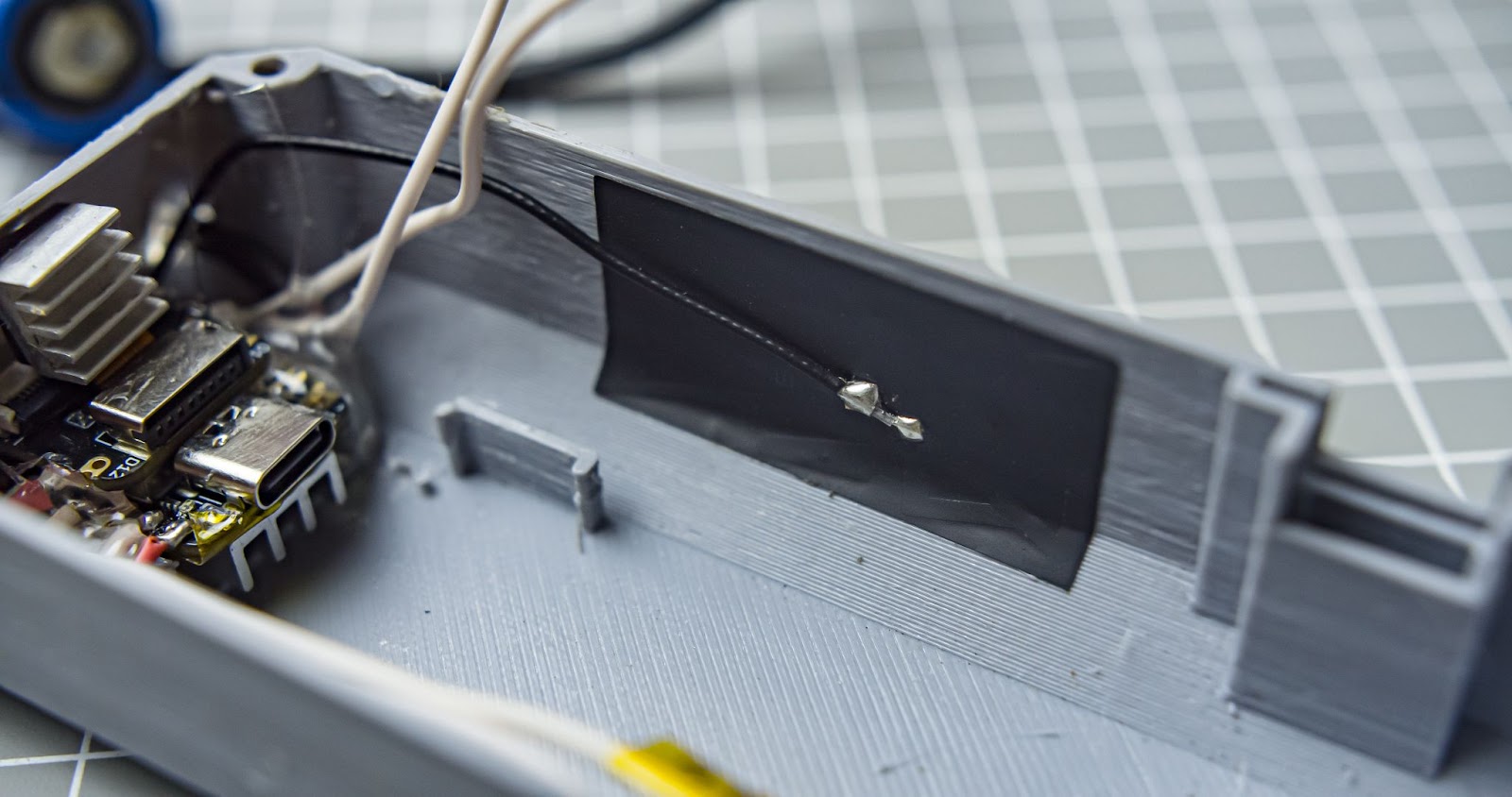
Step 10
connected two batteries in parallel. and connected bms to it, everything is attached together with hot glue 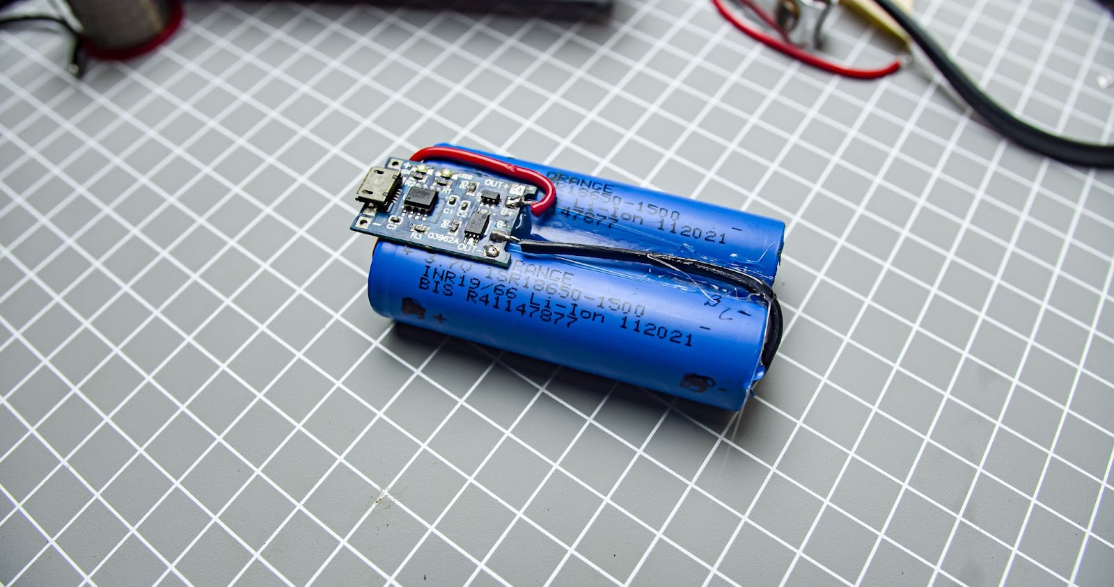
Step 11
Glued the battery to the main body
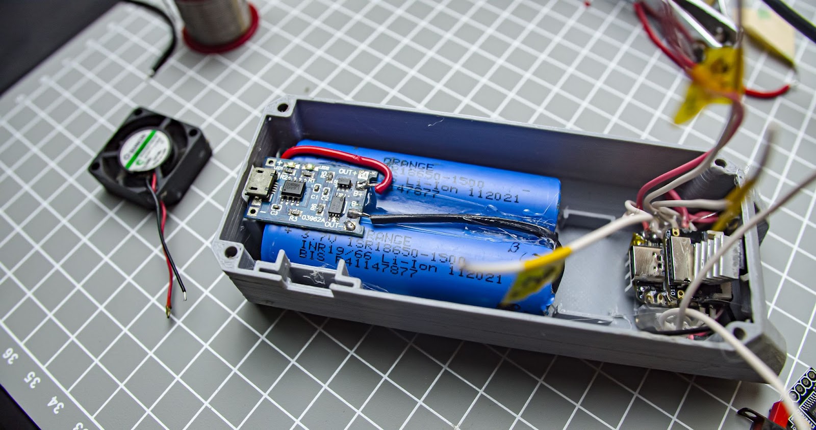
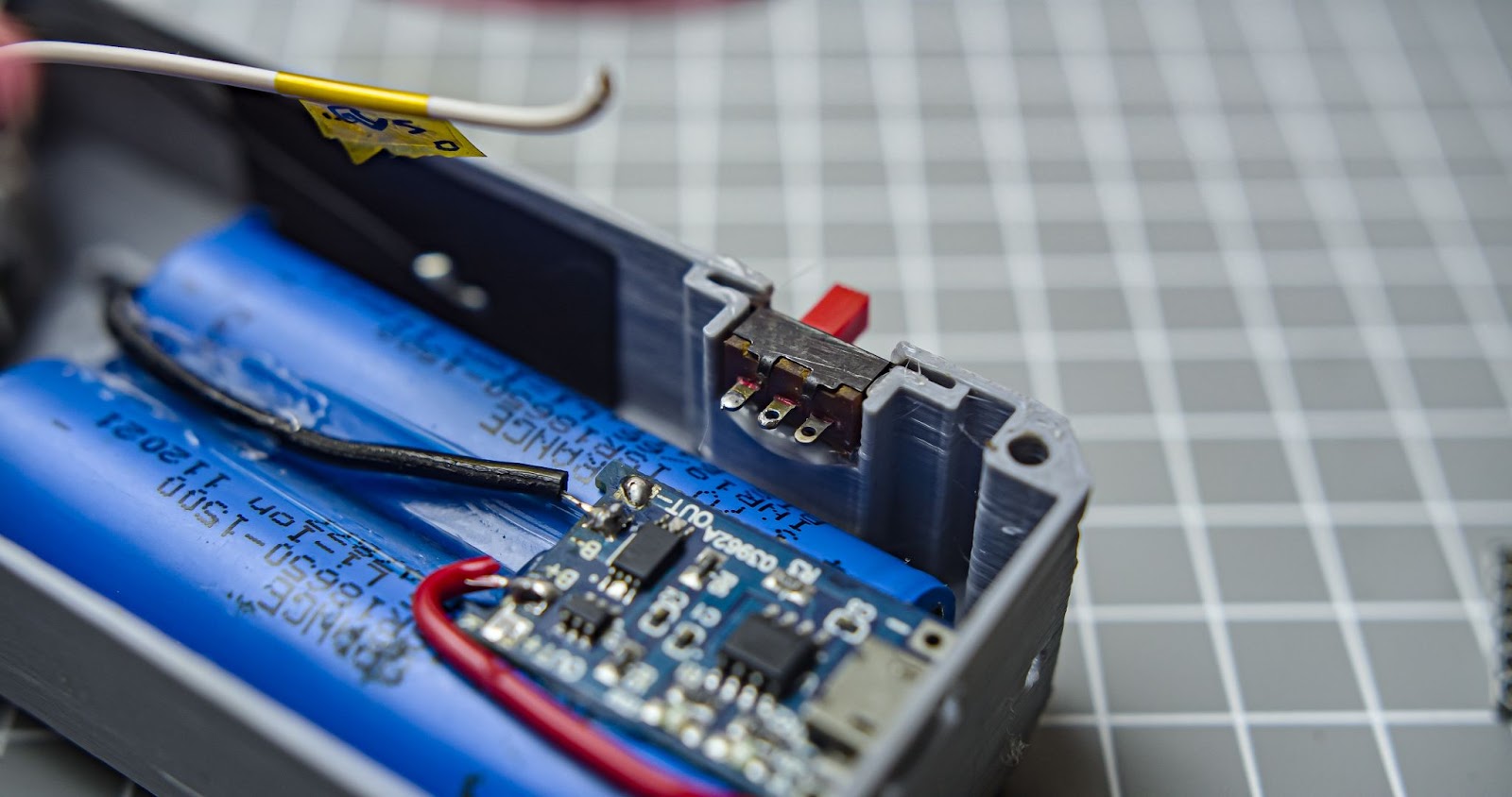
Step 12
Attach the ON-OFF switch to the main body
Step 13
Attach the small fan for the main body
Step 14
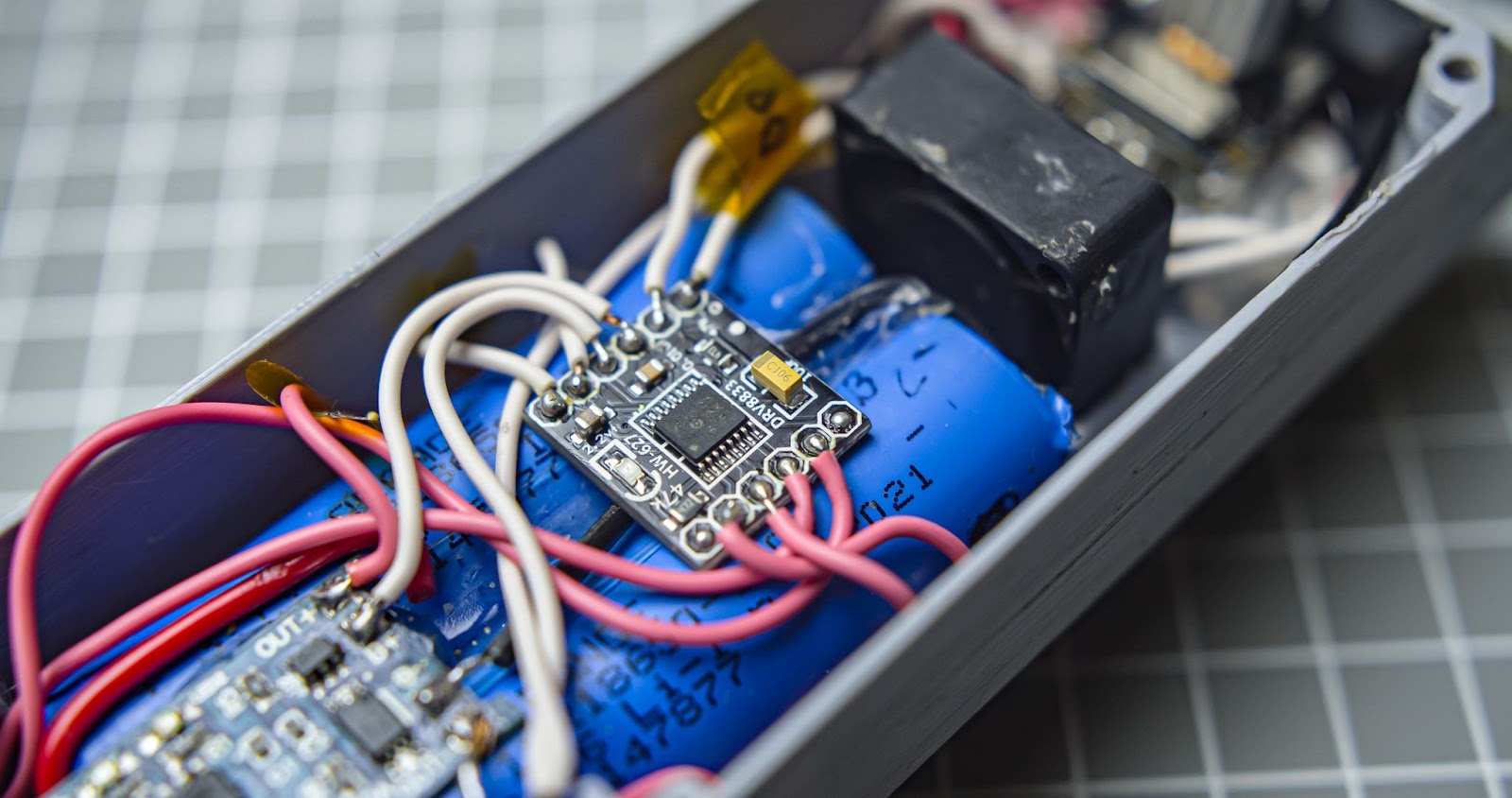
Glued the DRV8833 on top of the battery and connected all wires according to the circuit diagram
Step 15
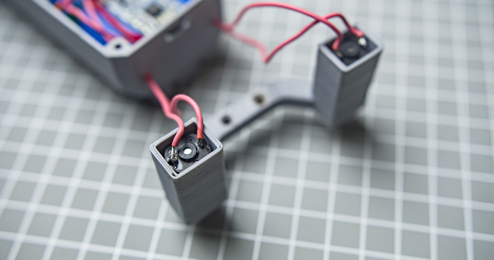
Run the motor wires through two small holes in the back of the main body and connect the wires to two motors
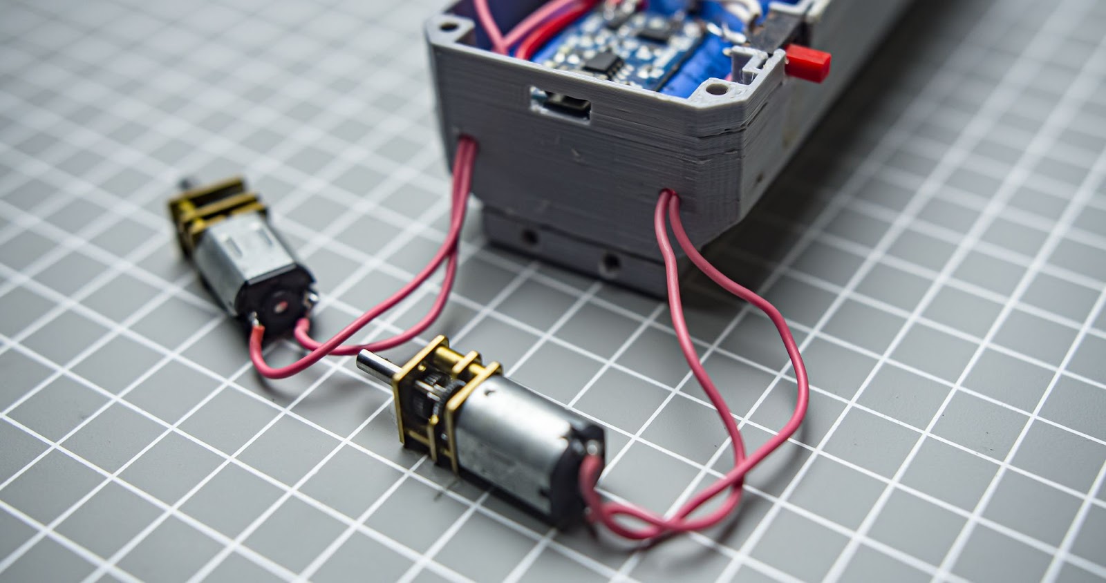
Step 16
Insert the motors in the square holes in the motor holder
Step 17
Attach the back support with four M3 10mm screws
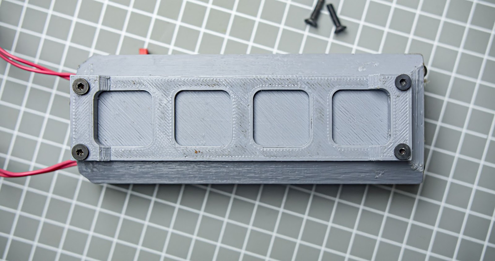
Step 18
Attach the motor holder to the back support two M3 10mm screws
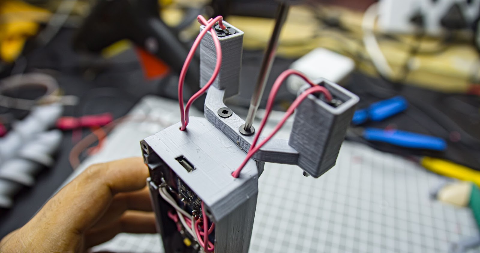
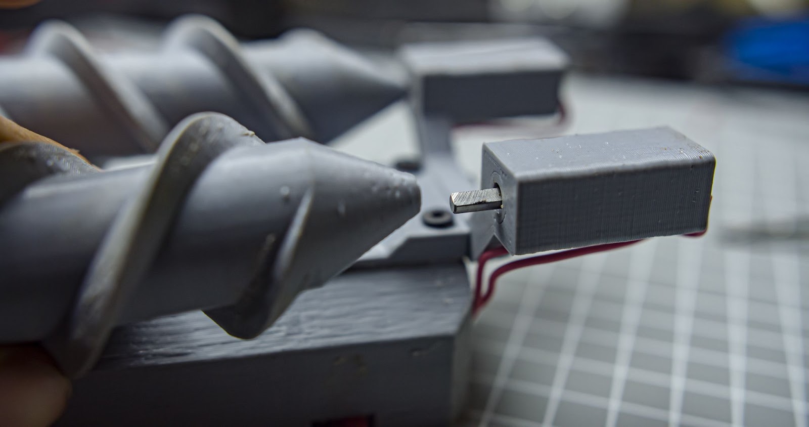
Step 19
Attach the left and right wheels to the motor shaft
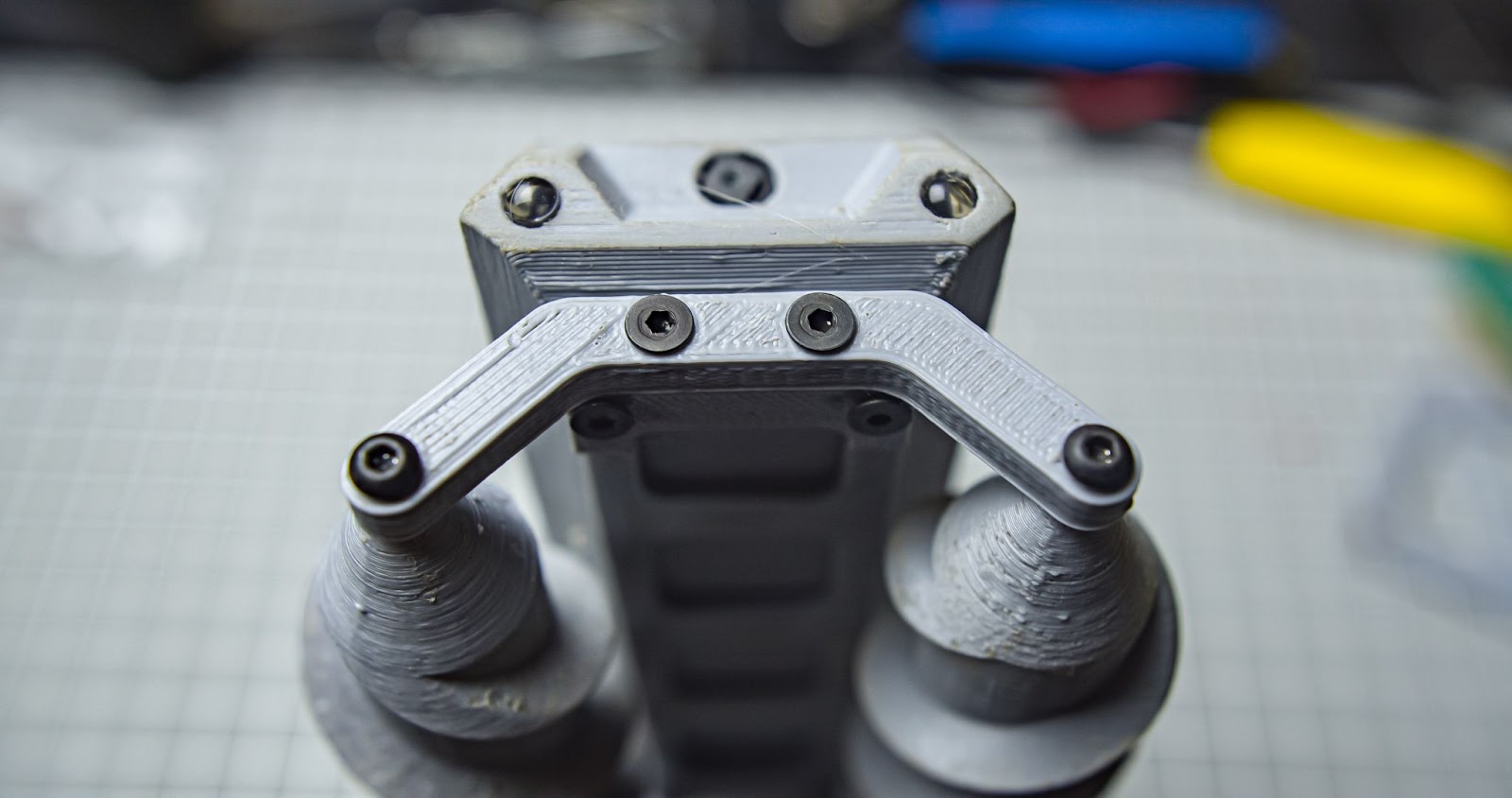
Step 20
Attach the font wheel support to the main body with two M3 10mm screws, and attach the left and right wheels with two M3 20mm screws to the front wheel support
Step 21
Attach the top plate with four M3 10mm screws
Assembly completed, mission successful🔥🔥
Step 9: Testing the Motor Direction
Connect the robot with the smartphone wifi ( step 6)
flip the robot upside down and observe the motor rotation direction, make sure it is rotating as shown below when you press the left and right button
forward and backward test
you can also test LEDs with LED on and off button
if not all motor is turning in the direction you intended, please check the wiring or you can change the motor turning direction within this code line of app_httpd.cpp, change the values in the WheelAct (high/low)
static esp_err_t go_handler(httpd_req_t *req){
    WheelAct(HIGH, LOW, HIGH, LOW);
    Serial.println("Go");
    httpd_resp_set_type(req, "text/html");
    return httpd_resp_send(req, "OK", 2);
}
static esp_err_t back_handler(httpd_req_t *req){
    WheelAct(LOW, HIGH, LOW, HIGH);
    Serial.println("Back");
    httpd_resp_set_type(req, "text/html");
    return httpd_resp_send(req, "OK", 2);
}


static esp_err_t left_handler(httpd_req_t *req){
    WheelAct(HIGH, LOW, LOW, LOW);
    Serial.println("Left");
    httpd_resp_set_type(req, "text/html");
    return httpd_resp_send(req, "OK", 2);
}
static esp_err_t right_handler(httpd_req_t *req){
    WheelAct(LOW, LOW, LOW, HIGH);
    Serial.println("Right");
    httpd_resp_set_type(req, "text/html");
    return httpd_resp_send(req, "OK", 2);
}


static esp_err_t stop_handler(httpd_req_t *req){
    WheelAct(LOW, LOW, LOW, LOW);
    Serial.println("Stop");
    httpd_resp_set_type(req, "text/html");
    return httpd_resp_send(req, "OK", 2);
}
Step 10: Final Thoughts
thank you for going along with this project, i still like to improve this project I am planning for a second version of this robot, a more powerful full motor and fully weather-sealed body, i still couldn't test this on snow because of the geographical limitations, there is still room for improvement, let me know your suggestion
Grand Prize in the
Robotics Contest


