

Introduction: 4" Seven Segment Display

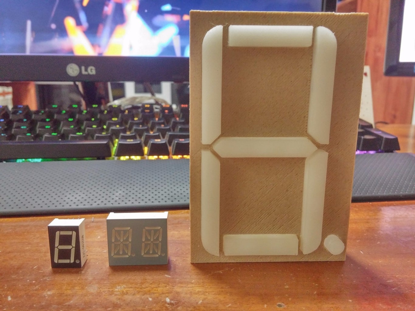


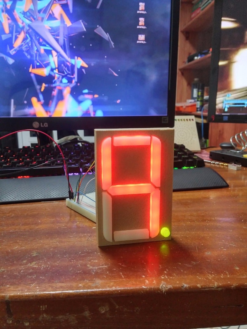
A seven segment display is a basic display which is made up of LED's arranged in a particular order to display numerical values. They are also able to display a lot of the alphabet but not with very good clarity. As the name implies, this display has 7 segments labelled A through G and labeling is done in alphabetical order going in a clockwise direction. They are very basic and easy to use displays however they come in very small packages. I decided to make a large ~4" version which is great to use on walls and makes an awesome clock, temperature monitor or maybe use it to display the number of unread emails in your inbox!
Step 1: Parts and Tool List


The list of parts is very short since this is a basic project. You will need the following:
- Soldering Iron & Solder
- 3D printer & Filament
- Wire Cutters
- Super Glue/Hot Glue
- 20 5mm LED's of your choice (Diffused Preferably)
- Resistors (~100 - 330 Ohm)
- Heatshrink Tubing
For the filament, I suggest two colours, the one has to be a natural/transparent filament and the other can be any colour you choose, I went for a WoodFill Filament.
For the LED's, you can choose any colour you wish, including RGB! I used a bi-colour LED since I didnt have diffused RGB LED's.
Step 2: Printing the Parts

You can download the 3D stl files from my thingiverse page here.
There are 6 files that make up this display however some parts need to be printed twice.
Print the 7_Segment_Display_Frame, 7_Segment_Dot and 7_Segment_G stl files just ONCE. The rest of the parts need to be printed TWICE each. You will notice that the file name corresponds to the correct layout of a generic 7 segment display.
Print Statitics:
7_Segment_Display_Frame:
Speed - 50 mm/s
Infill - 30%
Raft and Support - None
Print Time - ~2 Hours
Rest of the parts:
Speed - 50 mm/s
Infill - 50%
Raft and Support - None
Print Time - ~15 Minutes for each piece
Step 3: Assembly
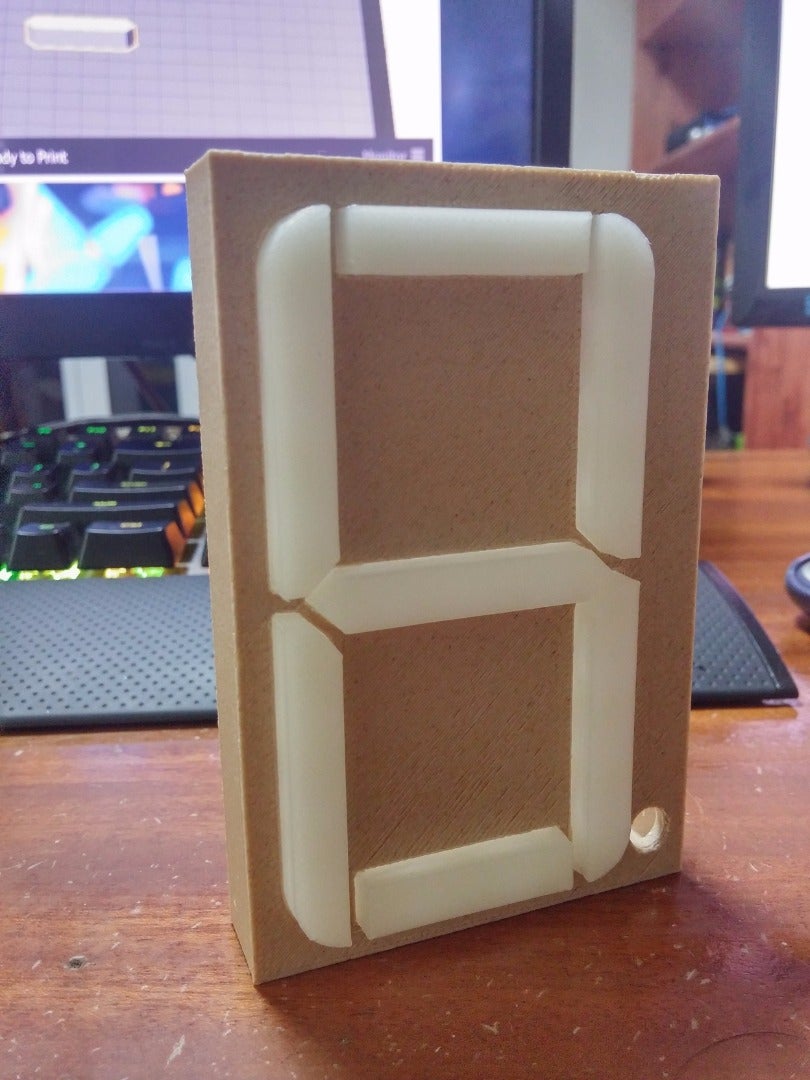
The next step is very simple, use some super glue or any glue you have that will glue plastic, and glue all the segments to the display frame. Simply slide each piece into its correct spot, don't worry about orientation, all the parts are either duplicates or mirrored so it wont matter as long as the shape is correct. If the fit is too tight, just sand down the edges and it should fit nicely.
Step 4: Wiring the LED's


This is the most time consuming step but is still very simple. The LED's I used were common anode and the datasheet said the LED's forward voltage is 2.2V. I wanted my display to work with Atmel MCU's so I chose current limiting resistors based on whether or not the MCU could drive the segment without a transistor or MOSFET. I used about 12mA per LED which isnt very bright. To calculate the resistor, the formula is (VCC-Vf)/I. So my example would be (5-2.2)/12mA = 233Ohms. I just used 220 Ohms since its the closest I had. You can download my app for Android which will automatically calculate the resistor to use. Download it here, It has good reviews and a 4.3 star rating so it is reliable. We have to use a resistor for every LED so we need a minimum of 20 resistors.
You can determine if your display must be common cathode or common anode, for explanation purposes I will be describing common anode.
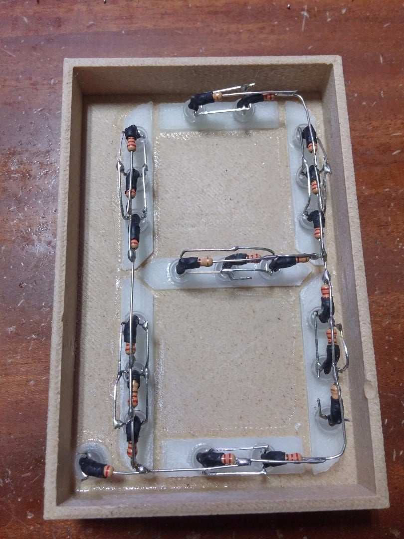
The best way to do this is to cut one of the LED leads shorter. For my LED's, I cut the common anode. You also want to cut one of the leads shorter on the resistor as seen in the above images. Tin both the leads and solder the resistor to the LED. We basically replaced the common anode lead with a resistor, its nice for space savings. Next is to apply heatshrink tubing over the joint to prevent short circuits.
Lastly we glue each LED into its socket of our 3D printed material, I used super glue. Now you want to bend each lead of the LED and wire them up in parallel so all the anodes are connected to each other and all the cathodes are connected to each other. Now some things to note, we still need 7 segments so do not wire up every cathode to every other cathode otherwise when we apply voltage, all the segments will be lit up. Because we are dealing with a common anode display, we wire up all the anodes together, this includes all the anodes from every segment. We do this because we want just a single anode to save wires. The cathodes are a bit different, every cathode in a specific segment needs to be joined together. Every segment has its own separate cathode so by the end of the wiring, we should have just one single anode wire and 7 cathode wires excluding the dot. With the dot, it should be 8 cathode wires. Take a look at the images above to grasp a better understanding.
Step 5: Finishing Up and Ideas
And that's it for this Instructable but not for you. I did provide a back plate to cover up all the LED's and wiring however its very generic. I suggest you drill some holes for the wires, maybe create a special connector, add holes for mounting to a wall etc. There are many things you can do with this display hence a generic back plate, you guys can modify the design to your liking and application. If you want an even larger display, just throw it into a 3D Program and scale it up, however keep in mind that the holes will also be larger so you'll need to use hot glue to hold the LED's in place.
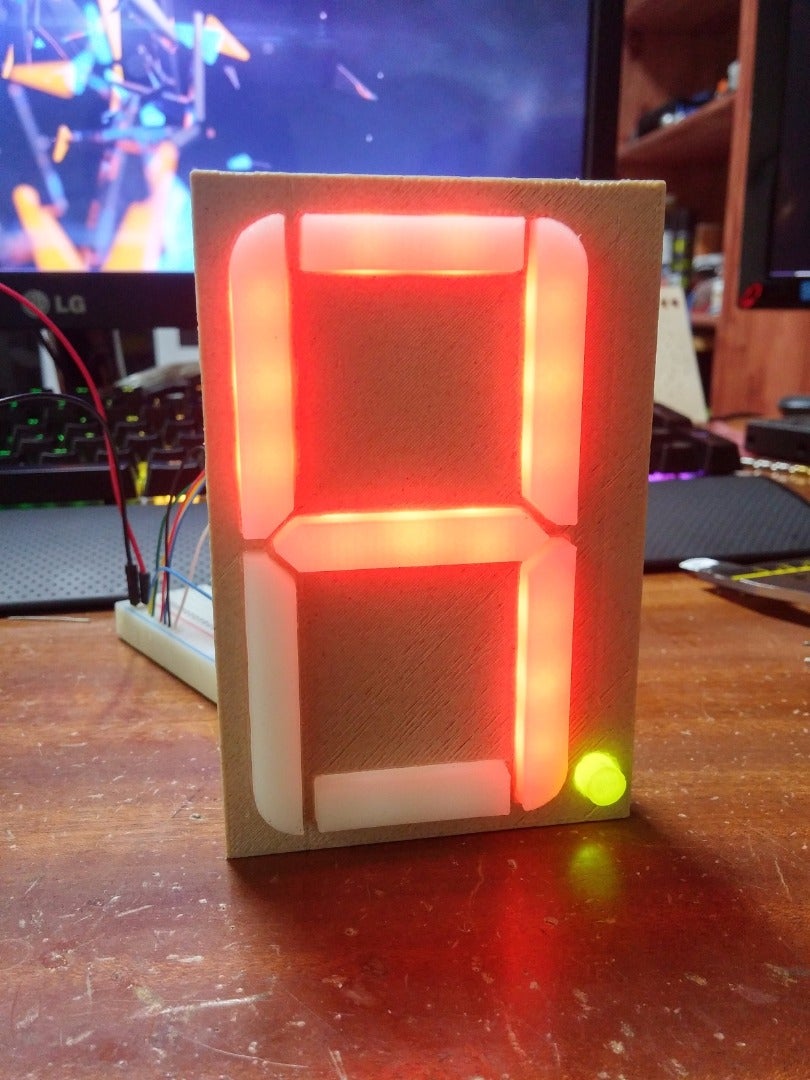
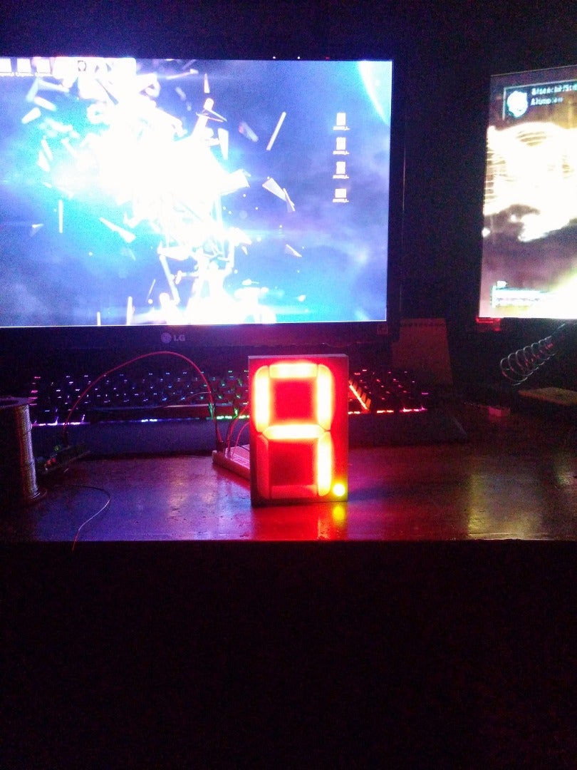
I suggest pushing more current through your LED's, maybe at the full 20mA per LED if you can afford to use up so much power. I say this because it will be much brighter and evenly lit which makes it easier to identify the number being displayed.
A few ideas for this display:
- Temperature Monitor
- Digital Clock
- Stop Watch
- Gym Timer
- Notification Display
- Number of Twitter Followers per day
- Unread Messages
- Tasks to do
Please report any typos or grammatical errors so I can fix them ASAP :)

Participated in the
Soldering Challenge


