

Introduction: 5-axis Minitech Mill Mach3 to LinuxCNC Conversion

I am a third-year electrical engineering student at Stellenbosch University, South Africa. I come from a background where my father is very active with CNC machines. I have recently developed an interest in simultaneous 5-Axis machining and happened to obtain a second hand 5-axis micro mill as a birthday present. The machine is in working condition running Mach3 motion controller software on an old windows 7 PC with 2 parallel ports. Mach3 has a number of problems regarding reliability, ease of use, cost, lack of further developement, lack of 5-axis support and an outdated user interface. I wanted to convert it from Mach3 to open-source Linuxcnc running on a Raspberrry Pi 4. The process followed should provide a high level overview of the conversion steps irrespective of the specific mill or router used and what kinematics it requires.
I want the converted system to be modular enough to disassemble and use on other CNC machines without significant changes in hardware.
Supplies


A number of components are required. Substitute if necessary. In my case:
Current system:
- Old Minitech micromill and accompanying Windows 7 PC and parallel port controller boxes.
- Astro E500z Independent high speed spindle and controller box
New components:
- Raspberry Pi 4
- Mesa7i76e FPGA controller board (manual)
- 5 DM542s Cloudray stepper drivers
- 24 V PSU (for Mesa Card)
- 48V PSU (for stepper controllers)
- Aviation plug pairs
- 5x4pin (stepper outputs)
- 1x8pin (general spindle output)
- 1x6pin (limit switch inputs)
- 220V mains plug
- 19 inch rack and tuffnol sheets (enclosure)
Step 1: Verify Existing Hardware


Firstly, examine your current setup. It may or may not be operational. Figure out what parts can be used what must be replaced. It is useful if you can obtain some of the old configuraion parameters such as the steps/mm gain and the machine extents from the Mach3 machine profile.
The old system contained two integrated control boxes with parallel port inputs, 4 stepper driver outputs and integrated analog power supplies. The electronics within these boxes exist primarily to create a link between the low power signals from the PC parallel port and the high power required to drive the stepper motors. Little additional processing is done. The interface is via Mach3 on an old windows 7 pc.
It is inconvenient to run a system like this as most of the hardware is not compatible with more modern machines and parts are difficult to replace in the event of hardware faults. I will replace both the PC and the control boxes. Although I will be using new stepper drivers, the old Gecko stepper drivers are perfectly usable.
The spindle and driver is a separate unit produced by a different company. The old system required manual spindle control. It would be convenient to integrate the spindle controller with the new control card for programmatic control.
Step 2: Load LinuxCNC on Raspberry Pi 4

A PC is required to run the LinuxCNC operating system. Linuxcnc was designed around the need to have the reliable timing needed for hardware pulse generation. This is opposed to a Windows PC that does a large amount of "stuff" not required to run a CNC machine at the cost of having less reliable timinig. A low cost PC or Raspberry Pi 4 can be used to run LinuxCNC. Instructions on how to do the install are present on the Linuxcnc website:
Step 3: Design the Electrical System


Follow your controller card manual when designing your controller circuit. Some pin jumpers may need to be moved.
Your chosen controller card should support 5 or more stepper driver outputs. These will be wired to the stepper controllers to serve as the bridge from the low voltages on the card to the high power requirements of driving stepper motors.
The Mesa7i76e should receive power from the 24V DC supply while the stepper drivers receive power from a separate(Isolate EMI noise generated by stepper drivers) 48V power supply.
The limit switches are each wired to an input in a NC configuration. The common terminal of each is wired to the field power (24V).
The spindle signals are very dependent on which kind of spindle and controller/VFD you use. On my system, I used an enable signal output, 0-10V analog speed control output and a fault signal input.
Add additional inputs and outputs for required peripherals such as a pendant, LCD displays, pressure detectors, temperature detectors, relays and so on. These can all be read or manipulated programmatically in LinuxCNC.
Verify what type of inputs and outputs are available on you controller card. Some might required pull-up resistors or inverted logic to function correctly.
Only design the schematic for now. The wiring is easier once the components are at fixed positions.
My scematic is included as reference.
Step 4: Design and Build Controller Enclosure


The enclosure will form the base of the new system. Good design is critical to ensure that the layout is intuitive and can be easily reused or fixed after a year's worth of inactivity. In my case the enclosure will only contain the main control board, 5 stepper drivers and 2 power supplies.
I used a 19 inch rack as the container with tuffnol (electrical insulator) sheets to hold the pieces together. The basic interior layout was designed with Fusion 360 and machined on the tuffnol sheets with a router. If a 3d printer is available, it is useful to test-print the footprints (only a couple of layers) of the mechanical components to ensure correct dimensions.
The front panel has to hold items for user interface like the e-stop, programmable buttons and possibly a voltmeter to ensure the system receives power. It is advisable to plan in advance which of these might be useful in the future and include easy breakouts holes.
The back sheet will facilitate the connections between the electronics and the outside world via aviation connectors. 5x4-pin connectors are required for the stepper driver outputs. 1x6-pin connector will handle the 5-limit switches. A 220V mains plug is required to feed the two DC power supplies (CAUTION: they are well-labeled but seek advice from someone experienced).
An 8-pin connector hole was also left to connect the spindle controller.
Many cables have to be soldered and made up. Use of shielded cables is highly recommended to prevent hard to locate EMI problems(Limit switches trip spontaneously) later on. These crimp connectors work quite well for neat screw terminal connections:
A dxf of the panels attached to my enclosure are included for reference.
Attachments

Step 5: Test Controller Enclosure
After assembly of the enclosure, it should be tested on the bench to ensure the wiring is correct. First be certain that the mains power is correctly wired. Disconnect and test the power supplies to ensure the correct voltages are being generated. Test incrementally from there. Have the Raspberry Pi 4 on standby and connect via ethernet cable. Have a spare stepper motor available to test each of the stepper driver outputs. Be sure to set the microstepping consistently on the stepper drivers and check the current (Amps) setting if the steppers do not turn or behave erratically.
Use PNCconf within LinuxCNC to check each of the stepper driver outputs. Usually the limit switches are only added and tested after the axes of the cnc machine are moving.
It is perhaps convenient to create a dummy configuration to test aspects of the system.
Step 6: Disconnect Old Hardware and Connect New System


Now for the permanent step. Commit and cut the wires on the stepper motors at an appropriate place. Replace the previous connectors with aviation plugs. Move away the old hardware.
Plan how to place the new hardware conveniently(Raspberry Pi, Controller box, spindle Box). Add a monitor, keyboard and mouse. Connect everything up. Start the Raspberry Pi and control box.
Step 7: Setup 4-Axis Configuration on LinuxCNC
The LinuxCNC configuration wizard PNCconf(For Mesa Control cards) only supports up to 4-axis machines with trivial kinematics. Follow the given instructions to setup your system. Use the Axis Interface. Set-up according to instructions and verify that all stepppers turn. Set up card connections, gains, machine specific systems. Axis directions can all be flipped in software.
Most of the configuration settings are input here.
PNCconf will generate a folder containing a .HAL and .ini file as well as a executable for your setup. Multiple of these can be kept. Click on the short-cut on the start screen, start Axis and verify that your XYZA axes are operational.
Step 8: Add Limit Switches


Optionally add limit switches to the axes. Failure to do this will require manual alignment on every startup or moving the axes by hand to startup positions before power on. While possible, this quickly becomes very frustrationg. Use 3d-printed brackets if possible. Don't be afraid to add and tap holes on the frame of the machine. Check where it is safe to drill. Wire the limit switches as normally closed (NC) to show broken wires when they occur. Add capacitors to the terminals to filter out possible EMI noise resulting from switching. Go back to PNCconf and edit your setup to include a homing sequence(z first, then all else) and set the machine origin. The exact position is trivial but should be convenient for quickly setting the machine for a job after startup. It is useful to set the Y-zero in line with the A-axis.
Step 9: Cut a Bit

Skip this step if you are brave enough to tackle the software edits and matrix math. Otherwise, gather some motivation for the task ahead, do a bit of CAD and CAM and generate some gcode.
Fusion360 can do indexed 4-axis machining with a regular or student license (possibly the free hobby license as well). Vcarve Pro can wrap 3d models around a rotary axis and do 2 linear + 1 rotary machining. This is useful for items like chess pieces.
Ensure you are comfortable with the current machine setup. Use PNCconf as necessary.
Step 10: Enter .Ini and .hal

Unfortunately PNCconf only works up to 4-axes. Note that any changes to these files will be overwritten if PNCconf is used to edit the setup again.
Duplicate the setup folder to ensure easy recovery if unforeseen difficulties arise. Open the ini and HAL files (in Notepad).
Duplicate the AXIS A JOINT 3 section in the HAL file and rename the applicable variables to AXIS B JOINT 4. Do the same with the [AXIS_A] and [JOINT_3] sections in the ini file. Modify a few other settings such as "num_stepgens=5"(HAL) and "[DISPLAY]GEOMETRY = xyzab, [KINS]JOINTS = 5, coordinates=XYZAB, [TRAJ]COORDINATES = XYZAB" (ini). Read through both these files and modify anything that seems specifically related to 4-axes. Some understanding of these files is useful. A quick read on the basic way HAL works. Detailed documentation is available on the LinuxCNC website.
Attempt to start the exe. Ideally it should open Axis and allow movement of all 5-axes if they are connected and described correctly in software. Errors on startup may occur but shouldn't be excessively difficult to remedy. A line or two near the end of a long log should describe the issue. Manually modify the HAL and ini file sections describing the B-axis by example of the other axes to ensure soft limits, hard limits and homing function correctly.
At this point you should have a fully-functional 5-joint machine with trivial kinematics.
Step 11: Kinematics


Kinematics are tricky in concept and difficult in interpretation but the maths is relatively straightforward.
Note that a joint is the range of movement associated with a single stepper turning while an axis is defined as a change in position or orientation of the cutting tool tip relative to the stock. With axis movements either the tip moves in XYZ relative to the stock while its orientation is fixed or the tip position is fixed relative to the stock while the tool rotates about the tip (no mention of what the steppers do).
Directions are defined using a right-handed coordinate-system from the point of view of the stock. ABC axes directions correspond with the XYZ axes according to the respective right hand rule.
You will have noticed that the tip of the tool moves relative to points on the stock even when a rotary joint is used. Generally, it is easier to program a CNC machine in terms of the position and orientation of the bit, rather than the required position of each stepper. For this purpose, the CAM program is usually split from the steppers(joints) via a separate program (written in C) doing calculations to transform from axis-coordinates to joint-coordinates (inverse transformation) and possibly vice versa (forward transformation).
A kinematics file describes the specific way the movable links between tooltip and stock are arrranged. Several kinematics files for 5-axis machines are already available in standard Linuxcnc and can be used as is by specifying "[KINS]KINEMATICS =..." in the ini file. The trunnion table (AC-axis on table) is generally the most common. If yours is availble, ignore the rest of this step.
In the unlucky event that your machine kinematics is not directly available, you will have to try to find a kinematics file online or derive it yourself.(Requires some knowledge of matrixes and C but not impossible.)
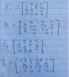
A manual here or here on doing the derivations and code implementation is available. My machine has a A-axis on the table and a rare B-axis on the head. Photos of tested kinematics for this machine are included. "s" and "c" represent sine and cosine.
Mathematically, this involves drawing a sketch to show the chain of coordinate system-links (vectors) between the stock and the tool-tip. Each of these vectors can be represented by a transformation matrix which are multiplied out to find the transformation equations. These will contain offsets which may be variable (position of a joint) or constant (alignment length).
Use a standard kinematics file from the LinuxCNC Github as a template and add your forward and inverse transformation equations. Offset parameters such as tool length required for correct position can also be communicated between axis interface and kinematics file through HAL variables.
After the initial draft has been written in C, transfer the file to LinuxCNC and either look into Vismach simulations(machine models built in Python) or run on your own machine (Remove expensive components and ensure rapid movements will not crash). Several installations (described in the third link) will have to be done on LinuxCNC to enable compilation of custom kinematics files.
Step 12: Debug Kinematics
Once you've managed to sort out HALcompile and corrected the syntax errors in your c file, you can start witnessing some simultaneous movement. Perhaps replace your expensive spindle with a wooden dummy or pencil. You will likely encounter a joint-following-error. This occurs when the cyclical transformation from axis to joint and back to axis returns a result different to the original coordinates (should be identical). This might be caused by inconsistencies in your equations. If this error does not occur but the movement seems incorrect, either switch a sign in the axis configuration or check whether your sketch was correct.
It is useful to set the rate at which the axis can move relatively slow at first. Axis and joint speed are set separately in the HAL file and if those speeds are too fast the axis may outpace the joint and cause a joint-following-error.
Continue until the tool tip appears roughly fixed when rotating in either direction.
Step 13: Alignment

Use an inclinometer to find level positions for the A and B axes as you would like to define them. Use the positions you would like them to have if you happen to do 3-axis work on this machine. Find the exact Y-offset required to place machine 0 on the A-axis. In my case, the distance between the B-axis and the tip of tool 0 (spindle without tool) had to be found. Enter these offsets into the hal variables created by the kinematics file by setting them as constants in the HAL file. Note that you can verify the existence of these pins and their values in real time by using the "HAL meter" in the Axis Interface while the system is running.
Step 14: Z-Offsets

Generally, the z-position of a piece of stock is referenced by moving a thin sheet (paper or x-ray film ) with known thickness between the bit and the stock as you slowly lower the z-axis. The bit will have a known height relative to the stock when the sheet gets caught. The local coordinate system (G54) can be set appropriately.
Inevitably, you will desire to use multiple bits in a single job. Manually referencing Z0 each time is inconvenient or impossible (reference surface was machined away).
Alternatively, you can find the relative length of each tool by using a touch-off probe, automatically sending the lengths to the tool-table and simply applying the offsets in gcode to change the z-height when a new tool is used. In theory this process is simple. Unfortunately, it tends to cause an unreasonably large amount of confusion and frustration for those trying to understand and implement it.
If you are willing to expend that effort to avoid manual touch-off, buy or make up a z-probe. It's just a button which is pressed when a tool is lowered onto it. Note that its quality and repeatability will influence the precision your machine can achieve.
Find someone who has managed to get it working. Most 3-axis probing routines work by calling a gcode macro, probing the tool and saving the distances to the tool-table using #-parameters. G43 is then used to apply the offsets. Note that these offsets also have to be fed into your kinematics if any of the rotating components are on the head (trunnion table system should work with 3-axis touch-off routine).
My setup works by doing a touch-off routine with an empty spindle(ref tool) while a numeric input box contains 0. G59 coordinate system is then zeroed. Place a tool in the spindle. Probe again. G59 now contains a positive coordinate (relative tool length). I then manually enter this into the numeric input box and it is sent to my kinematics file. Better methods of implementation exist.
Good luck.
Step 15: CAD and CAM
As briefly mentioned in Step 8, a CAD (digital design) and CAM (toolpath and gcode generation) package will be necessary for the operation of your mill. This tends to be a pricy exercise, especially where 5-axis software is involved. Again the Fusion360 hobbyist/personal license may give a temporary solution.
I used Fusion360 CAD and CAM with a student license. This includes (at the time of writing) renewable access to the machining extension and full 5-axis capabilities. Any other CAD or CAM package will do. Many resources are available to assist in obtaining design skills.
Step 16: Post-processor


A Post-processor will be required to convert toolpaths in Fusion360 CAM to compatible gcode for Linuxcnc. The standard LinuxCNC EMC2 post-processor should be sufficient. You will likely need to setup the 4th and 5th axis in the post-processor. The manual for post-processor editing is also available. They are written in javascript.
Note some post-processors may issue a command to make the mill move to a safe position or the machine origin before it starts cutting, possibly causing a colision. Modify the gcode file with Notepad or some other text editor if necessary.
Some post-processors are set-up to do the kinematics transformations for you. This should be disabled or use an AB axis on the head with 0 offsets (corresponds to axis-coordinate system), if LinuxCNC kinematics are used. Fusion360 gcode should only contain tool position and orientation coordinates. You can check the gcode with a free gcode viewer like NCviewer (in non-5 axis mode).
Step 17: Cutting


After many struggles you will finally reach the point where your machine is working once more and hopefully far more enjoyably than previously. Try to get as much experience as possible with the machine. Remember, failures are more instructive than successes. Learn about workholding. Precision will become natural as you become more experienced with the machine.
At the start of testing, use a soft material to prevent damage from stock crashes. I used soft, modeling material and a model of a propeller blade to test the various 5-axis features. Afterwards, I attempted to machine some aluminium with the same model. I used a different mill to cut a cross into the base of the cylindrical stock to ensure the 4-jaw chuck could hold the piece properly.
Step 18: Future Development
It would be convenient to have an enclosure to reduce the noise and chip scatter currently created whenever the machine runs. Coolant could also assist in machining some materials.
My currrent machine profile files are included below for reference. It includes the ini and HAL files, the kinematics file and the macros and pyVCP code for the probing routine. The exe is not included.
Have a nice day

Grand Prize in the
CNC Student Design Challenge


