

Introduction: 64x32 LED Matrix Clock


"I DON’T EVEN SEE THE CODE ANYMORE" - The Matrix.
Here we have a clock that presents the current time on an 64x32 RGB LED using a "Matrix-like" falling particle effect.
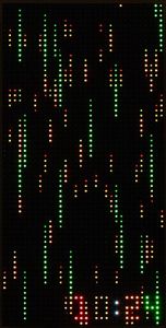
The clock also offers other presentation styles, including an "advanced" matrix that does not show the numbers (you can learn to read the clock based on colors and particle speeds).
Although the images above give you a basic idea, they can't show you the dynamic range of the LED or the visual impression of 200 FPS animations,
The project's firmware is designed to easily incorporate support for other hardware configurations. Included in the code is an 8x8 "Dotstar" matrix version that was my first version. This document focuses on the newer 64x32 model, which I prefer. If you want to learn more details on the dotstar build, I have a separate document for it here.
Supplies
- Microcontroller: Raspberry PI Pico ($4)
- LED Matrix 64x32: ($30) There are many vendors of this display - I assume they have similar hardware.
- Clock: DS3231-based RTC module ($4). This part is optional-but-recommended. The clock's firmware can be built to use the PI Pico itself as a clock but you will lose battery backup and the time will drift more.
- Buttons: I used 2 6 mm push buttons for control (<$1) and one 6x3 SMD button for optional reset capability.
- Connectors:
- I used one right-angle 8x2 2.54 pitch male pin header to connect the Pico to the matrix using the interface cable that is usually bundled with the 62x32 display.
- I used a 2x1 angled 2.54 pitch pin header for connecting the LED power input. Direct solder is an option.
- I used a 3x1 angled 2.54 pitch pin header for connecting the buttons. Direct solder is an option.
- I used a 220 uF capacitor to reduce 5V noise. Somewhat larger or smaller values should also work fine.
- Circuit board for assembling components.
- I ordered a PCB from http://oshpark.com for the main board . I could have wired everything up on perf board, but the large number of pin connections would have made it difficult to get a clean result.
- There is a separate PCB for the buttons. This board is very simple so any build technique should be straight-forward. I used my CNC machine to cut a board within an hour. If you order a main board, you might opt to bundle the button pcb with the order.
Optional:
The LED display can pull over 3 A if all LEDs are set to white. The firmware I wrote never does this and needs about 100-300 mA for most of the modes (as-measured with a multimeter). Thus I'm using the Pi Pico's VBUS pin, which is directly-connected to USB power. This connection should be limited to 500 mA or less, thus I added the following electronic components to enforce the current limit:
- NCP380 current limiting IC.
- Two additional 1uf capacitors for stability. I am using SMD capacitors but ceramic through-hole are also an option.
My hardware has this current protection but it has never activated outside of testing. One might therefore argue that it's not needed. If you plan to make your own display modes, I suggest including the protection.
Step 1: Feature Overview
Reading The Clock
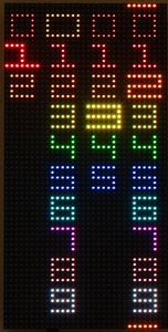
How can the clock be read when no numbers are shown? By noting the colors and speed of the particles. The "time set" interface image above shows my color mapping for each number:
Colors are defined in src/colors.c if you would like to edit them.
Setting the Time
The clock has two buttons on its bottom: "set" and "increment". Pressing "set" goes into time change mode where you can use "set" and "increment" to change each time digit.
You can also set the clock via the USB connection.
Changing the Display Mode
If you press the "increment" button while the matrix is showing, the clock will cycle through display modes. Currently defined modes include:
- Matrix With Numbers: The default.
- Matrix Only: For those who want a challenge.
- Bounce: Particles bounce around the numbers.
- Number Cascade: Digits fall from the top of the display to the bottom. The size and speed of the digit represent the place in the time (hours vs minutes).
- Waveform: Waveforms progress from the bottom of the display to the top at different speeds.
- Drops: A water droplet effect appears behind the numbers.
- Off: Useful if you want a darkened room.
Each display mode uses color as described earlier to accent the current time.
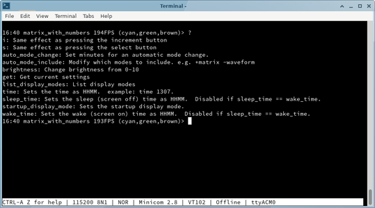
Console Configuration
If you plug the clock into a computer, you can run a terminal emulator program to access many additional settings. In Linux, I use the "minicom" terminal emulator and my command looks like this:
minicom -b 115200 -P /dev/ttyUSB0
Once started, you will see something like the console image above. Type ? for help.
By default, minicom turns on local echo, making my typed characters appear twice. minicom allows local echo to be toggled off with ctrl-a e.
The serial device path (/dev/ttyUSB0) can vary between computers and operating systems.
Step 2: Electronics


The image above shows the main board schematic. Here is a description of major components and their purpose:
- Pi Pico: This is the main controller.
- RTC (Real Time Clock, Optional): This provides time to the Pico via an I2C connection. You could use alternate clock hardware as described in a later section. In terms of the I2C connection, note that the RTC clock is powered by 3.3V instead of 5V. This is the easiest way to make the clock compatible with the 3.3V maximum voltage of the PI Pico. If your RTC really does need 5V, there are solutions but the details are not the focus of this document. Thus I suggest doing a Google search for "3.3 to 5V I2C" to learn more.
- 64x32 LED matrix: This is also a 5V part and is connected to the 5V VBUS pin of the Pico, allowing ~500mA to be safely consumed by the LEDs. The Pico has directly connected GPIOs and will deliver 0-3.3V signals to the LEDs. Unlike I2C for the RTC clock, the LED control pins are high impedance inputs with no pullup thus there is no hardware risk to the Pico. The main risk is that the LED panel will not accept 3.3V as a legitimate "high" signal and thus it wont work. For my panel, 3.3V was accepted without a problem thus no level converters were needed. I suspect this is the common scenario with these panels.
- 100 uF - 470 uF capacitor. The actual value is not important other than "big". The purpose of the capacitor is to support the power requirements of the LEDs, which can be a "noisy" load, needing near zero current one moment and several hundred mA the next.
- Buttons: Select, increment and reset as described earlier.
- NCP380 current limiting chip (optional): This chip provides insurance for the case where you one day decide to change the firmware to light up many LEDs and draw too much current. If you want to support high current draw, you'll need to rework the power design so that the LED panel is directly powered from a capable (3A+) source instead of VBUS on the Pico.
VBUS on the Pico is a direct passthrough to the USB power. Thus it's the USB regulator (wall adapter or computer) and the PCB traces of the Pico that are the main power bottlenecks.
If you decide to use external power, then your chosen 5V power source should connect to the Picos VSYS pin via a Schottky diode. The diode will prevent the Pico's USB connection from trying to power the LEDs and from backfeeding into your chosen power source. Using VSYS instead of VBUS protects the USB power from your power source via a Schottky diode that is already included on the Pico.
If you want to use the Pico's VBUS to power the LED without the protection of the NCP380, simply connect the pin directly to the LED's positive terminal. Keep the 100 uF capacitor for noise purposes.
In terms of layout, an image above shows the KiCAD circuit board layout (with ground plane hidden). Also shown is a photo of the completed PCB. Note that the capacitor can't be seen because it is on the backside of the board.
As for the buttons, a couple more images above show the simple KiCAD layout and the finished board that I cut out with my CNC machine. Using a perf board for the buttons would also work fine.
Step 3: Firmware
Firmware
TLDR: If you don't want to build the firmware (matrix_clock_led_64x32.uf2) yourself, I have a couple of precompiled versions under my github project's firmware directory.
Source files (written in C) are provided in the src/ directory of my github repository. If you have never built PI Pico firmware before, work through the official Getting started with the Raspberry Pi PICO documentation first to get the needed tools up-and-running on your system.
The instructions for building the clock firmware are the same as the guide linked above, but I created a small bootstrap.sh script to lessen the number of needed steps. In Linux or Mac:
./bootstrap.sh
cd build/
make -j
I encourage you to view the contents of bootstrap.sh yourself instead of blindly running it. You'll see something like this:
$ cat bootstrap.sh
#!/bin/bash

if [ ! -f pico_uart_console/CMakeLists.txt ]; then
  git submodule init
  git submodule update
fi

rm -rf build
mkdir build
cd build
cmake ..
If building under Windows, you may opt to run the DOS-equivalent commands contained within bootstrap.sh manually. The good news is that there are only a few commands to run.
The two major things done here are getting some dependencies (git submodules) and setting up a new build environment under build/
If all went well above, you will have a src/build/matrix_clock.uf2 file available to load onto a PI Pico. Note that firmware/matrix_clock_led_64x32.uf2 will not be changed.
Step 4: Build


The hardware build is fairly minimalistic, solving the given problems:
- Securing the PI Pico, RTC hardware and buttons to the LED panel.
- Keeping the connection cables constrained so the clock can mount flat on a wall.
- Providing a wall mount.
I solved all of these problem by creating a couple of 3D models and printing them out. I used the free OpenSCAD software for the modeling.
If you don't have access to a 3D printer you can solve the problem using wood strips painted black with openings cut as needed. More wood strips and zip ties can hold components in place. It only needs to look good on the sides as the back will be against the wall.
This model is located at case/led_matrix_64x32/led_matrix_64x32.scad. It can be modified with any text editor.
If you don't want to mess around with OpenSCAD, I also have the models available for direct download at case/led_matrix_64x32/export. These are .3mf files (the successor to .stl format) that most modern slicer programs can directly load.
To assemble, I used M2 bolts to attach the buttons to the bottom, 6mm long, I think, but something in that area should be fine. I used M3 bolts (around 12-16mm) to attach the 3D printed parts to the led matrix.
The PCB settles into a custom slot in the bottom 3D part (see the grooves in the red image above) and is held in place with no bolts required, just make sure it's in the proper position before tightening the frame bolts.
The hex matrices on the back hold the power and led interface cables within the unit so that it will mount flush on the wall. A guide and slot is provided for wall hanging the unit.
Step 5: Customization
This part of the documentation points you in the right direction if you want to modify the project. This entire section should be consider optional and more advanced than others.
Using Different LED Hardware
The file src/led_matrix.h, contains the interface your hardware driver will be called with. src/led_matrix_64x32.c implements it for the 64x32 LED hardware. There is also a src/led_matrix_dotstar.c file which is used instead when building the dotstar version. To add additional hardware support, create a new .c file (for example src/led_matrix_neopixel.c) and change src/CMakeLists.txt to point to your new file.c`. The main function you'll be implementing is:
#define LED_MATRIX_WIDTH 8
#define LED_MATRIX_HEIGHT 8

// render the matrix.
// data is of the form 0xIIRRGGBB where
// II -> Intensity (brightness)
// RR -> Red
// GG -> Green
// BB -> Blue
//
// Values are 0-255
// format is horizontal rows.  The first pixel
// sent is the southwest corner of the matrix.
void led_matrix_render(uint32_t* data);
Again, look at src/led_matrix_dotstar.c for a straight-forward implementation of led_matrix_render.
Using Different Clock Hardware
Instead of an RTC, you might want to go with a radio-based clock, a GPS clock, or keeping the time with the Pi Pico.
The PICO SDK provides time functions but you'll lose battery backup and accuracy is not as good as dedicated RTC hardware.
src/clock.h gives the interface:
// gets the current time in HHMM format (0000 - 2359)
// For example, if 1354 is returned, the time is 13:54 (or
// 1:34 PM if you prefer)
uint16_t clock_get_time();

// Sets the time.  For example: time_hhmm = 1234 would set the
// time to 12:34.  Note that 24h time is always used so 1234
// is 12:34 PM and 0034 is 12:34 AM.
void clock_set_time(uint16_t time_hhmm);
and src/clock_ds3231.c gives a concrete implementation for the RTC module. The file src/clock_pico_internal.c provides an implementation that does not need RTC hardware. It can be selected in src/CMakeLists.txt.
Adding / Changing Display Modes
There are two files and one directory to consider. The first file is src/clock_render.c. Specifically, this section:
  struct DisplayMode display_modes[] = {
    {"matrix_with_numbers", matrix_with_numbers_render},  // This entry will be the default power-on mode
    {"matrix", matrix_render},
    {"bounce", bounce_render},
    {"number_cascade", number_cascade_hires_render},
    {"waveform", waveform_render},
    {"drops", drops_render},
    {"off", blank_render},  // always put this entry at the end of the list
  };
This section lists the display modes, names them and provides a function pointer to each one. If you were to remove a line from this array, or reorder the lines, you would see the corresponding change when you build/load new firmware. In order for the function pointers to have any meaning, you'll need to include the corresponding files:
#include "render/matrix_with_numbers.h"
#include "render/matrix.h"
#include "render/bounce.h"
...
Note that, by convention, all rendering functions are defined in the src/render directory. Here is an example src/render/blank.c:
void blank_render(
    uint32_t* led,
    uint32_t frame_index,
    uint16_t time_hhmm,
    const struct ClockSettings* settings) {
  memset(
    led,
    0,
    LED_MATRIX_WIDTH * LED_MATRIX_HEIGHT * sizeof(uint32_t));
}
This simple function simply clears the LED array to zero which effectively turns off the display.
The time_hhmm parameter provides the time as an integer. For example, 1:45 AM would be represented as 0145 and 1:45 PM would be represented as 1345.
The frame_index parameter can be useful for initialization. It is always set to 0 when the display mode is made active.
The settings structure has several potentially-useful fields but especially useful is getting the user preference for LED brightness:
const uint8_t br = brightness_step_to_brightness(settings);
This value (0-255), would then be used as a baseline brightness when turning on LEDs.
Changing the Console
The file src/clock_settings.c contains all of the commands available to the USB shell. I suggest skimming through https://github.com/mattwach/pico_uart_console to get up-to-speed on how the console works as it will help in understanding this file.

First Prize in the
Clocks Contest


![Tim's Mechanical Spider Leg [LU9685-20CU]](https://content.instructables.com/FFB/5R4I/LVKZ6G6R/FFB5R4ILVKZ6G6R.png?auto=webp&crop=1.2%3A1&frame=1&width=306)


