

Introduction: Add Bluetooth to Your Plotter


This instructable explains how to replace your USB plotter cable with a bluetooth wireless link.
Your plotter [1] may now be placed in a convenient location that is remote from your computer.
This add-on module is compatible with any arduino circuit that uses a serial connection ... no coding is required.
[1]
The following plotters are USB only and would benefit from bluetooth:
Step 1: Circuit Diagram

The circuit comprises two resistors, an HC-06 bluetooth module, and an arduino UNO R3 microcontroller.
The bluetooth module, and the arduino, both treat voltage levels greater than 2 volts as a logic HIGH, and voltages less than 0.8 volts as a logic LOW.
Resistors R1 and R2 reduce the 5 volt TTL output voltage from the arduino to 3.2 volts to prevent damage [1] to the CMOS chip in the HC-06 bluetooth module.
Removing the USB cable also removes the 5 volt power to the arduino. Power to the arduino is restored by connecting a wire from the external 12 volt stepper-motor supply and the Vin pin on the arduino.
Use a 4-pin socket when wiring the bluetooth module as the HC-06 MUST be removed [2] whenever you attempt to program the arduino ... you can't have two serial ports active at the same time.
[1]
Because the HC-06 uses 3.3 volt CMOS technology all input voltages must be less than 3.6 volts ... preferably around 3.3 volts. The maximum voltage at the HC-06 RXD input is therefore:
5*R2/(R1+R2) = 5*2700/(1500+2700) = 3.214 volts
[2]
When programming your arduino:
- Switch off the plotter
- Remove the HC-06 bluetooth module
- Connect a USB cable from your computer to your arduino
When using bluetooth:
- Remove the USB cable from the arduino
- Insert the HC-06 bluetooth module into its socket
- Switch on the plotter
Step 2: Parts List

The parts are listed in photo 1
Any socket with 2.54mm pin spacing may be used.
An additional jumper wire is required for applying power to the Vin pin of the arduino.
I obtained my HC-06 bluetooth module from https://www.aliexpress.com/
Step 3: Assembly


Step 1
- Remove the pin from one end of each jumper and solder the components as shown in photo1. The order is not critcal ... whatever is easiest when soldering.
- Ensure that the 1500 ohm resistor is connected to the orange wire.
Step 2
- Remove the break-off support bar holding the socket-pins and slide them into the socket housing.
- Ensure that the pins are inserted in the order shown in photo 2.
Step 3
- Reinforce the leads using a piece of construction tape.
- Each lead in photo 3 is labelled with the arduino socket into which it must be placed.
Step 4
- Photo 4 show the bluetooth module fitted to the coreXY plotter described in instructable https://www.instructables.com/id/CoreXY-CNC-Plotte...
Step 4: Installation and Testing
The following steps assume the arduino serial port is configured for 9600 bauds.
Step 1
- Switch off the 12 volt supply to the plotter.
- Remove the USB cable from your computer.
Step 2
- Remove the HC-06 bluetooth module from its socket.
- Insert the four bluetooth leads into your arduino.
- Connect a jumper wire between the external 12 volt plotter supply and the arduino Vin socket.
Step 3
- Turn on the 12 volt supply. Your arduino should boot normally.
- Measure the voltage between the resistor junction and ground. It should measure around 3.2 volts.
Step 4
- Switch off the 12 volts.
- Insert the HC-06 bluetooth module into its socket.
- Check that the bluetooth module is correctly orientated.
Step 5
- Switch on the 12 volts. The LED on the bluetooth module should start flashing.
This completes the installation and testing ... we now need to "pair" the HC-06 bluetooth module with your computer.
Step 5: Pairing the Bluetooth Module


Before your computer can talk to the HC-06 bluetooth module it needs to know all about it. This process is called "pairing".
Once "paired" the name of the bluetooth module will appear in a list of bluetooth devices that the computer can talk to.
The following steps assume that a Windows 10 computer is being used:
Step 1
- Switch on your plotter ... a LED on the HC-06 will start to flash.
- Left-click the Start window and select Settings.
- Left-click Devices (photo 1) in the window that appears.
Step 2
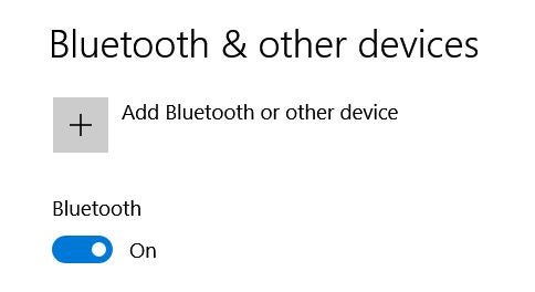
- Ensure that Bluetooth is ON in the "Bluetooth &other devices" window (photo 2).
- Left-click "Add Bluetooth or other device".
Step 3
- Left-click "Bluetooth" in the "Add a device" window (photo 3).
Step 4
- Left-click "HC-06" from the window that appears (photo 4).
Step 5
- Enter "1234" (without the quotes) when asked for a password (photo 5) and a "paired" message will appear (photo 6).
Step 7
Check that the HC-06 appears in the list of paired devices lower down the page (photo 7).
Step8
- Exit the settings menu.
Step 6: Talking to Your Plotter

Communication with your plotter requires a software "Terminal".
A suitable gcode terminal is described in instructable https://www.instructables.com/id/CNC-Gcode-Sender/.
Step 1
- Download and install this software ... full instructions are included.
Step 2
- Click the top-left "Run" button.
- The LED on the HC-06 bluetooth module will stop flashing when a link is established.
- A menu similar to that in photo 1 will appear if you are using the plotter described in instructable https://www.instructables.com/id/CoreXY-CNC-Plotte...
Happy plotting ...
Click here to view my other instructables.


