

Introduction: 3D Printed Bevel Gears (MVMT 25)


Bevel gears change the angle of any rotary motion. They're basically spur gears that interface at a specified angle (usually 90º) so that the power source doesn't have to be in line with the output of the motion. They're used in everything from hand drills to automotive differentials.
This instructable will show you how to use a Fusion 360 template to make your own 3d-printable bevel gears of any size and ratio you want.
507 Mechanical Movements is an encyclopedia of common mechanisms from the 1860's that serves as a good reference for this kind of thing. This mechanism is bases on Movement 25, "Bevel-Gears".This is going to be along project, so if you've got a specific mechanism you'd like me to make, feel free to make a request in the comments!
I used the gears to make this handy desktop sign. It passive-aggressively tells my coworkers whether I'm willing to talk.
Step 1: Tools + Materials
- Fusion 360
- 3D Printer
I use a Prusa I3Mk3S for just about everything. It's the best bang for your buck, in my opinion- very well made, 3D printable replacement parts, accurate and reliable.
- 3D Print Filament
- I used Matte Fiber HTPLA from Proto-pasta for this project, but pretty much any filament will work. I like this stuff because the finish looks really good.
- I used Polymaker Polyflex for the rubber feet. This stuff is good for this application because it creates more friction on a desk top to keep the sign from sliding around.
- 608ZZ Skateboard Bearings: There are lots of types to choose from, but any cheap ones will do. Don't worry too much about "spin time" as you would with fidget spinner.
- M3 Screws + Nuts: You could use any screws and nuts around this size, but I find these work well for small 3D printed mechanical projects.
- 100 Point Chipboard: This is used for the three panels and the sign panel. You can cut it with a straight edge and a hobby knife.
Fusion 360 is free and it's awesome. I use it for everything I design and fabricate.
Student / Educator License (renew free every 3 years)
Hobbyist / Startup (renew free yearly)
Step 2: Parameters
NOTE: Before you go any further, keep in mind that there's a Bevel Gear Add-In for Windows. Follow this link to download it and you won't need to model your own gears! https://apps.autodesk.com/FUSION/en/Detail/Index?id=2791960362914790676&appLang=en&os=Win64
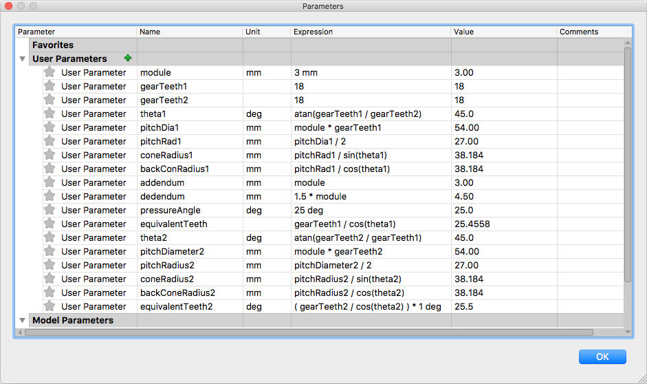
If you're on a Mac, follow the instructions here to model your own bevel gears. First, you'll need to have all of the parameters shown above entered in the User Parameters list. If you upload the Bevel Gear Template.f3d archive file attached here into a Fusion Project, all the parameters will be there for your use.
I'm not going to get into the math here, but suffice it to say that using all of these parameters will allow you to construct properly meshing bevel gears without much effort.
The parameters to pay attention to are gearTeeth1 and gearTeeth2. These set the number of teeth for each gear and allow you to create the ratio you need. For this project I made them both the same (18), but you could make them 18 and 24 for a 3:4 gear ratio, for example.
For small hobby projects, you probably won't need to mess with the other parameters to get a working result, but if you're savvy with gear design you can adjust the other parameters in Modify>Change Parameters.
Attachments

Step 3: Make Gear 1


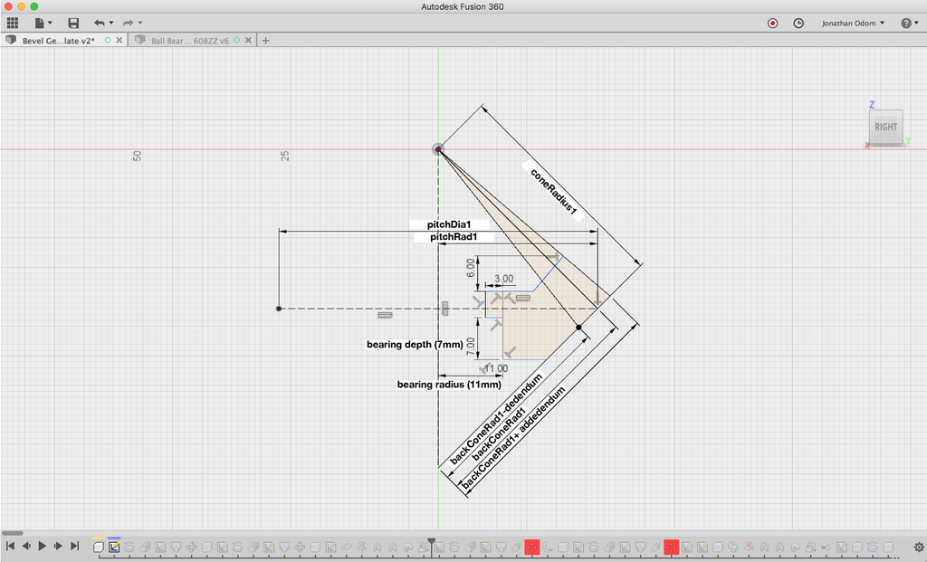
First, create a sketch in the Right plane. This will be the profile of the gear or cross-section. Using the parameters listed above, draw the lines you see there with the parameters on the annotated screenshot above.
Click on the pictures at the top of this step to zoom in if you're having a hard time reading the inline picture above.
You'll use the SKETCH > Sketch Dimension tool to enter the parameters. When you double click on a dimension, you can start typing the name of the parameter and it will come up in a list.
Scrub the video demo to 0:00 if you need a little help drawing these lines.
This particular gear is designed to press-fit a 608ZZ ball bearing, which is what the dimensions of the ledge on the middle of the profile are for.
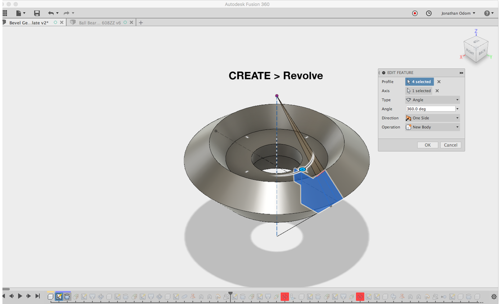
When the profile is finished, go to CREATE > Revolve to revolve the closed profiles that make up the cross-section. The Profile is the closed shape as shown above, and the axis is the first vertical line drawn in the sketch.
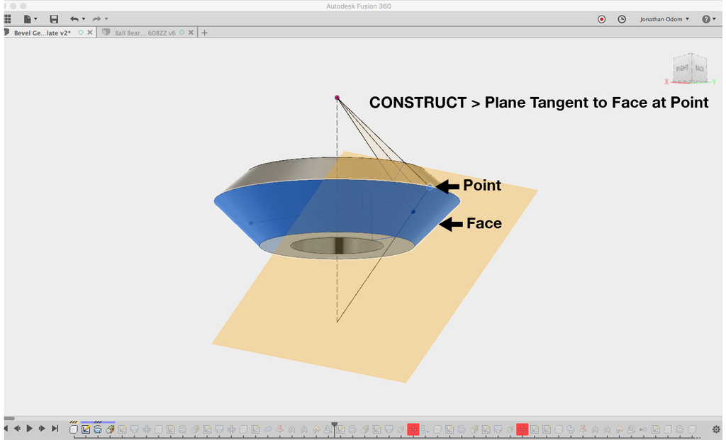
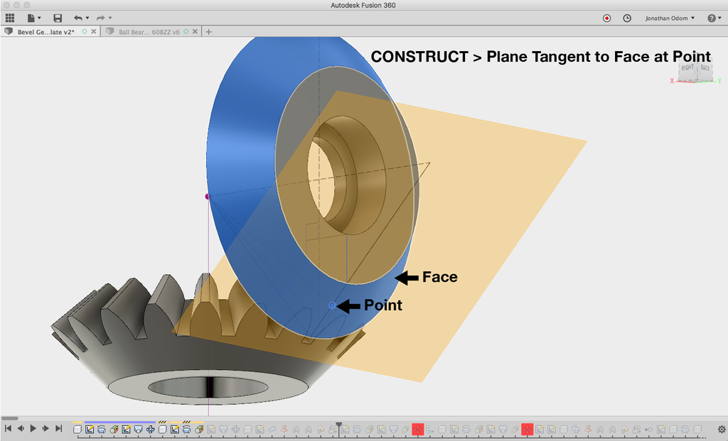
Next, you'll need to draw the tooth profile. To do this, show the first sketch in the Browser, then CONSTRUCT > Plane Tangent to Face. The Face is the underside of the gear shape, and the point is any point on the sketch that intersects with the Face.
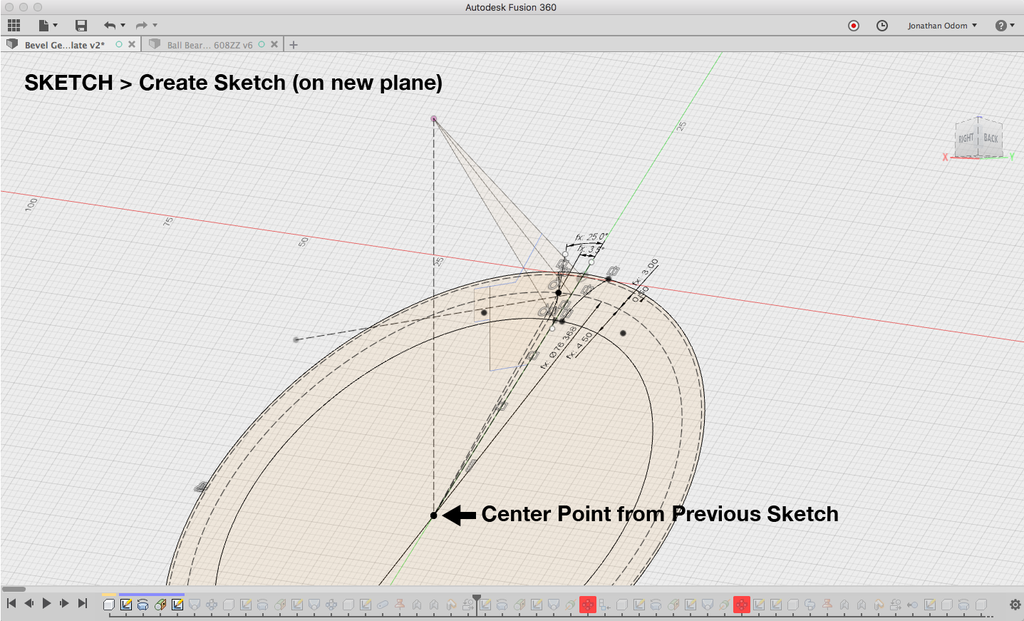
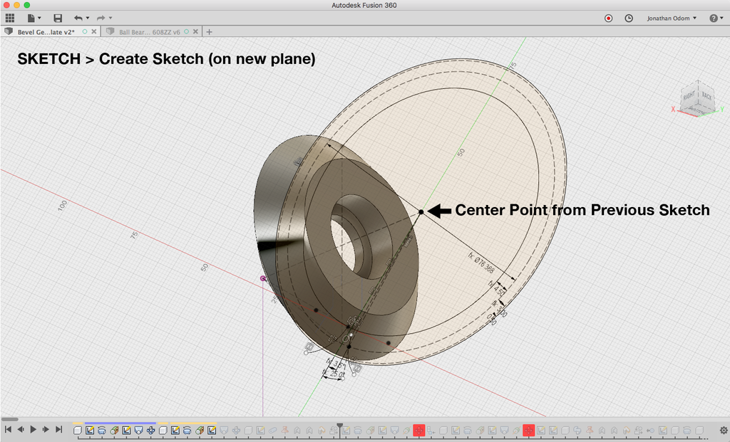
SKETCH > Create Sketch and select the plane you just made as the Sketch Plane. SKETCH > Project / Include > Project the lowest point on the vertical line from the previous sketch. This will serve as the center point of some concentric circles.
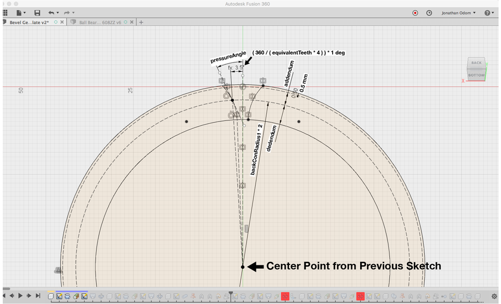
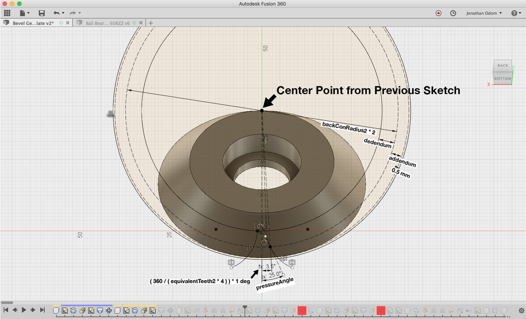
This sketch will be the profile of the tooth. Using the parameters listed above, draw the lines you see there with the parameters on the annotated screenshot/.
Click on the pictures at the top of this step to zoom in if you're having a hard time reading the inline picture above.
You'll use the SKETCH > Sketch Dimension tool to enter the parameters. When you double click on a dimension, you can start typing the name of the parameter and it will come up in a list.
Scrub the video demo to 3:53 if you need a little help drawing these lines.
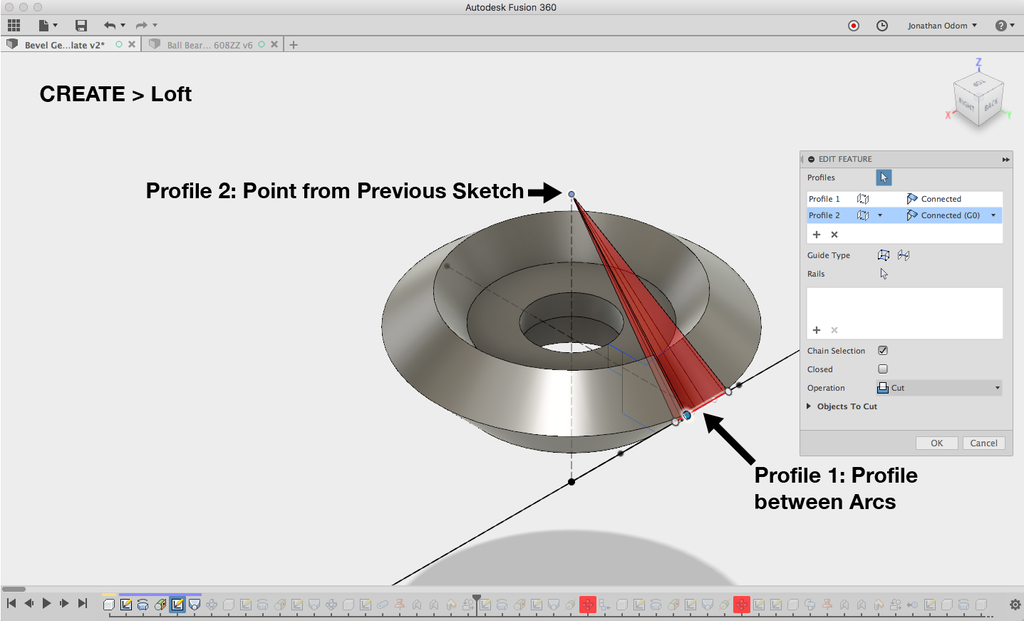
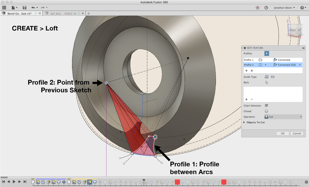
Now that you've got the tooth profile, you'll use CREATE > Loft to cut the shape out of the body of the gear. Profile 1 should be the closed profile from the most recent sketch, and Profile 2 will be the point at the top of the vertical line from the first sketch. This will cut out a tapered shape.

Now that you've got your tooth feature cut out, CREATE > Pattern > Circular Pattern to make all the teeth. Objects will be the 3 faces that make up the cutout, and Axis will be the cylindrical face in the center. Quantity is the parameter gearTeeth1.
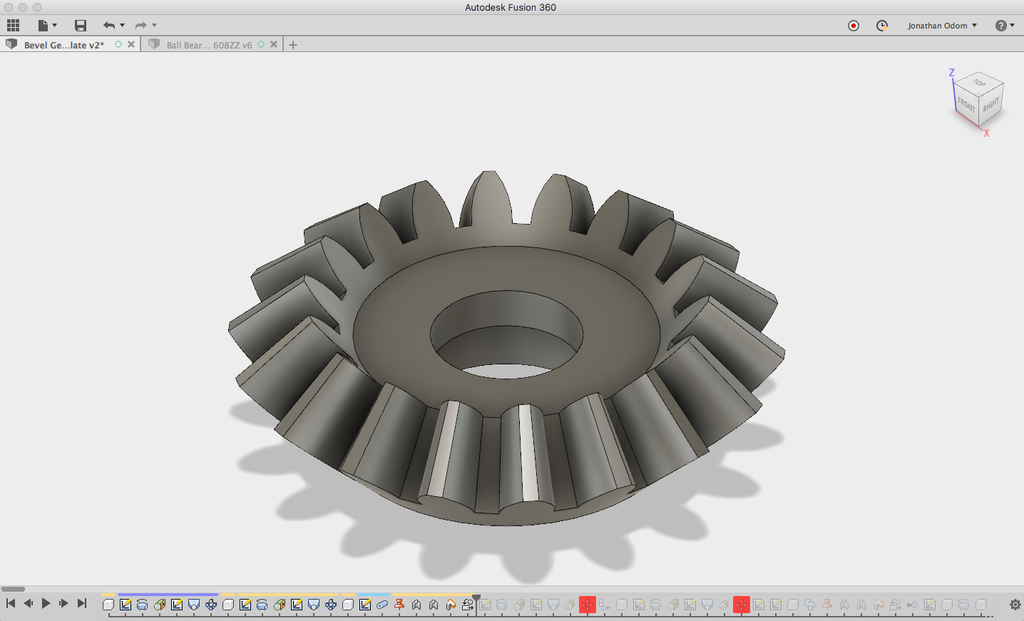
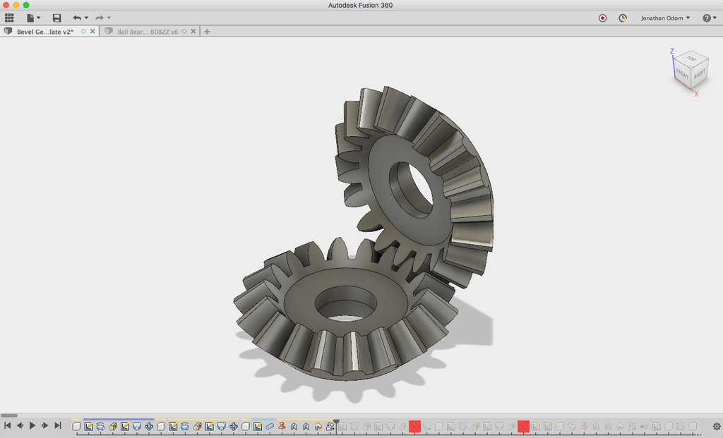
You should now have your first gear finished.
Step 4: Make Gear 2


Next, you'll need to draw the cross-section of the second gear.
First, create a sketch in the Right plane. SKETCH > Project / Include > Project the point at the top of the vertical line from the cross section of the first gear. This will be your starting point for the second gear, ensuring that it meshes properly.
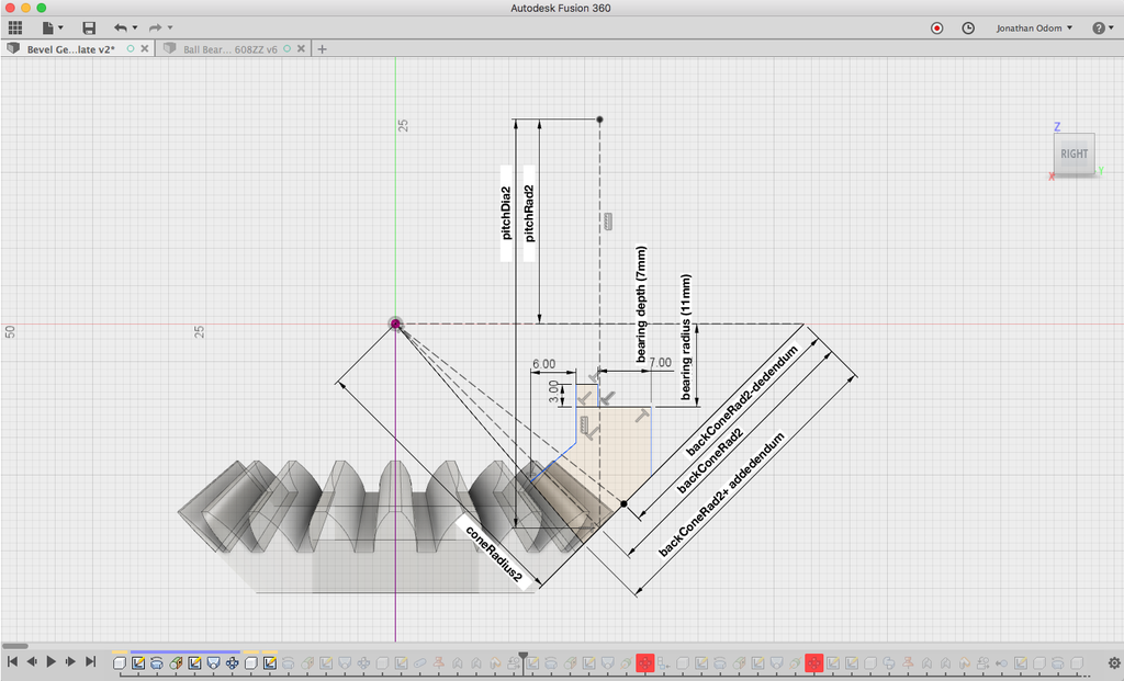
Using the parameters listed above, draw the lines you see there with the parameters on the annotated screenshot above.
Click on the pictures at the top of this step to zoom in if you're having a hard time reading the inline picture above. You'll use the SKETCH > Sketch Dimension tool to enter the parameters. When you double click on a dimension, you can start typing the name of the parameter and it will come up in a list.
Scrub the video demo to 7:24 if you need a little help drawing these lines.
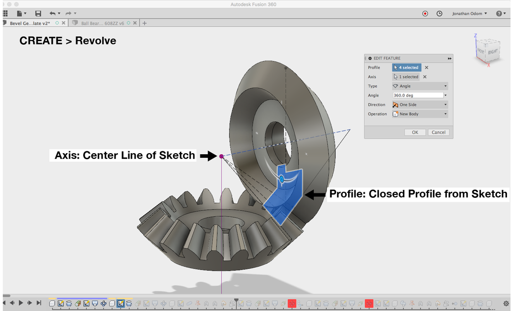
When the profile is finished, go to CREATE > Revolve to revolve the closed profiles that make up the cross-section. The Profile is the closed shape as shown above, and the axis is the first horizontal line drawn in the sketch.
Next, you'll need to draw the tooth profile. To do this, show the first sketch in the Browser, then CONSTRUCT > Plane Tangent to Face. The Face is the underside of the gear shape, and the point is any point on the sketch that intersects with the Face.
SKETCH > Create Sketch and select the plane you just made as the Sketch Plane. SKETCH > Project / Include > Project the point farthest to the right on the horizontal line from the previous sketch. This will serve as the center point of some concentric circles.
This sketch will be the profile of the tooth. Using the parameters listed above, draw the lines you see there with the parameters on the annotated screenshot.
Click on the pictures at the top of this step to zoom in if you're having a hard time reading the inline picture above.
You'll use the SKETCH > Sketch Dimension tool to enter the parameters. When you double click on a dimension, you can start typing the name of the parameter and it will come up in a list.
Scrub the video demo to 10:35 if you need a little help drawing these lines.
Now that you've got the tooth profile, you'll use CREATE > Loft to cut the shape out of the body of the gear. Profile 1 should be the closed profile from the most recent sketch, and Profile 2 will be the point on the far right of the horizontal line from the first sketch. This will cut out a tapered shape.
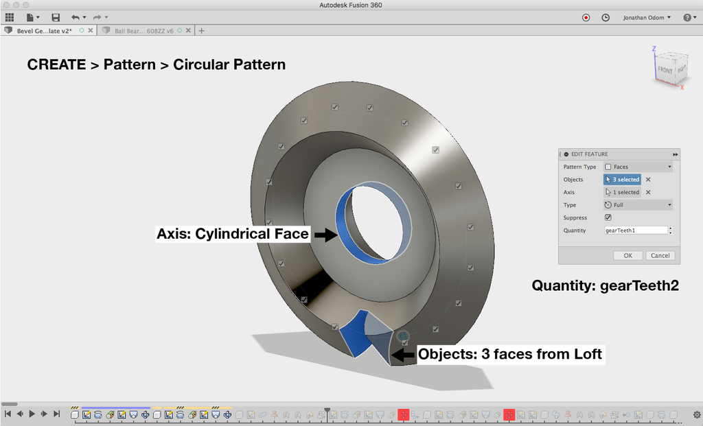
Now that you've got your tooth feature cut out, CREATE > Pattern > Circular Pattern to make all the teeth. Objects will be the 3 faces that make up the cutout, and Axis will be the cylindrical face in the center. Quantity is the parameter gearTeeth2.
Step 5: Create Joints
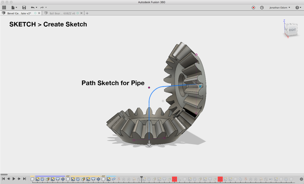
To make the gears move, you'll need a stationary component to join them to. For this example I just made a pipe from center point to center point of each gear.
SKETCH > Create Sketch on the plane you drew the first sketch on (Right), project the gears to give yourself some lines to work from, then draw the shape of a pipe from the mid points of the lines from the gears.
Scrub the video demo to 14:30 if you need a little help drawing these lines.
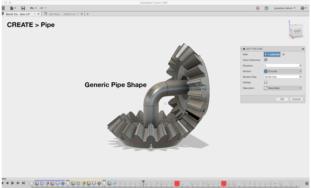
CREATE > Pipe, then select the path line from the previous sketch. The Section Size is arbitrary for the purposes of demonstrating the movement, but this pipe could be edited to press-fit the ball bearings.
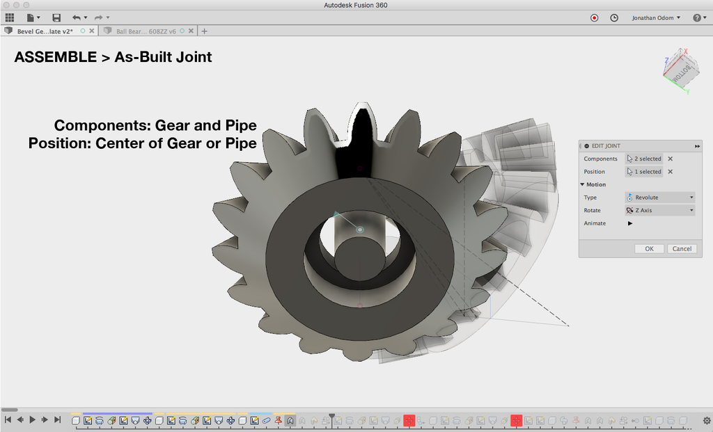
With the pipe component finished, right-click on it in the Browser and select Ground from the list. Go to ASSEMBLE > As-Built Joint and click one gear and the pipe. For Position, click one of the circular edges of the gear.
Repeat this step with the other gear.
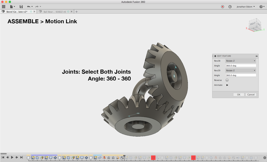
To see how it will move in real life, you can use a Motion Link. First, rotate one of the gears so that it meshes properly with the other one. Click on one of the joints, then set the angle to 360 / (number-of-teeth/2). Since there are an equal number of teeth and gaps (assuming the gear teeth parameter is an even number), that's the correct math.
ASSEMBLE > Motion Link, then click both of the joints. The default setting is 360º and 360º, which works in this case.
Right-click on a joint, then select Animate Model from the list and watch it spin!
Step 6: Application: Desk Sign

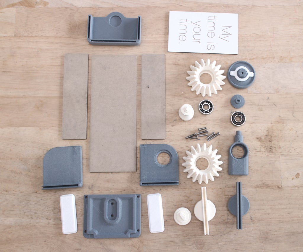
The STL files attached here are ready to print, the card stock can be cut using the PDF template attached. Be sure to print it at 100% scale / no scaling / original size.
My chip board was 2.6mm thick, so you might want to alter the design in Fusion to make the material match whatever card stock or chip board you might have available.
Here's a link to the file, feel free to download and remix it as you like: http://a360.co/2zU46UC
Attachments


Step 7: Vinyl Sticker


I used a custom vinyl sticker for my sign, but you could always just print something out on paper and rubber cement it to the panel if you don't have access to one. I just used it because I like the look of the letters being negatives showing the chip board behind it.
If you've got access to a vinyl cutter you can use the PDF attached in the previous step or you can just print it on paper.
- Take the cut vinyl sticker and remove the excess sticker material around the ones you want to apply.
- Take some vinyl transfer tape and smooth it down on top of the stickers.
- Flip it over and peel off the backing- do it slowly and carefully so that none of the letters peel off.
- Line up the panel with the edge of the sticker and press it down.
- Use a credit card or plastic putty knife to get rid of any bubbles and ensure a solid fit.
- Use a hobby knife or sculpting tool to remove the positives of the letters.
- Flip the board over and repeat.
Step 8: Assembl the Crank Axle


The best way to put it together is to assemble the crank axle first. There's a little "spring" that fits inside the knob that acts as a clip- there are divots in the bracket that catch points protruding from the spring. This lets the sign stay at the proper angle at 180º increments.
- Press-fit the spring as shown.
- Insert the knob in the bracket with the hole in it as shown, then press-fit the "knobShaft" into it through the hole.
- Use an M3 X 20 screw to lock them together.
- Press-fit "gearSide" into the "knobShaft". This may need to be adjusted so that the rotation puts the sign in the right place later. You can do this by holding the knob and turning the gear slightly.
- Press a 608ZZ bearing into the "post"
- Insert the "shaft" into the opening on "gearSide".
- Press the bearing on the "post" into the end of the "shaft" so that the shoulder is on the gear side.
- Press the "endCap" into the other end of the bearing.
Step 9: Finish the Base


- Fit the "bracket" and "post" to the base as shown, then use some M3 X 16 screws to lock them down.
- Screw the other bracket into place.
- Add the second bearing to the recess in "gearUp" and press-fit the bearing onto the post as shown.
- Press in the "clipDn" into the gear so that the notch lines up with the cavity in the gear.
- Hold the knob and turn the "gearSide" so that the "clipDn" is parallel to the front of the base.
Step 10: Add the Panels and Feet


- Add the panels to the base as shown. They should slot in snugly if the thickness is the same as the chipboard I used. If they're not snug, you could just glue them in place.
- Press the sign into to the "clipDn".
- Add the "clipUp" part to the top of the sign.
- Press-fit the "top" part so that it fits all of the vertical pieces and captures the round feature on top of "clipUp".
- Use some E-6000 or other adhesive to add the feet as shown.
Step 11: Finished Product


I'm pretty happy with how this turned out. The gears have really smooth action and the clip works well to keep the sign aligned.
It might be fun to do something like Thang's youtube video: https://www.youtube.com/watch?v=uCx9riKxTvY
What will you use bevel gears for? Show us what you make!


