

Introduction: Blue Robot Ant


Ants are amazing creatures. They need few resources and yet can do so much.
Many six-legged robots need up to three servos per single leg. That's a total of 18 servos that consume an enormous amount of energy. This conflicts with the ant's economy.
With only three servos (+1 gripper) and a little mechanics I realise a minimalistic robot ant. (114g + battery)
Basic knowledge in Arduino is required to make this project.
Blue Robot Ant
Supplies

3 (+1) servos SG90
ESP32-C3 XIAO or another ESP32 /ESP8266 (needs more space)
paperclip
little screws
5V buck converter MP1584
9V or 7.4LiPo battery
3D printer
All parts designed with Tinkercad and prepared with Ultimaker Cura.
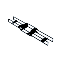


Step 1: Torso


Remove the tabs of all servos with pliers/saw and file.
Print the chassis and fix servo 2 with two pointy screws as seen in the picture. The center servo should be able to swing. It also gets a little cap where to fix a screw later.
Fix servo 1 and 3 and the cap for servo 2 with hot glue.
Before mounting the legs, the servos must be centred! To do this, use the small program centerlegs.ino to set the servos to 90.
Attachments

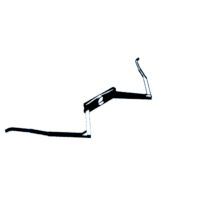
Step 2: Servos and Leg Parts


Each servo carries a leg pair, moving only a few degrees forward and backwards. Servo 1 and 3 move simultanously, so we could think about to use he same pin on the microcontroller for both.
Servo 2 moves in the opposite direction and should swing to bring the right traction of the legs to the ground. This swing is caused by servo 1 connected with a paperclip.
Print the legs and mount each to the servo. You may have to drill out the hole a little.
Step 3: Installing the Mechanics


Using screws and the paper clip, connect the mounting plate of the legs of servo 1 to the cap of servo 2. This should now tilt in rhythm with servo 1.
Step 4: Head and Gripper


The gripper is not really necessary, but it is a nice extra.
Insert the servo without arm into the frame. First set the servo to 90 ("centrelegs.ino" in Step2). Put the matching gripper part on the gear wheel and fix it with the servo screw. Then put the second part on the axis.
Glue the gripper upside down into the top of the head with hot glue and close the head. Put the head on the end of the torso and glue it.


Step 5: Battery Tail


The lower rear part is also attached to the torso and glued. It will hold the battery and the microcontroler.
Step 6: Electronic and Software


The 9V battery supplies enough energy for the servos, but the voltage must be reduced to 5V by the buck converter.
The power supply for the four servos runs in parallel via 5V, the data wires are connected to the ESP32. More connections are not necessary. Additionally, sensors or LEDs could be attached.
The software "Blue_Ant-RemoteXY.ino " must be transferred to the ESp32. You can find information about this on Getting Started with ESP32-C3
or
https://www.instructables.com/Getting-Started-With-ESP32-C3-XIAO/
The remote control of Step 7 is already included in the program.
Servo Library for ESP32-C3: https://github.com/songzhishuo/ESP32C3Servo
If you you use a ESP32 or a ESP8266 you have to change the libraries at
// ************************* Servos
/*
/ Blue Ant (2023) Markus Opitz
*/
// ************ RemoteXY *************
#define REMOTEXY_MODE__ESP32CORE_BLE
#include <BLEDevice.h>
#include <RemoteXY.h>

// RemoteXY connection settings
#define REMOTEXY_BLUETOOTH_NAME "ESP32-C3_Remote"

// RemoteXY configurate
#pragma pack(push, 1)
uint8_t RemoteXY_CONF[] =   // 43 bytes
  { 255,3,0,0,0,36,0,16,202,1,5,32,17,37,30,30,2,26,24,4,
  128,13,23,37,6,2,78,129,0,3,3,24,6,165,66,108,117,101,32,65,
  110,116,0 };
// this structure defines all the variables and events of your control interface
struct {

    // input variables
  int8_t joystick_1_x; // from -100 to 100
  int8_t joystick_1_y; // from -100 to 100
  int8_t slider_1; // =0..100 slider position
    // other variable
  uint8_t connect_flag;  // =1 if wire connected, else =0
} RemoteXY;
#pragma pack(pop)
// *************************

// ************************* Servos
#include <ESP32C3_Servo.h>   //for ESP32-C3
//#include <Servo.h>         //for ESP8266
//#include <ESP32Servo.h>    //for ESP32-Wroom
Servo servo1;  Servo servo2;  Servo servo3;  // Servo3 is attacheched to same pin as Servo1 !!!
Servo Jaws;
int pos1, pos2;    // variable to store the servo position
int centerpos = 90;
int minpos = centerpos-12;
int maxpos = centerpos+12;
int gripper;
//int speed1;


void setup() {
  Serial.begin(115200);
  servo1.attach(2); servo2.attach(3); servo3.attach(4);  //Servo3 can be attached to same pin as Servo1 //GPIOs on ESP32-C3!
  Jaws.attach(5);
  delay(2);
  servo1.write(centerpos);servo2.write(centerpos-7);servo3.write(centerpos);  //center all servos
  Jaws.write(centerpos);
 delay(3000);

 RemoteXY_Init ();
}


void loop() {
   RemoteXY_Handler ();

    if ((RemoteXY.joystick_1_x) < -30) {
      //Serial.println("<-- left   ");
      left(16);
    }
    if ((RemoteXY.joystick_1_x) > 30) {
      //Serial.println("  right -->");
      right(16);
    }
    if ((RemoteXY.joystick_1_y) < -30) {
      //Serial.println(" backwards ");
      // not yet installed
    }
    if ((RemoteXY.joystick_1_y) > 30) {
      //Serial.println(" ^forward^ ");
      forward(16);
    }
    gripper = map((RemoteXY.slider_1), 0, 100, 75,105);
    Jaws.write(gripper);
    delay(1);
}


void forward(int speed1) {       //speed1 in ms as delay between steps

  for (pos1 = minpos; pos1 <= maxpos; pos1 += 2) {
    pos2 = map(pos1, minpos, maxpos, maxpos, minpos);

    servo1.write(pos1);servo3.write(pos1);Serial.print(pos1);Serial.print("  ");  // front/rear legs
    servo2.write(pos2);  Serial.print(pos2); Serial.println("");                  // center legs
    delay(speed1);
  }

  for (pos1 = maxpos; pos1 >= minpos; pos1 -= 2) {
    pos2 = map(pos1, minpos, maxpos, maxpos, minpos);

    servo1.write(pos1);servo3.write(pos1);      // front/rear legs
    servo2.write(pos2);
    delay(speed1);
  }
}


void right(int speed1) {           //speed1 in ms as delay between steps

  for (pos1 = minpos; pos1 <= maxpos; pos1 += 2) {
    pos2 = map(pos1, minpos, maxpos, maxpos, minpos);

    servo1.write(pos1+10);servo3.write(pos1+10);  // front/rear legs
    servo2.write(pos2+10);                           // center legs
    delay(speed1);
  }

  for (pos1 = maxpos; pos1 >= minpos; pos1 -= 1) {
    pos2 = map(pos1, minpos, maxpos, maxpos, minpos);

    servo1.write(pos1+10);servo3.write(pos1+10);      // front/rear legs
    servo2.write(pos2+10);
    delay(speed1);
  }
}

void left(int speed1) {               //speed1 in ms as delay between steps

    //pos2 = maxpos + 1 -7; //-8 is to correct center position
  for (pos1 = minpos; pos1 <= maxpos; pos1 += 1) {
    pos2 = map(pos1, minpos, maxpos, maxpos, minpos);

    servo1.write(pos1-10);servo3.write(pos1-10);  // front/rear legs
    servo2.write(pos2-10);                           // center legs
    delay(speed1);
  }

  for (pos1 = maxpos; pos1 >= minpos; pos1 -= 2) {
    pos2 = map(pos1, minpos, maxpos, maxpos, minpos);

    servo1.write(pos1-10);servo3.write(pos1-10);      // front/rear legs
    servo2.write(pos2-10);
    delay(speed1);
  }
}
Attachments
Step 7: RemoteXY Control


The remote comtrol is already included in the code (see marked code lines).
At https://remotexy.com/ you could create your own interface for the smartphone remote control and insert it into the programme "Blue_Ant-RemoteXY.ino". You can find more information in this tutorial:
https://www.instructables.com/RemoteXY-Editor-How-to-Control-DC-Motor-With-Smart/
The app for the smartphone is available here:
https://play.google.com/store/apps/details?id=com.shevauto.remotexy.free
https://apps.apple.com/us/app/remotexy/id1168130280
Install the app on your smartphone, activate Bluetooth, open "RemoteXY", search for and pair with
"ESP32-C3_Remote".
Step 8: Run!

Switch on Ant, wait a moment, activate App.
RUN !

Judges Prize in the
Robotics Contest


