

Introduction: Bluetooth Clock


This is a nice little electronic project i got from Banggood. Its a very good test of soldering skills and if you have never done surface mount components then this will be a very challenging build. Or to put it another way this kit is not for beginners!
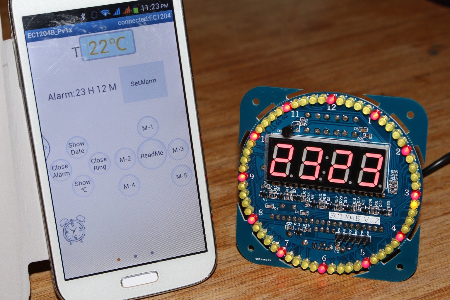
Once built the clock can connect to your phone via Bluetooth and will synchronize to you phone time and date, and also allow for changes to be made to the seconds display pattern and hourly reminder via the phone app. Also this clock has a temperature display and alarm.
If you want to buy this kit just search for "bluetooth clock" and you should find it. or the link for this kit is:-

Step 1: Surface Mount Components.


The first part and main part of this build is the surface mount components so if you have never soldered surface mount components then have a look at the video and it covers this part start to end!
Step 1) solder all surface mount components, resistors, capacitors and transistors.
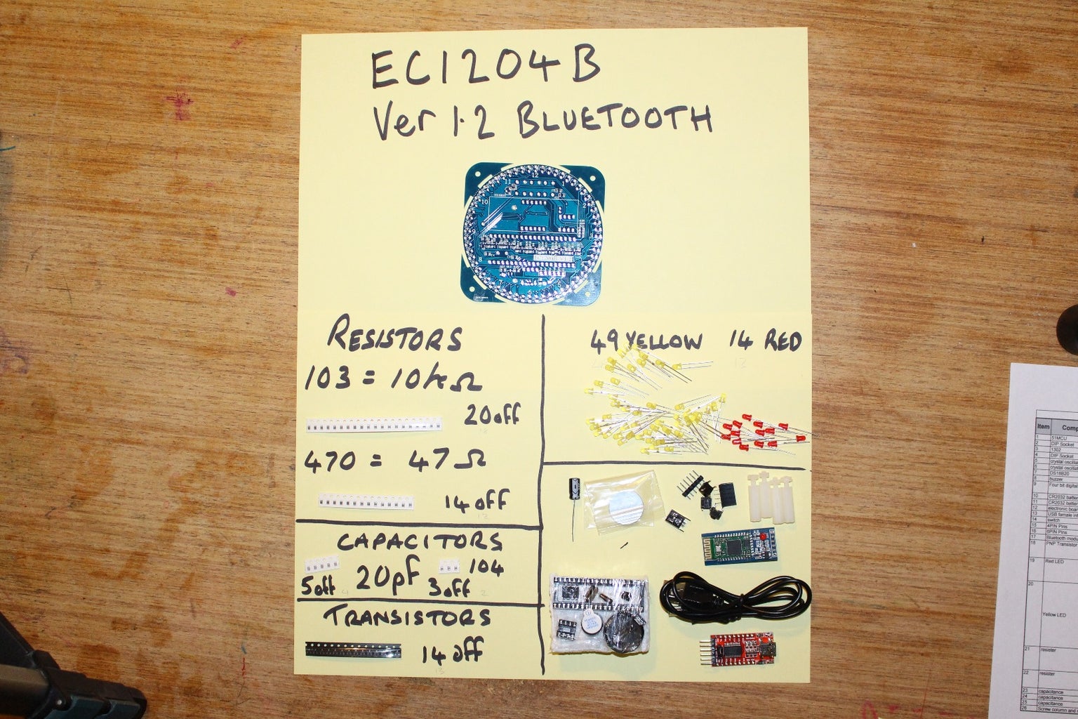
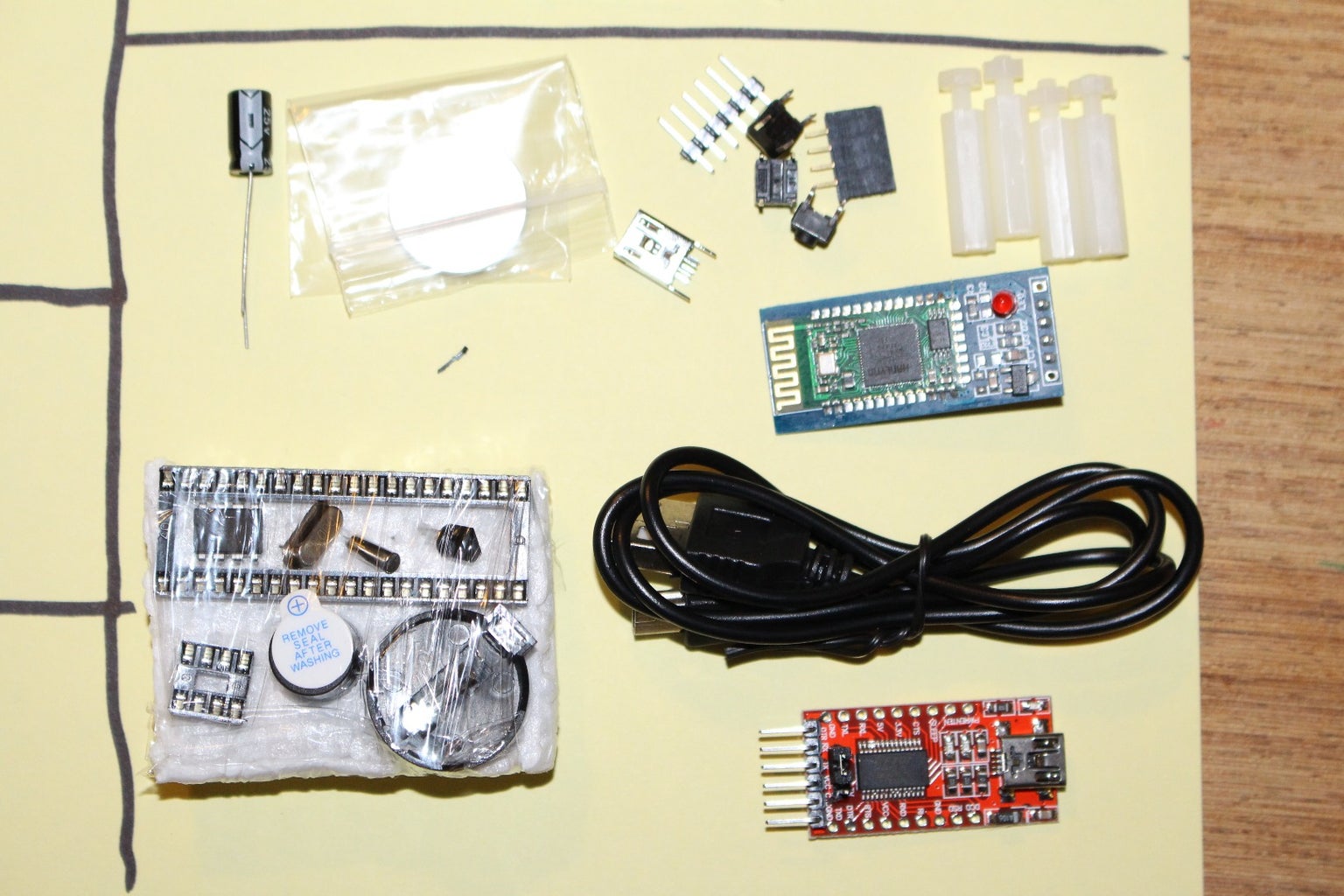
Before you rush into this build take a bit of time to work out what goes where, and download the component list. In one of the pictures you will see i have laid all the items out on a piece of paper, this was not just for the instructable but helps to identify the components. You should be able to see in the pictures that there are two different values of resistors and the actual values (47 ohms and 10000 ohms) are very different, so it is very import to follow the component list and make sure you get the right values in the right place. Also each transistor has two different resistors, so the values tend to alternate along the PCB. Try to place the resistors and solder with the numbers facing up, then if you have a problem you can check the values.
Try not to dwell to long on each component and if you don't get it right first time then let the component cool down before attempting again. You will need a very fine tip on your soldering iron and 0.7mm diameter solder. and whilst it might not be the best for the environment i prefer to use lead/tin solder.
But if you don't want to watch the video then this is the basic way in which i solder surface mount components.
- Carefully align the board so you can work in a nice line. Tape the PCB down to stop it moving.
- Start by carefully soldering one pad of each surface mount component.
- Then, one component at a time drop the item on the PCB and move into place with a toothpick.
- Whilst holding the component in place quickly remelt the solder and let it harden.
- If you are happy with the alignment then solder the other legs.
I haven't said anything about the capacitors, but you must be aware that there are two very different value. 4 capacitors are used to go either side of the crystals to form the oscillator circuit. these are marked as 20p which is 20 Pico Farads, two other capacitors are used for smoothing of the USB power input and the reset circuit these two are marked as 104 but this is a marking and not a actual value. 104 equates to a value of 0.1 uF (Micro Farad) which converted to Pico Farads is 100,000 Pico Farads (10 with 4 added zeros) Either way you look at it the two different capacitors look the same but are very different values. If you were to put a 104 where the 20p should go then i guess the crystal wont oscillate.
Step 2: LED's Crystals and Temp Sensor.


Step 2) Now we have done the hard bit the next bits of the build are easy! So i am following the instructions and the next step is to solder the two crystals. the smallest one should be mounted so it can be soldered down into place on the end of the can as shown in one of the photos. The 12Mhz is simple to do, but make sure it is flush to the board as the chip has to fit over top. It goes without saying that you should mount the components on the side which has the graphic on. You could mess up by mounting the crystal on the wrong side then you may find the display wont fit.
Step 3) 60 LED's, this is quick and easy to do but there are a couple of points to make, firstly you must make sure you get the correct color in the correct place! and that you position the LED's the correct way around. in the case of all the LED's the long leg should go towards the outside which means the flat on the body of the LED should be pointing in. Don't take too long soldering each LED as the heat can destroy the LED's
Step 4) Solder the temperature sensor into place, make sure you get it the correct way and don't solder it flush to the PCB, leave it slightly proud so the heat from the soldering iron doesn't damage it and it will detect a true temperature of the room and not just the temperature of the PCB!
Step 3: Buttons, Chip Holders Etc...


Step 5) solder the three buttons, two chip holders and battery holder. not much to say about these components apart from you should solder each component one leg first then check alignment before soldering the rest. The buttons can only go one way, and the two chip holders have a notch in the end which should be aligned with the graphic on the PCB, note the two chips face different ways! before you solder the battery holder bend over the leg which will end up under the display, else you will have to trim it down.
Step 6) The instructions say to trim the legs of the 8 DIL chip holder but i found that NOT to be necessary.
Step 7) Next to mount is the 4 * 7 segment display, this must be fitted with the decimal points at the bottom of the PCB (opposite side to the temperature sensor). Again i soldered only one leg then checked alignment before i soldered the rest.
Step 8) Solder into place the two headers. The 6 pin header for programming is mounted on the front and the 4 pin for the Bluetooth is mounted on the back.
Step 9) Solder the buzzer and big capacitor into place, however you must take care to get them aligned the correct way around as both items are polarized. the negative leg of the capacitor is indicated on the body, and the positive leg of the buzzer is indicated on the sticker. And lastly mount the USB socket, which can only really go one way around.
Step 10) Is the last step in the instructions and is to mount both chips. Firstly you may have to carefully bend the pins in to get them to fit in the holders and secondly you must make sure you mount the chips the correct way around. they both point in different directions so take care.
And lastly if you are fitting the Bluetooth unit slot that into place so it is over the 40 pin chip.
Step 4: Testing and Connecting to Bluetooth Phone.


Providing all has gone OK, you should do one last check for shorts then if OK, connect the USB cable.
And the clock jumps into life??????
Hopefully everything should be OK, if you have nothing then i would suggest you disconnect the USB and check for short again.
I had missed a resistor and this had taken out one of the 7 segment displays. so its worth just looking at this fault as it may help you fault find. on the front of the PCB are 8 transistors and each transistor has 2 associated resistors. if 8 LED's in a row around the outside (seconds) are not working then the fault will be one of the 8 sets. If however one of the seven segment displays ins't working then the fault will lie on the back on the PCB where another 4 transistor and resistors deal with each section of the 7 seg display.
If you have a problem more than this, then you will need to look at the circuit diagram to try and work out what is wrong, test the supply voltages first just in case!
If all is working then have a go with the Bluetooth... if not fitted plug in the BT module and download the app and install on your android phone. I have added the APK file above but i am not sure if that will work?? let me know if it doesn't work and i will add a link.
Anyway if you have got the APP then it should be a simple task of pairing the device using the pass code 1234, and once this is done run the APP. press "connect ring" to connect to the phone and straight away the clock should sync to your phone. You then can play with the alarm, hourly reminder, and also the second pattern can be adjusted.


![Tim's Mechanical Spider Leg [LU9685-20CU]](https://content.instructables.com/FFB/5R4I/LVKZ6G6R/FFB5R4ILVKZ6G6R.png?auto=webp&crop=1.2%3A1&frame=1&width=306)


