

Introduction: Build a Powerful High Voltage Generator That's Also an Induction Heater! | Orange Plasma Arcs and Red-Hot Metal Heating | Inducer (How To)


In this project, I will show you how to build a powerful tool that can generate up to 90kV with high current, orange plasma. This can also be easily switched for an induction heater to use on metals.
For the best quality read, check out this article on my homepage here. If there's a pop-up, just simply click dismiss at the bottom. Also, don't forget to subscribe for free to support my work!:)
Step 1:
A Quick Preview
This is my “Inducer” project that I’ve been working on for the last few months and am very excited to finally be sharing it with you. It is a tool that is able to produce magnificent high-frequency sine waves, which when used with the principles of electromagnetic induction, can create dazzling high-voltage orange arcs or heat up metals until they become red hot.


Everything is the same between them except the casing and transformer/work coil. Same circuit and board!
Here’s a quick preview:
Step 2:
Pretty cool, right?

*The voltage will arc through the air such as seen here at 3kV/mm for smooth area surfaces and 1kV/mm for wire tips.
This works by using a super neat circuit called a ZVS, or Zero Voltage Switching circuit to continually power up an LC oscillator setup (more on that later) at set intervals for maximum power transfer. In addition, since it only switches at zero volts as the name suggests, it has very small switching losses that make it super efficient and heat up much slower than other high-power oscillator designs.

*Unlike this knife haha.
Exacto/utility knives are great for an induction heater since they’re only 0.5mm thick, making them get red-hot super fast. Also good for precision cutting!
As well as this project’s awesome ZVS circuit capabilities, I’ve also added seven gorgeous high-power RGB (multicolor) LEDs with a built-in logic circuit for custom colors. This is complete with battery charging and monitoring, which makes for easy charging and programming. I feel this just adds to the Inducer’s awesomeness.

*In the spirit of December (which it is at the time of writing this) I made the top three RGB LEDs look like Xmas lights! In addition, there are three more powerful RGB lights under the fan which are constantly changing color. Pretty cool!
In addition to this, the Inducer has a built-in BLDC fan with knob-based speed control to find the perfect balance between noise and efficiency, leading to quick cooling across the high-power MOSFETs. This gives it a longer use time which is especially helpful in induction heating. This also surprisingly works as an awesome fume extractor, though, I recommend using a filter to protect the PCB over long durations. It shoots all the fumes out the side away from your face!

Since I thought a digital display might muddy up the design, I decided to use the color of one of the onboard RGB LEDs to represent the charge left in the logic circuit’s battery.

Blue = ~75% charge
This is pretty cool since it means that when the battery is full the LED will be purple, then it’ll drop down the visible electromagnetic spectrum until the LED is red, representing the battery is empty. This also means only you or anyone else who happens to be reading this will know how much battery is remaining, so take satisfaction in that haha.
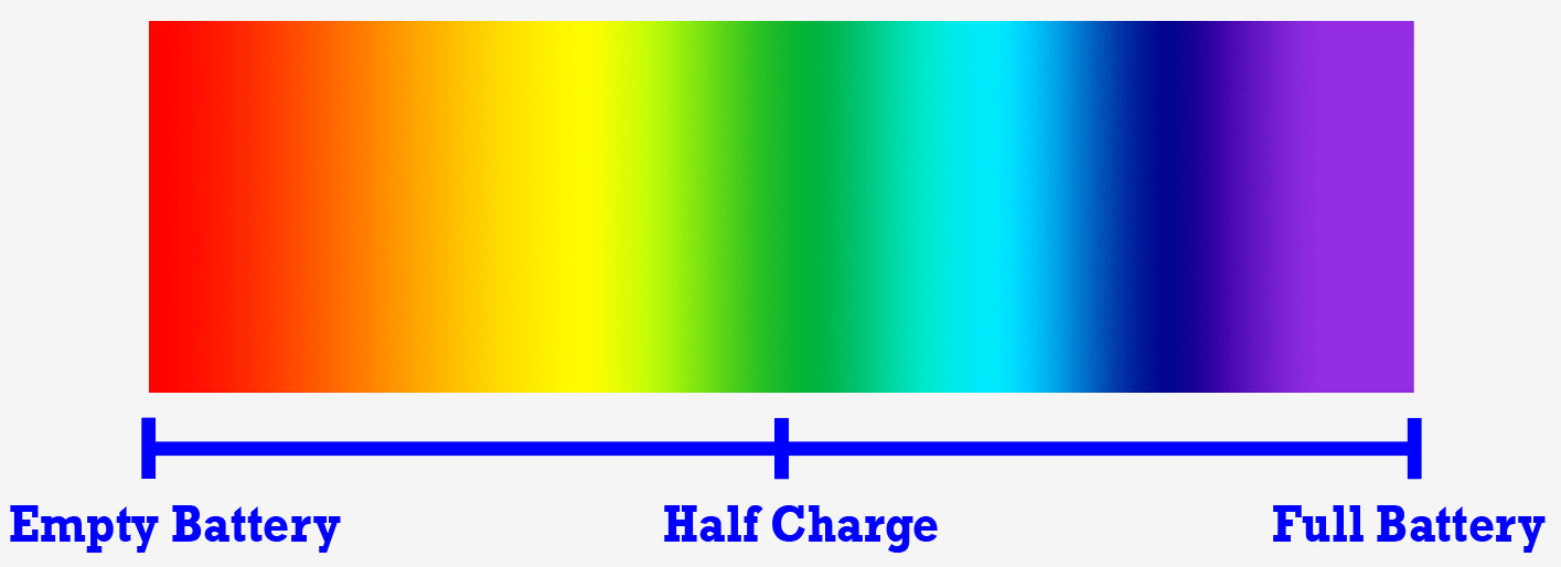
*Fun fact: The human eye is most sensitive to yellow-green light, around 555nm in wavelength. That’s why this color appears as the brightest to us.
Looking for a specific section? Jump to it using these links:
Understanding the Hardware | The Magic of Oscillations | Building the Board | Safety | Assembly | Programming | BOM (Bill of Materials)
Working Concept
As I explained above, the main idea here is the application of the ZVS circuit in producing beautiful high-voltage/high-frequency sine waves.

*The different colors on the voltage graph represent the different voltages on each side/half of the ZVS circuit.
We are able to use these sine waves for numerous applications following the ideas of electromagnetic induction explained in Faraday’s Laws. These laws basically just state that:
- As electricity flows through a conductor, a magnetic field forms around that conductor.
- If the amount of electricity flowing through that conductor is changing (AC), the magnetic field around that conductor will also be changing.
- And most importantly, if a conductor is near a changing magnetic field, an AC current will be induced into that conductor.
In reality, it’s a bit more complicated than this such as the effects of the distance between conductors (expressed through inverse square law), relative permeability, and other things, but that was the main idea.
In high-voltage generators, we are able to use this concept of electromagnetic induction to create huge voltages by varying the number of turns of wire from one coil to the other. If we then pass AC through one, it’ll induce electricity from one to the other. The new voltage will be proportional to the ratio of turns of wire between them.

In induction heaters, we are able to use the idea of induction to induce electricity directly into metals or other conductors. This creates heat, as everything has an internal resistance. If you’ve ever passed a large current through a thin wire, the instant incineration/burning of the wire should be all that’s needed to prove my point here.

Let’s dive a bit deeper into how exactly a ZVS circuit is able to pull off creating these fascinating and useful oscillations, and how you can build your very own Inducer (in two different flavors)!


Understanding The Hardware
This circuit can seem a bit complicated, it certainly took me a few tries to understand it, so stay with me.
Here is our basic ZVS circuit (I’ll dive into how everything else works later):

First, let’s break down the components. Q1 and Q2 are N-channel MOSFETs or Metal Oxide Semiconductor Field-Effect Transistors, which are basically just switches that are able to do two things: switch fast and allow current far larger than what is supplied to it at the gate (G) to flow from the drain (D) to the source (S).

The neat thing about MOSFETs is that the voltage allowed to flow from drain to source is dependent on the voltage applied at the gate. So long as the voltage is above the threshold voltage (in the datasheet), the voltage you apply to the gate determines its conductivity. In short: the more you raise the gate voltage, the better the MOSFET conducts. The keyword here is voltage, because this means that you can use a low amount of current to control a huge amount of power. You can just imagine it as the beefy cousin of the regular NPN transistor.

Note: Though it’s the voltage that determines the conductivity of an FET, current greatly affects the speed at which the MOSFET is able to turn on and off. If you want to turn a FET on and off really fast, you’ll want to be able to supply larger currents.
The other component you may not be super familiar with is the Zener diodes I have placed across the gate of the MOSFETs. All you really need to know about them for now is that they break down voltages above their rating (12V) so that there is never more than 12V supplied to the gate which could damage the FET. This isn’t super necessary since the LiPo only supplies 12V, however, sometimes in oscillator circuits a higher voltage can become present and they’re there just as a precaution in case it does. For example, I’ve noticed voltages spikes up to 30V upon power up. (This could be fixed using a soft start circuit but that’s for another time.)
Now let’s move on to the actual workings of the circuit. I placed the schematic again above so it’s easier to reference as I explain it.
- First, current rushes from the lower LiPoVCC into the gates of the two MOSFETs. (The resistors R21 and R22 are there to protect the gates of the FETs in addition to isolating the diodes D17 and D18 from each other.) As current flows, slight variations in the distance and other factors cause one FET to turn on before the other. For the sake of example, let’s say Q1 turns on first.
- As Q1 turns on, current is allowed to flow from the higher LiPoVCC, through the inductors (which act as a choke to protect the power supply), through the drain and source of the MOSFET to ground.
- Since the diode D17 is connected to what is now flowing to the ground, it is also grounded and since that diode is connected to the gate of Q2, it means that the gate of Q2 is grounded which turns Q2 completely off.
- As the current flows, the capacitors C19-21 charge up and a current begins to flow across the inductors. This flow is an LC oscillation (LC standing for (L) inductor - (C) capacitor), as the energy in the electric field of the capacitors charges up the magnetic field in the inductor, which then collapses back into the electric field of the capacitors.
- This setup is called an LC oscillator. In a perfect world, they would continue to charge and discharge each other creating a nice infinite sine wave. However, due to thermal and resistive losses in reality, the sine wave dampens a little each time and eventually runs out of energy. This ZVS circuit is special because right after the first, strongest wave created by the LC oscillation begins to fall, a fresh bit of power is applied to keep it going without dampening out over time. Here’s how that happens:
- As the magnetic field of the inductor collapses, the energy stored in the capacitors causes the current to continue flowing, and the inductor generates a voltage across itself that is opposite in polarity to the supply voltage (this is due to Lenz Law). This negative voltage is applied to the drain of Q2, which in turn forward biases’ diode D18.
- When D18 conducts, the negative voltage is applied to the gate of Q1. This turns the FET off. (Notice this is at 0V (well… technically around -700mV), which means the MOSFET switching losses are minimal.) With Q1 off, Q2 starts conducting and the cycle repeats.
Pretty neat, right? The circuit was originally ideated by Vladimiro Mazzilli around 15 years ago which is pretty cool considering how recent it is in the grand scheme of electronics. This circuit is not for the faint of heart.

*Microwave ovens also use an LC oscillator setup (but a bunch of them put together) to create insanely high-frequency microwave radiation at 2.45GHz, which is the resonant frequency of water molecules.
With that out of the way, let’s check out the rest of the circuit.
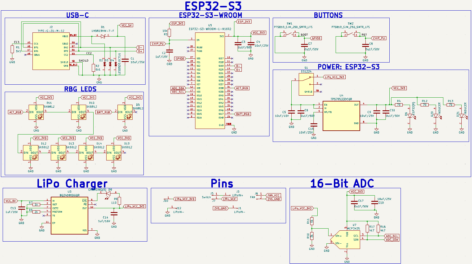

*For a higher-quality image, I recommend downloading/opening the photos in a separate tap.
Don’t be intimidated, the hard part was the ZVS circuit. The rest is just connecting up all the ICs (integrated circuits) so that they can talk to each other and perform their designated tasks. Let me explain.

*SOC - System-on-a-Chip
After days of experimentation, to make this circuit work I found it best to completely isolate the high and low power sections (the ZVS and RGB logic). I originally just wanted to have one built-in 3S charger for the main 3S LiPo, then use that to power the logic and RGB LEDs in addition to the ZVS circuit. Theoretically, this can be done as 12V isn’t that high. However, due to the unique nature of the high-power oscillator, I ran into problems (mostly involving me frying the ESP32-S3 again and again). I was able to make it work for a little while but it lacked consistency. By isolating the two, you lose the perk of being able to charge/monitor the main battery but it furthers the lifespan of the Inducer significantly. In the end, I believe this is a better trade-off.

*Early prototyping failures.
Now, let’s get to it. Everything in the ESP32-S3 box is for our ESP32-S3 microcontroller. Basically, we just have some buttons for resetting the controller if we need to, a low-dropout-voltage regulator to bring the voltage down to 3V3 from 3V7 (from the one-call LiPo), a USB-C port, and our RGB LEDs. If you want to learn more, check out this page which has all of the datasheets for the ESP32-S3.

To charge the one-cell LiPo battery that powers our logic circuit, we’ll need a LiPo charger circuit. I built this around the BQ24090DGQR IC, which I’ve used in previous projects. To learn more about why I placed everything the way I did, check out the part datasheet. I get most of my information from there.

In case you’re wondering, this is how the 3S LiPo that powers our ZVS is wired. Turns out it’s not so much one big battery but rather three regular one-cell LiPos wired together in series. In my first design, I tried to make a 3S LiPo charger based on the idea of charging each cell individually through the balancer with the same IC as above. It should work, right? Not really. Though it could charge each cell individually, due to the increased voltage that arises each time you connect one in series, you would have to connect it the same for the charger ICs. This would either require three separate grounds or a transformer. No thanks! I’m happy with the cheap charger I got from Amazon.

To monitor the one-cell LiPo we are using to power our logic, I chose a 16-bit resolution ADC (Analog to Digital Converter) chip. (If you’re interested, I talked about ADCs in this project.) Even though the ESP32-S3 has a built-in ADC, it only has a 12-bit resolution, meaning it can only represent a possible 4095 different values while our new 16-bit one can represent a possible 65535 different values. That’s 16 times the resolution of our ESP32-S3! This is especially useful because we are only reading a small range of voltage values to determine the charge in the battery, meaning we need a high resolution to be able to read that range accurately.
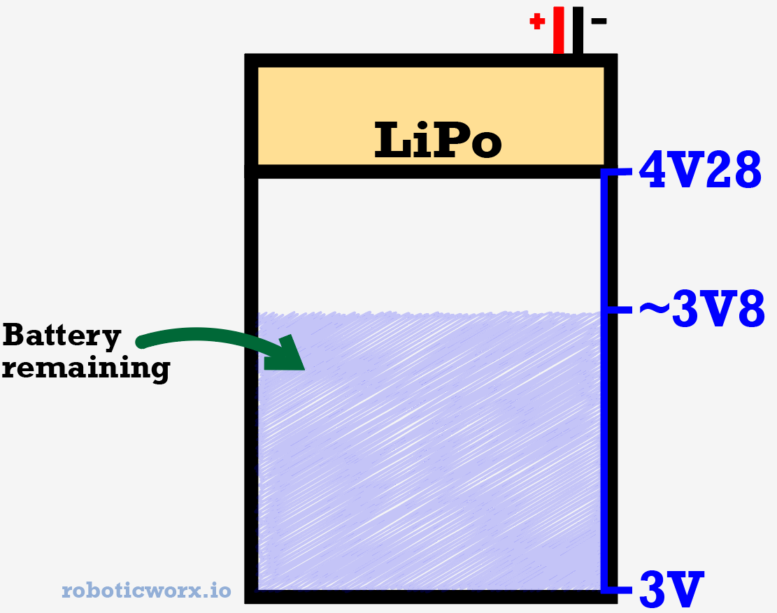
This IC communicates with our microcontroller over I2C. The resistors and capacitors I chose for this IC, like the last one, were also recommended by the part datasheet. However, I did choose the resistor values on the left since it’s a voltage divider configuration to drop the LiPo voltage into a safe range for the IC. (It measured best with 2V and below.) You can learn more about how I chose them here.

The last bit of our circuit is the step-up module, which just boosts the voltage of the fan to make it spin faster. I modified mine to use an external potentiometer, which essentially turns it into a kind of speed controller. I’ll go into how I did that in the assembly section. You could technically build your own for this, but I’d probably recommend just buying the module off Amazon.

I labeled the smaller components NC because it is purely for display and we are not building this circuit on the PCB.

That’s all as far as the circuitry goes! Thanks for sticking with me.
The Magic of Oscillations
Something interesting I noticed when first testing out some different oscillator ideas that I didn’t know before, was the effects that frequency had on electrical resistance. Turns out, there’s a lot more that goes into oscillators than one may think, so hopefully I can shed some light on it.

The “magic” of oscillations. Get it? 😂
When I first started prototyping ideas, my first was just to simply turn a MOSFET on and off really fast while connected to a load such as an electromagnet. Theoretically, as I increased frequency, induction should increase too. That’s what the formulas say, right? Not so much, the electromagnet never had any power running through it. Why? Turns out, there are a lot of problems that come with increasing frequency.
XL = inductive reactance, f = frequency, L = inductance.
One of which is known as inductive reactance, which is just a fancy way of saying AC resistance. Basically, what happens is as frequency increases, so does inductive reactance which is very bad when shorting over a load such as some pure copper coil, as Ohm’s law states V = IR. If resistance increases even by just the slightest bit (say just one ohm) in a circuit with very little resistance (the coil was around 0.7 ohms total), it will essentially cut the amount of current it could draw in half. However, in my case, it was a few hundred ohms which meant that the electromagnet had only a couple tens of milliamps running through it. That’s nothing!
I was able to find this was the problem through a little experiment: An experiment involving a permanent magnet and coil of wire.
I connected my electromagnet to a gate driver and ran it next to a permanent magnet at 3KHz:
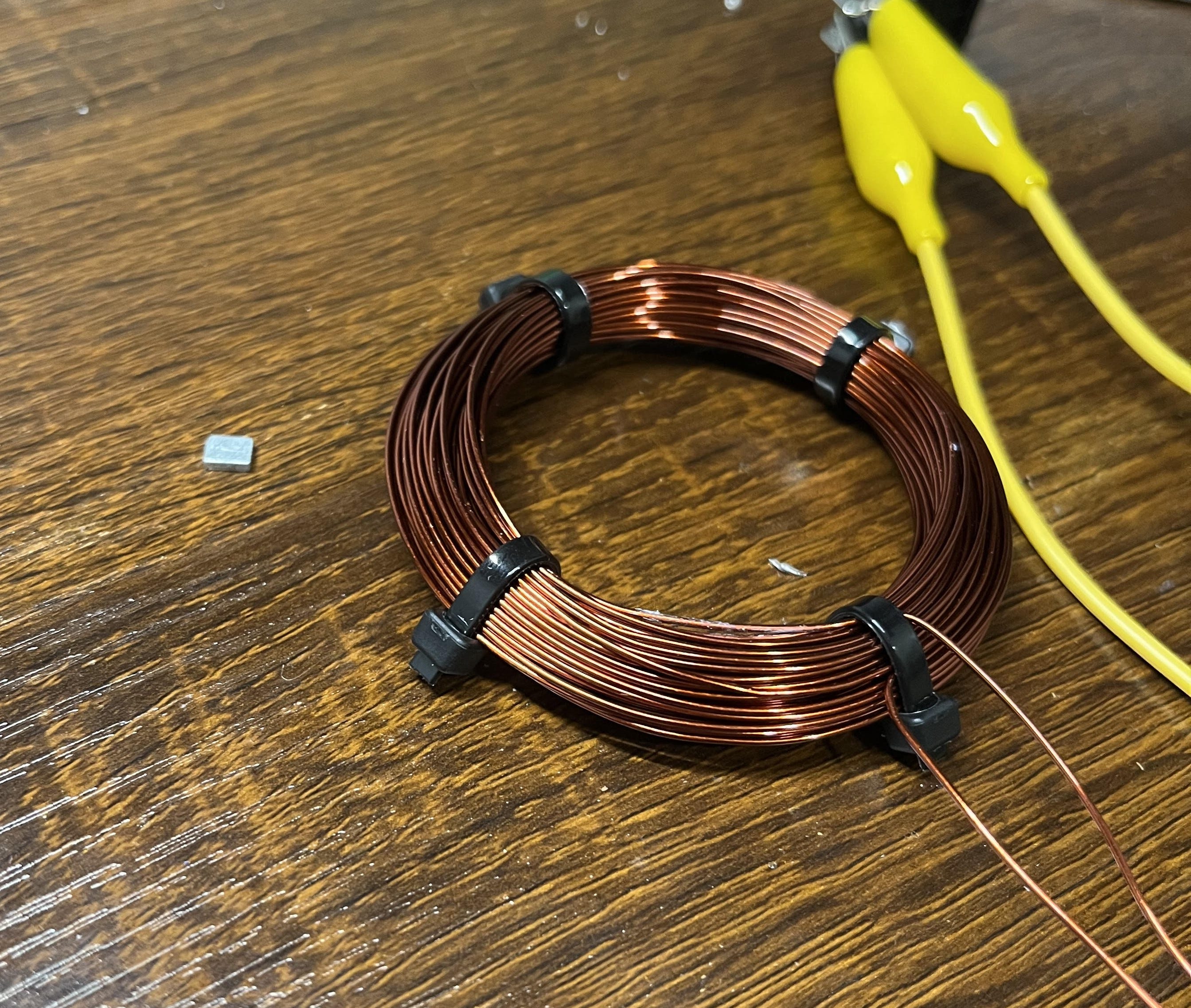
It didn’t budge. Then, with the magnet in the exact same position, untouched from the previous photo, I changed the PWM signal of the gate driver to 1.5KHz instead.

The smaller inductive reactance yielded from a slower frequency, (smaller resistance in the coil), was able to produce a higher current flow via Ohm’s law to generate a larger magnetic field around the coil. This was strong enough to attract the magnet. Through some more research, I found that this was also due to something known as the Skin Effect, which states that electricity prefers to travel along the outside of conductors at higher frequency. This decreases the area in which electricity can travel, which increases resistance.

Another issue was that the different turns of wire were coupling to each other, also increasing resistance. This could mostly be fixed by spreading out the turns of wire, which is ironic as more turns normally means a stronger magnetic field (most of the time).


Here, the wires are spaced out more. Everything else is the same!
At lower frequencies though, this setup actually worked pretty well! Here’s a funny thing I made by changing the frequency to 10Hz. Every 100ms, the magnet attracts the permanent magnet. Every other 100ms, it’s off so the magnet falls due to gravity. This makes for a funny bouncing 😂. Maybe I’ll do a project using something like this another time, but for now, it’s just not quite powerful enough for the induction applications I have planned.

Another problem in this design was that I was losing a lot of energy due to switching losses in the MOSFET, which also explains why all my FETs got super-hot and I burned out like twenty of them. In addition to that, I was producing a square wave which isn’t as effective in transferring power (since the FET was only ever on or off).

I needed a nice sine wave that only operated around a few tens of kilohertz to avoid switching losses, have more effective power transfer, and smaller skin effect/coupling. Enter the ZVS circuit!

With decent electromagnetic induction finally in play, I decided to name it the

or just

for short to recognize the circuit’s accomplishments.
Here’s one of my first ZVS circuit prototypes in which I got a really cool arc to dance around on an old/broken circuit board from a previous project.

Building the Board
With the theory down, let’s build this thing! Really, our PCB only needs the ZVS circuit, but as you know, I added a few extra parts to make it a bit more awesome.
Here’s what the final layout looks like:
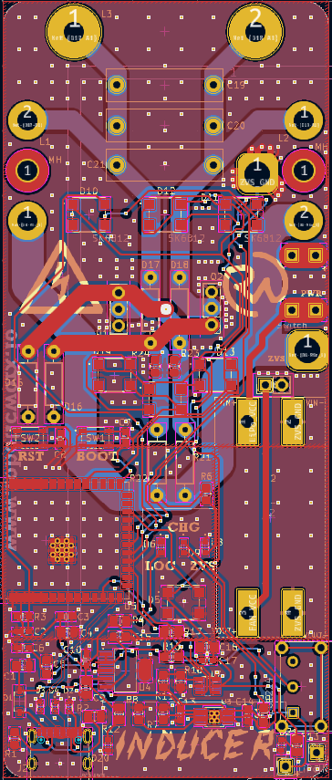

- The Gerber/fabrication file for the board, editable KiCad files, and part list for all the components required in this circuit can be found here on my GitHub.
- As always, I know that it can seem like a pain to have to order parts but it’s really not so bad as almost all the parts you order from one project get reused. Think about how much you’ll learn with some hands-on experience!
- It’s important to note that the PCB is the exact same for both the high-voltage generator and the induction heater, the only difference is the CAD files. So don’t worry about if you’re building the right board, as there’s only one. I’ll go into more detail in the Assembly section.
If you’re interested in learning more about PCB layouts and routing, check out Robert Feranec and Phil’s Lab on YouTube. They’re great designers and I’ve learned a lot from them.
Let’s build the board. To get it made, we will have to go through a PCB manufacturer and as always, I chose PCBWay!

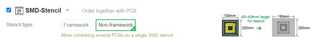
As usual, it was super easy and streamlined to get my custom boards ordered. I didn’t even have to leave my ECAD software since they have so many neat plug-ins such as mine for KiCad. They even have a super awesome Christmas event going on right now, where I was able to score a free stencil squeegee.
However, you can always just order through their website by going to PCBWay.com, clicking on quick-order PCB, and uploading the Gerber/Fab file for the board. Or alternatively, just go here which I have saved in my favorites bar. I recommend clicking the stencil option at checkout to save some headaches!

Of course, the boards were as awesome as ever when they arrived a few days later.

The reference/placement sheet for the PCB components can also be found on my GitHub. Remember, just ignore anything with “(NC)” next to it, that was for demonstration purposes.
Here’s a short video outlining the board assembly process:
Step 3:
Beautiful…
NOTE: Before uploading any code, you must put the board into bootloader mode. You can do this by holding the boot button > hitting the reset button (RST) while it’s held > and then releasing the boot button. In addition, if the board ever has power but is not on (the RGB lights are off), clicking the RST button should resolve it. There is a hole in the 3D-printed casing where you can reach it after assembly.
As you may have noticed in the PCB assembly video, I recently got my hands on some super awesome new gadgets that have made building all my projects much easier. As you just saw, I now have some super cool ESD (electrostatic discharge) tools like my new ESD table mat and tweezers which makes handling all my tiny and fragile ICs much safer. In addition to that, I also have the all-new Soldered Inkplate 6 which is a super neat ESP32-based board that works like a huge black-and-white high-resolution display. I’m sure you’ll be seeing this get some awesome use in a future project. These items and more would be due to the kindness of the people at Soldered Electronics! They have a huge variety of kits and components to help teach you about the amazing world of electronics. In addition, they allow you to purchase singular components which is awesome since most companies make you buy them in packs (which is more expensive).


I really appreciate Soldered Electronics for helping support my work and definitely recommend you check them out when building your next project. They have some really cool products and I’m sure you’ll feel like a kid in a candy store when browsing through their site. :)
Something else special I would like to point out about this board is the exposed traces on the back.

This circuit requires a lot of current, so much so, that on normal PCB traces they would burn up and break. The exposed traces help avoid this by providing you with some space to apply solder directly to the board, which helps with thermal relief. Similar to how thicker wires are able to handle larger currents. This being said, they are still exposed traces. Do not touch them!
I feel like this is a pretty good segue into my next section.
Safety
Yes, this project is super cool (at least I think so) but it’s also super dangerous. Just watch what it can do to this calculator.
Step 4:
Just imagine what it would do to the fragile insides of your body.
This being said, please only build this project if you know you can do it safely. I am not responsible if you hurt yourself or anyone else!High voltage combined with high current can be extremely dangerous and even lethal. If you plan on only building the induction heater version of this project, good: it’s much safer, but you should still use general safety precautions to protect yourself. Here are a few tips:
- (Both) Never bring any part of yourself close to any terminal of the device.
- High voltage can arc to you from a distance. Always be vigilant!
- (High voltage) Use a chicken stick (insulated rod) to bring the terminals together.
- (High voltage) After the circuit is off, you should discharge it by touching the anode and cathode (two terminals) together. (This one can get people, since they may not expect the circuit to still have charge stored after being turned off.)
- (Both) Of course, never touch any part of the circuit or transformer while it’s on. This includes the work coil of the induction heater!
Assembly
All of the CAD for this project, can be found here on Thingiverse for free!
Want to skip past the assembly section? Jump to the programming by clicking here.
Now, let’s get to assembling this thing. As you know this can be made to be an induction heater or high-voltage generator. The PCB is the exact same for both, the only difference is the CAD files/casing for the voltage generator have a bit more complexity since they have to mount the flyback transformer. This being said, you should download the files for whichever you want to build (or both)!
First, I’ll walk through the assembly of the high-voltage generator version of the Inducer, then I’ll explain how to set up the work coil of the induction heater version. If you’re building the induction heater, still follow the assembly of the high-voltage generator as it’s basically the same. Just ignore anything with mounting the transformer and the steps after that as that’s mostly the only difference. Your CAD files will reflect that, as they’re slicker without anything pointing out to mount things on. Let’s get started!

The first thing you’ll want to do is take your finished PCB and make sure all of the breakout wires are soldered on correctly. Since there are two switches (one for the fan, and one for the ZVS circuit), there are two points on the PCB to break down the LiPo power.

In the two pictures, I noted the places where you should solder the wire with a red “X”. This looks like a lot of connections, but it’s only four. They’re the same traces, just soldered on the back so they get in the way less. This is different than in the board assembly video! They both work, but this way is more effective. I don’t recommend copying the wire positioning I did in the footage. I stranded together two pieces of wire (24AWG) when I soldered mine so they could handle more current. I recommend this or using at least 12AWG. Even though the wires have ~30A running through them, thinner wire is okay in this case since they are not continuously handling that current. I recommend using longer wires for the ZVS and GND since they have to go to the switch in the handle.

Next, you’ll want to grab your base piece and insert some M3/M4 nuts into their positions on the back. This is used to secure the PCB and other components to the 3D-printed casing.

Then, grab your PCB and secure it using two M3x8 bolts.

When that’s done, thread all of your wires through their space at the top.

You’ll also want to grab another long wire (~0.6m) and thread it through one of the holes to the oscillator pad (L3).

Disregard the black wires going through the same space. The blue wire is what I’m talking about.
Next, attach your logic (one-cell) LiPo. I did this using some super glue. Works like a charm!

Then, grab your flyback transformer and pop the cover on. You may also want to break off a few pieces so that it’ll be able to slide onto the mounting hole on the back.


With that, pop in the M3 nuts and slide the transformer onto the back.


Next, line up the holes and secure them with some M3 bolts. I also clipped off some of the unnecessary wires that were sticking out (you only need the thick red one with the disc and the secondary ground wire).

To find the secondary ground wire, I recommend using the 24V power supply method described in this tutorial. For me, it was the second pin from the back. If you bought the exact same one as I, it should be the same pin but I would still check to make sure.

If the voltage ever arcs to itself within the transformer, try putting some glue or other insulator around the pins to isolate it. This worked pretty well for me.
After that, take that long wire from the oscillator pad and wrap it around the primary ~6 times.

Then, push it back up and connect it to the other oscillator pad. Make sure the wires are good and tight since the quality of the windings really helps in generating high voltage. I had some loose windings when prototyping and seemed to lose about a third of the output voltage.


To secure the big, red wire, you can push it into the grooves on the side.

With that done, grab your top-base piece and pop in the 30A switch with the fan. I highly recommend bending the switch leads in addition to shaving off some so that it’ll fit more snugly.

Next, it’s time to start connecting them together. I hooked up the fan first.

Then, you can connect the two main power wires to the switch. It is important to note that they must be vertically lined up! The four connectors are in a separate DPST configuration.
![]()
With that done, it’s time to hook up the speed controller. The first thing you’ll want to do is grab a nice-looking 100K potentiometer and turn it to the highest resistance.

After that, remove the original potentiometer of your step-up module and connect the one you just adjusted.

Copy the wire configuration!
Next, connect it to your multimeter and adjust the potentiometer until it reads around 13V4. Don’t bring the resistance down any further than that! If it gets too low, it’ll short too much current across the module and break it.

Then, remove/re-adjust the cap of the potentiometer (the thing that sits on top of the pot, not the pot) so that it’ll be easy to tell the correct resistance. For me, I just slipped it on so that it’s straight with the wires. This way, I know that I can adjust the potentiometer clockwise for higher speeds and then back to straight when I want it slower.

With the speed controller done, you can slide it through the top-base piece and mount it onto the circuit board. If you just heat the pad, it should melt the solder since some were already on there from the stencil.

Next, you can connect a lead wire to the switch you mounted (the terminal of the switch that’s not connected to LiPo power). This can be any wire, it just goes to the other switch controlling the ZVS. It’s better to make it too long than too short since you can always trim it. Be sure to also connect the two switch leads, since again, it’s a DTSP switch configuration.

After that, pop in your LiPo, grab another long wire, and do the same thing to the other side of the switch. This will be the main power wire that you should connect to the anode of the 3S battery.
Be SUPER careful when connecting up power from the battery! If you connected something wrong or left a switch on, the high-voltage anode could be ACTIVE! Be aware of this and keep it away from you when first starting up until you’re sure you did everything correctly.

Then you can squeeze your new green wire against the top so it can escape next to the anode holder. Afterward, you can close it up with some M4x18 bolts and pop in your high-voltage anode!!


After that, grab your handle piece and thread your two switch wires through it. Once they’re through, you can solder them to the 30A switch. Definitely use some heat shrink on those exposed wires! Remember, the switch terminals must be connected vertically like in the picture.

Then, pop in the switch!

When that’s done, you can screw in the handle using two more M4x18s.

If you want, I’d probably also recommend some wire management by trimming down any excess wires and reconnecting them. I used some super glue to secure them against the sides.

That’s it! Go have some fun! (Safely)

Important note: I don’t recommend ever having this or the induction heater on for any more than 10 seconds at a time (+ 10 seconds to cool off)! If you exceed this, the components may burn out and you could be left with a firey burst on your circuit board. (It’s happened to me!)
If you’re building the induction heater version, here are some nice assembly tips for dealing with/making the work coil.
First, you’ll want to print out a coil guide. The one I used can be found in the “Induction Heater CAD” file on my Thingiverse.

Then, all you need to do is wrap your wire around it and twist it out. I recommend twisting the guide, not the coil. You can use pliers for this if yours is a little stuck at first.
(The coil I used can be found in the BOM.)


My longest coil.
Looking sharp! I wrapped mine quite a few times but didn’t really see much of a change in efficiency so long as it was between 8 and 20 turns. So wrap it around however many works for you! The final coil I ended up going with was ~16 turns.

All heated great except the first one.
To insert the coil onto the board, I recommend first bending it to shape with some pliers. You can use the two holes in the 3D-printed part for reference.

To mount it to the PCB, I just turned up my soldering iron and flooded a good amount onto the coil. Make sure that the coil is through the 3D-printed part before you do this!

The only other difference is mounting the ZVS switch. To mount the one for the induction heater, you should do the same thing as explained in the other portion but through the piece on the side instead. No need for a handle on this one since there’s no bulky transformer on the back.

Now you’re basically done, as the rest of the steps are the same as those in assembling the high voltage portion. Just ignore any extra info such as the transformer and remember your wire management!

Programming
The code for this project really isn’t too complex, as all it needs to do is show some pretty colors while taking the data from the 16-bit ADC (battery monitor). Let’s break it down.
The full project code can also be found on my GitHub here.
First, we import our necessary libraries. You will need the following:
#include <FastLED.h> // https://github.com/FastLED/FastLED
#include <Wire.h> // Built in
#include <MCP342X.h> // https://github.com/uChip/MCP342X
After that, we need to declare our different objects and variables.
MCP342X myADC;

#define FAN_LEDS 38
#define BAT_LED 47

#define RGB1 10
#define RGB2 11
#define RGB3 12

#define NUM_LEDS_FAN 3
#define NUM_LEDS_BAT 1

CRGB fanLeds[NUM_LEDS_FAN];
CRGB battLeds[NUM_LEDS_BAT];

CRGB rgbLed1[1];
CRGB rgbLed2[1];
CRGB rgbLed3[1];
Next, in the setup, we can add the LEDs, set their brightness, and configure the 16-bit ADC.
  FastLED.addLeds<SK6812, FAN_LEDS, GRB>(fanLeds, NUM_LEDS_FAN);
  FastLED.addLeds<SK6812, BAT_LED, GRB>(battLeds, NUM_LEDS_BAT);

  FastLED.addLeds<SK6812, RGB1, GRB>(rgbLed1, 1);
  FastLED.addLeds<SK6812, RGB2, GRB>(rgbLed2, 1);
  FastLED.addLeds<SK6812, RGB3, GRB>(rgbLed3, 1);

  FastLED.setBrightness(100); // 0-255, 255 being the brightest

  myADC.configure(MCP342X_MODE_CONTINUOUS | MCP342X_CHANNEL_1 | MCP342X_SIZE_16BIT | MCP342X_GAIN_1X);
Now in the main super loop, we can get the data from the ADC and assign a value to the current time. (This will help in varying the different LED colors.)
  static int16_t  result;

  myADC.startConversion();
  myADC.getResult(&result);

  unsigned long currentMillis = millis();
Then, you map the data from the ADC to a color for the battery indicator RGB LED and display it.
  int ledColor = map(result, 15010, 19161, 0, 190);

  fill_solid(battLeds, NUM_LEDS_BAT, CHSV(ledColor, 255, 255));
Now comes our Xmas lights LED logic. We can use a blink-without-delay concept to turn each on and off at set intervals without interfering with anything else. We can use a counter activeLED to keep track of whose turn it is to be on or off.
if (currentMillis - previousMillis2 >= 200)
  {
    previousMillis2 = currentMillis;

    activeLED++; // activeLED += 1
    if (activeLED > 3)
      activeLED = 1;

    if (activeLED == 1)
    {
      fill_solid(rgbLed1, 1, CHSV(0, 255, 255)); // ON
      fill_solid(rgbLed2, 1, CRGB::Black); // OFF
      fill_solid(rgbLed3, 1, CRGB::Black); // OFF
    }
    else if (activeLED == 2)
    {
      fill_solid(rgbLed1, 1, CRGB::Black); // OFF
      fill_solid(rgbLed2, 1, CHSV(105, 255, 255)); // ON
      fill_solid(rgbLed3, 1, CRGB::Black); // OFF
    }
    else if (activeLED == 3)
    {
      fill_solid(rgbLed1, 1, CRGB::Black); // OFF
      fill_solid(rgbLed2, 1, CRGB::Black); // OFF
      fill_solid(rgbLed3, 1, CHSV(0, 255, 255)); // ON
    }
  }
With this done, we can use the same blink-without-delay concept to vary the colors of the LEDs under the fan. This code just states that every 5ms, you need to change the color by 3 units (0-255). This makes for a nice rainbow.
if (currentMillis - previousMillis >= interval) {
    previousMillis = currentMillis;

    static int i = 0;
    fill_solid(fanLeds, NUM_LEDS_FAN, CHSV(i, 255, 255));
    FastLED.show();

    i += 3;
    if (i >= 256)
      i = 0;
  }
That’s it! Not too bad.
The code is nice and commented out here if you want to take a deeper look. :)
BOM
This is the Bill of Materials for my Inducer project.
I’ll put everything that you need to have here so that you don’t have to go scrolling around looking for the links I sprinkled throughout the article. I will be linking everything I used to build both versions of the project. This being said, if you only want to build one don’t buy everything that I linked.
- All the CAD for this project can be found on my Thingiverse. Everything else including the Gerber file, part list, etc. can be found on my GitHub. The PCB is the same for both so it isn’t marked!
- One-cell LiPo battery
- 3S LiPo Battery
- 4 pack of 30A switches
- 470 ohm 2W resistors (I got mine in this kit)
- FR207 diodes (I got mine in this kit)
- 12V zener diodes (I got mine in this kit)
- Note: Instead of buying all these separate kits, you can also order them individually from Digikey!
- Flyback transformer
- MOSFET heatsinks with an insulated layer
- Step up voltage module
- Potentiometer (I got mine in this kit)
- Some solder paste
- Some exacto/utility knives (chosen to fit in the induction heater coil)
- 50uH inductors for LC oscillator/choke
- Some hook-up wire (I threaded two of these together for mine)
- 8AWG bare copper wire for the work coil (I got mine at an ACE but this should work too)
- 3S LiPo charger
- BLDC Cooling Fan
- Optional (if you don’t already have them):
- Some nuts & bolts
- Basic screwdriver kit (one of many options)
- Some super glue
Disclosure: These are affiliate links. I get a portion of product sales at no extra cost to you.

Thanks so much for reading! I hope this was a helpful and informative article. If you decide to do the build, please feel free to leave any questions in the comments below. If not, I hope you were still able to enjoy reading and learn something new!
Want to make a suggestion for a future project? Leave it in a comment and maybe I’ll give it a go! :)
Be sure to follow me on Instagramand subscribe for free to support my work! :)

![Tim's Mechanical Spider Leg [LU9685-20CU]](https://content.instructables.com/FFB/5R4I/LVKZ6G6R/FFB5R4ILVKZ6G6R.png?auto=webp&crop=1.2%3A1&frame=1&width=306)


