

Introduction: Case Study- White Noise Machine


Now that you've got the basic skills down, here's a case study to help you learn how you might apply them to your own design.
Step 1: Drawing a New Design
Any time you design something, you're going to start with some things you already know. What the design is intended for, generally how big it will be, what manufactured parts it might use, etc. For more information on the design process, check out Paige Russel's Design a Product Class.
The example you'll be following in this class is an analog white noise machine of my design. It's based on this Wireless Charging Lantern project I made. It's a lamp that's battery powered and uses a universal wireless charging platform. When I designed the lamp, I intended for the platform to be used with a variety of products: a bluetooth speaker or an aroma diffuser, for example.

I saw this awesome product on Kickstarter called Snooz that I thought would be a fun one to make my own way. I think the idea of an analog white noise machine, where the whooshing sound is made by a fan, not a looping digital track, was a brilliant idea. The canned sounds of white noise machines for sleeping always bothered me.
Anyway, no matter what I design for this platform, I know some of the variables already.
- I have the design of the platform completed. This means I've got dimensions and geometry to work with.
- The wireless transmitter in the base is 3.6V, so if I don't want to get fancy with the electronics, I'll need to use a motor that will run on that voltage.
- I know the fan will need to be inside an enclosure because I don't want it to blow any air around, and I want to make sure nothing can touch the spinning blades.
- I know I'm probably going to use a 3D printer for most of the parts. This gives me parameters like minimum material thickness and fastening methods.
That's a lot to work with, so now I can start drawing to come up with an idea for a design. Whatever you are planning on designing think about your own known variables before sketching.

We'll get into 3D drawing later, but what you see above is some quick sketches of me thinking through the problem. You can see early on that I was thinking of a rounded cube with a cap on top with a gap to let sound through.

What's above is another quick iteration showing the top view, a section view, and an exploded section on the left. These drawings took about 10-20 minutes each, and helped me along in the design process. What follows is a step-by-step guide for making accurate but quick design sketches.
Step 2: Construction Lines
- This video has no sound -
Construction lines are a great tool to control your drawings. They tell you where lines should go, help you make sure things have the right proportions, enable you to make circles and other complex shapes, and keep different views consistent. You can never have too many construction lines, especially if they're done in pencil.
Think of construction lines as a kind of cage that your drawings a built from.

In the example provided, the top of the object is square, and I'm planning on drawing a side view based on it, so the best place to start is with a square that has longer construction lines going up the page that will be used later for the side view.
Remember that there's no need to have your drawing completely planned out when you start, but if you know some basic things about your design (in my case, I know it's square from the top and probably also from the side) it's a good idea to plan out the space on the page to make sure everything fits.
Step 3: Start With a Single View

There's going to be a circular cap centered on the top, so I'll need to find the center of the rectangle. To do that, tick marks are placed at the center of each of the line segments to serve as targets.
Using the tick marks, vertical, horizontal, and diagonal construction lines are drawn.

The same arc segment trick discussed before will make for a clean circle.

The corners are rounded at the same radius as the existing charging platform.
Step 4: Draw the Next View Based on the First

With the top view finished, there is now some information to base the side view on. There is a radius for the rounded edges of the box that can be used for the side view, and a width for the circular cap that might be a good with for the slots on the sides.

Now is as good a time as any to go over the pencil construction with pen to add line weight. The perimeter gets a heavy line because it's the perimeter edge, and the circular cap gets a medium or light line because there's not much depth between it and the top.

In the side view, the most logical place to start is with the platform, since I already know what that looks like.

Working our way up the side, the next part to draw is the base of the white noise machine. The arcs are the same radius as the ones in the top view at the bottom of the part, and the arcs at the top are very small because this is going to be a snap-fit feature. Any time you're working with something symmetrical, it's never a bad idea to get a quick measurement with the tip of the pencil and draw some construction lines to try and make sure things are where they should be.

An internal fan will create the white noise, so the piece will need openings in the sides to allow the sound to travel. A slot on each face of the enclosure seems like a good place to start. It will take some testing to make sure enough sound is getting out.
New construction lines on each side of the top cap project vertically, creating a boundary for the side openings.

With the geometry done, it's time to apply line weight.
- Heavy: Edges with the most depth in relation to the background- outer perimeter of the drawing.
- Medium: Edges with the second-most depth in relation to the background- the side opening in this case.
- Light: Edges with the least depth- the seams between the parts in this case
Step 5: Cross-Section Drawing


- This video has no sound -

A cross-section is a view that cuts through an object along a flat plane, usually vertically. It's a useful tool in design sketching because it can communicate material thickness, assembly, fastening methods, and how parts interrelate. Drawing a cross-section through an object can lead to all kinds of revelations- "Oh, that's not going to fit..." or "Oh, I could make this thing much smaller!" It helps you avoid silly mistakes like designing something that's impossible to assemble.
The section shares its horizontal construction lines with elevation to the left because it's cut through the vertical plane.

The section view will have a lot of intricate details and it's symmetrical, so a vertical centerline is a good place to start.
In section, the features where the base and enclosure meet are shown. There's a small gap between the parts to communicate that they're separate objects.
You'll notice in the illustration above that the upper clip feature doesn't exactly align with the construction line

And now, we get into the concept of thickness. Everything you design (with the possible exception of an origami animal) will have some kind of material thickness. We have a tendency to draw things as though they were made of paper, but if you can develop the habit of drawing things as though they have thickness, you'll start to think of things in more realistic terms and be able to develop designs much more quickly. As the section develops, it's important to start drawing the thickness of the walls as early as possible to avoid any weird geometry or impossible assemblies
There are practically endless ways to fasten parts together. You can glue, screw, clip, bolt, or press-fit to name a few. This particular design is going to work with a snap-clip feature. It's kind of like the one you might see on a battery enclosure on a remote control. Many manufactured objects use a combination of clips and screws to make sure things are durable, but with this 3D printed part, a clip seems like it might be a good choice. The trick is to give the clip parts enough room so they can move past each other, while making them overlap enough so that the parts will stay together on their own.
There's a gap above the clip feature to let the sound travel, and the wall of the upper part has the same thickness as the rest of the parts.
A couple of new construction lines will help control the next feature- a recess with open sides and a snap-fit cap.

The angle will allow for a gap to let sound travel while keeping the top of the cap flush with the top surface of the enclosure. The snap clip works the same way as the one at the side opening.
Moving forward in adding detail, there's a screw-in panel on the bottom of the wireless charging base that can be seen from this view. The screw is shown in section so that attachment method is clear- it's a ledge with a hole in it that the screw threads into.

With the general shape finished on one side, it's easy to mirror the lines using new construction lines as necessary
Step 6: Cross-Section: Internal Parts
- This video has no sound -
The whole point of the cross-section in this case is to explore the relationships between the parts on the inside, and to come up with solutions for the assembly. This section will focus on this study.

The first two parts whose placement is already known are the wireless transmitter and receiver. The transmitter is attached to the indentation in the base, which is already designed, so the receiver has to be aligned with the transmitter and fastened to the floor of the enclosure as shown above.
Crosshatching is an easy way to differentiate one part from another in any drawing. It's especially useful in a cross section line this one, which will have lots of different parts. The next part I know I'll need is a DC motor with the post pointing up. This is a generic representation, so the real dimensions aren't known. That said, these motors come in a wide enough variety of sizes that it's reasonable to assume something around this size will work.
This device needs to make as loud a whooshing noise as possible in order to be effective. That probably means that the blades need to be as big as possible given the constraints of the enclosure- more surface area means more air moving, right? That seems reasonable.
Design iteration is all about going with your intuition, testing it, and making the best decisions about scrapping bad ideas and sticking to good ideas. This seems like as good a place to start as any.
Step 7: Cross Section: Final Features
- This video has no sound -

The motor will need a mount to attach it to the bottom part of the enclosure. The idea in the drawing is that it's press fit into a carriage with legs that attach to the base as shown above.
The holes are a bit tedious to draw by hand, but it is helpful to get an idea of how they might be patterned. The most logical way to do it seems to be to nest them- a row of 3, a row of 2 above that offset, back to a row of 3 above that, etc. The fan has to be radially symmetrical, so a four-blade fan seems like as good a place as any to start. The dashed lines denote the fan blade receding away from the view.
Here's a breakdown of the line weights used for this kind of drawing:
- Heavy: cut lines of objects to be fabricated, not manufactured objects to be used (such as the motor)
- Medium: lines that are seen in elevation that have medium depth to their background surfaces, outlines of manufactured parts.
- Light: lines with shallow depth to their background surfaces.
- Extra Light: surface pattern
- Hidden (dashed): objects hidden behind in relation to the view.
Step 8: Detail Blowups

- This video has no sound -
The more sketches, the easier it is to understand your design. At a small scale there’s no need to include all the details, which is why including blow ups is important to show the finer details. Any part of a drawing, whether in section or on a face, can be used as the basis for a detail blowup. Consider the important information and what you want to communicate, not every detail needs to be drawn, and repetitive details can be drawn once and referenced.

NOTE: Cross-sections can also be done in 3D using the same techniques we used to do the 3D drawings previously. The rules are the same, they just tend to be more time consuming.
Step 9: 3D Drawing

Rounded corners can be difficult to draw correctly. A good trick is to draw the straight segments and rounded corners separately. This will result in straighter lines and smoother curves.
With the arc in the center of the base, the angles and lengths on each side should be the same since the object is symmetrical. A quick arc between these construction lines will create this rounded corner.
With the profile of the base finished, we'll move on to the bottom of the white noise machine. The bottom of the machine will be rounded at a bigger radius because that's the way the base was designed previously. It's a good idea to get rough outlines of the objects first, then move on to details and more intricate features.

To make the object symmetrical, new construction lines are added. The horizontal one provides a target where it intersects the vertical line on the left, and the vertical ones ensure that the ends of the arcs are in the same place.
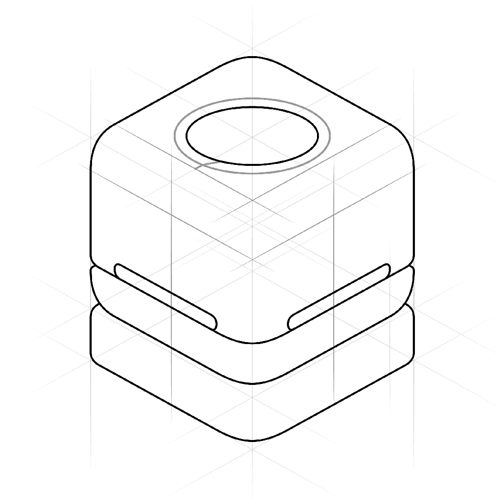
Step 10: Circular Cap

To construct a circle in 3D, the box on top of the cube needs to be divided evenly with construction lines. To ensure the lines are parallel to each face of the box and centered, tick marks are added at the midpoint of each of the segments on the top square.
Starting with the left side, we get a shorter, deeper curve because the bounding box angle is acute on that side. On the top, the curve is long and flat because the bounding box angle is obtuse on that side.
The curve on the right side is a mirror image of the one on the left. Extra construction lines may be needed to control this geometry.
Step 11: Seam and Hole Features

As seen in the multi-view drawing, the machine top enclosure snap-fits into the machine bottom enclosure. To draw this feature, another parallel box is added above the second one, providing a new plane to draw in. Once again, the arc bounding this corner is the same as the other arcs.
The seam is articulated by small curves on each end. The sweep of the curves here follows the same rules as circles- the obtuse angle makes the upper curve long and shallow, and the acute angle of the lower curve makes it short and deep.
As in the 2D drawings, the seam has an opening above it on each face. Construction lines are added again to provide a boundary for the openings. The vertical lines are coincident with the ends of the arcs on the machine bottom, and the lines for the tops of the holes are equally spaced to make the holes the same on both sides.
Step 12: Contour Lines
- This video has no sound -

Contour lines in fine art are basically the outline of the shape. In design sketching, however, contour lines are the lines that trace the surface of an object to communicate the shape. In the examples above, the heavier outlines are the object's perimeter, and the thinner lines are the contour lines.
- In a simple rounded cube, 3 continuous contour lines tell us there are no surface features.
- With a semi spherical indentation on the top, we see a single elliptical edge contour.
- This example shows an indentation with raised walls and sharp edges at each crease.
- This indentation has rounded edges. The crossing contour lines show us the radii of each curve, and the elliptical ones on top communicate the overall size and thickness of the feature.
- A more complex indentation shows us rounded edges and communicate the depth and shape.
- This organic form also only needs 3 continuous contour lines to communicate the shape.
To add detail and realism to this sketch, another ellipse is added within the circular shape on top. This will serve as a reference for the indentation on top of the enclosure.
Straight construction lines are useful for any kind of construction, including curved contour lines. These are added vertically intersecting the crossed construction lines on top of the cube. The skewed line from the outer contour to the inner circle will make the ring look as though it's recessed. The contour tracing this surface is the same radius as the contour on the end. The construction lines provide targets and tangent references for the arc.
A slight curve on the top and bottom of the slot are all that is needed to communicate that these edges have depth and are also rounded. Another curve, following the construction lines, shows that the top edge of the base is also rounded.
Step 13: Line Weight + Other Details

The holes on the sides are given depth by adding parallel lines recessed on the inside, and a short segment of the lower contour line turns along this edge.
The cap also has depth, and the edges will be rounded. Two straight segments are added to the cap.
Curves are added to the ends following the rules of thumb about curves and construction lines mentioned earlier.

With the contour lines in place, line weight can now be assigned with pens, making the drawing permanent.
- Heavy: The outer edge of the drawing (most depth to background).
- Medium: The edges with lesser depth (edge of cap, spatial edges of slots).
- Light: Seams and creases (interface between base and enclosure, seam between machine top and bottom).
- Extra Light: Contour lines
In the next lesson, you'll learn about light, shadow and shading to bring some realism and detail to your drawings.
Step 14: Shading: Visualizing Form
- This video has no sound -
Now that you know the basic concepts, you can apply them to a sketch. The gray scale markers are the best tool for this step, but you can fake it with cross-hatching if you'd rather keep it simple. In the video, I'm working with four different shades of marker (N0-N8), which is really all that's needed for this level of drawing.

It's always smart to start with the lightest shade- you can always make a drawing darker, but you can't make it lighter with the tools we're working with. The construction lines provide regions to shade, such as the area between the square on top and the circle. Use the N0 for mid-tone areas. The N0 is used for the mid-tone areas on the side of the drawing as well. Notice the rounded edges are left white.
The base of the machine enclosure will be a different material to articulate the geometry. The next darkest marker is a good choice here.

The back side of the cube will have a core shadow. Notice that the shading on the rounded corner to the left curves up, since it's a partial sphere. The edges of the shading should follow the surface curvature, more or less.

In this step, darker tones are added to the flat sides and lower curve on the back of the object. Brighter highlights are left on all of the upper edges of the parts. A darker core shadow is added around the bottom edge of the base.

The dashed lines demonstrate the chosen light direction. The lines are parallel, providing points for the corners of the box to be projected onto the ground. The outline should be parallel to the top of the cube on the top and side, then a straight line connects the edge to the bottom corner.
If you're not sure exactly how a shadow should be cast, all you have to do is put any object in direct sunlight and move it around- you'll get the idea intuitively and eventually you won't even have to think about it.

The darkest areas of the drawing are the slots in the sides, so those are shaded with the N8 marker. The N6 marker is used for the cast shadow.
Finally, the cap casts a small shadow on the recess on the top, and the underside of the recess gets core shading.
Step 15: Where to Go From Here
There it is, your crash course in design sketching. My hope is that you picked up the skills that will give you the confidence you need to start cranking out ideas on paper.
I can't stress enough the importance of practice. This skill takes a lot of patience and a lot of time to develop. As you can probably tell from the sketches I produced in the videos, I'm no expert at this, but that really doesn't matter. I'm good enough at it for my own purposes, and with some practice you will be too.
Here's a list of my favorite resources for ID sketching if you want to dive deeper.
Learning Resources
- The Design Sketchbook is the best formatted and most comprehensive resource I know of. The website has a free PDF book, and the Youtube channel is awesome.
- Coroflot has a lot of great portfolios of ID sketching.
- Spencer Nugent also has a great Youtube channel with dozens of videos on everything from drawing to rendering to shading to digital painting.
Other Tools
If you want to get into digital painting and drawing, there is no shortage of tools for you to choose from. Digital a few advantages over analog tools, not the least of which is the Undo command.

Autodesk Sketchbookis a powerful digital drawing an painting app for desktop and mobile. It works really well with an iPad Pro with the Apple Pencil in my experience, but there are lots of other options when it comes to interfaces, styli, tablets, etc.
They also have a great Youtube channel with plenty of tutorials.

Graphic is another great cross-platform app by Autodesk. It's a vector drawing app, which means you have a lot more control of lines and shapes once you draw them. If you're more of an engineer type who likes to use a ruler, this might be a good choice.
Anyway, have fun, and be sure to share whatever you make with the rest of us!


