

Introduction: Cutting Coves on a Table Saw - a Fusion 360 Virtual Project


Cove cutting on a table saw is a common practice to make rounded grooves and mouldings.
You slide the workpiece across the table saw blade at a skewed fence angle, and you end up with a nice concave groove. When you tilt the blade you get even more interesting asymmetric profiles. But how do you predict what the cut profile will look like? Well, I share a parametric Fusion 360 file where you can change the fence angle (skew), blade tilt, and blade height; and see the resulting cove profile before cutting any real wood. If you use Fusion 360 this model is really easy to use.
Supplies
Autodesk Fusion 360 installed on your computer
Step 1: Cove Cutting


I assume that you are familiar with table saw cove cutting, and have a jig to do it safely. I will not describe the actual cutting process here. For that you can consult the many DIY links available on Instructables, Youtube, etc.
https://www.instructables.com/Making-Cove-Profiles-on-a-Table-Saw/
https://www.instructables.com/Cove-Cuts-on-a-Radial-Arm-Saw/
Cove Cutting with a Table Saw | Woodworking
How to Make Cove Cuts with a Cove Cutting Table Saw Jig
There are a number of on-line calculators available to determine skew and tilt parameters, but they don't show the resulting cove profiles.
The picture above shows a range of profiles you can get from changing the skew angle and blade tilt.
Step 2: Design and View Your Cove Profile


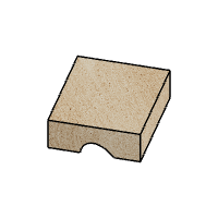
Download and open the attached Fusion 360 file “Cove Cuts.f3d”. In the design space you will see an 8” by 12” by 3.5” thick workpiece. This is for modeling purposes only to show the cove profile; in real life you will probably use a different size piece.
The saw blade is assumed to be standard 10 inch diameter, 1/8” kerf.
I have provided screen shots for all the Fusion 360 steps below.
To enter your desired parameters go to Modify > Change Parameters. This will open a window with three user parameters Tilt, Skew, Blade_Height. In the column “Expression” enter a new value, e.g. 15 degrees for Skew. Click OK and the new profile will show on the workpiece. To view it head-on click on the “Look At” icon (bottom center) and select the workpiece face with the cove. Use the Inspect > Measure menu to get measurements of the cove dimensions.
You can also capture the image of the cove and then print it out: File > Capture Image
Each parameter is limited to a range as follows: Tilt 0 - 45 degrees, Skew 0 to 80 degrees, Blade_Height 0 to 3 inches. This prevents the model from breaking when presented with extreme or unreasonable values.
That’s it. When you find a cove profile you like you can set up your table saw and jig with the desired skew and tilt parameters. Cut the cove by making consecutive cuts, raising the blade slightly for each cut, up to the final height.
Attachments
Step 3: Some Cove Designs


Combine multiple cove cuts for some interesting profiles. I am showing some modeled profiles as examples.
Cove cutting can be a dangerous operation. As always, be careful when you use your table saw in real life! Raise the blade in small incremental steps. Secure the workpiece and use push blocks, safety glasses, ear plugs, a dust mask, and common sense.


