

Introduction: DIY Digital Readout for Drill Press


Hi
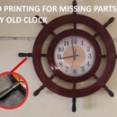
Welcome to my first Instructables. Let's hope it will be a good start. I'm a hobbyist, and a student, So I just started to invest in tools. I don't have a lot of money to buy expensive tools so I bought some affordable tools for my needs to upgrade them along the way. I need a drill press for my project so I ended up with a cheap Drill Machine Stand, it will help me turn my hand drill into a drill Press
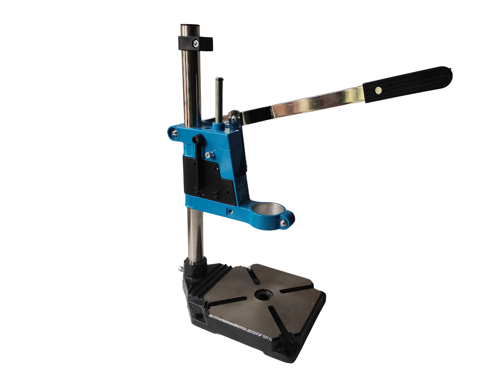
My projects require drilling holes to a very precise depth. But this device does not have a mechanism to measure it accurately, it only come with a plastic scale which is not accurate and not visible
So I decided to modify this drill press with the power of electronics and 3d printing. we are wing an ordinary digital caliper for measurement and interface that data to a screen with a microcontroller. it is possible to read the data from the LCD screen of the caliper but it has poor visibility. also, it only shows 0.0mm accuracy. but by interfacing the data we can get up to 0.00mm accuracy. also, the screen is visible in the low-light situation
What I did
- Added a digital scale with an OLED display by hacking into a digital caliper
- Added an LED light at the bottom for good visibility
Let's see how it is done
Supplies

- Arduino nano (ATmega328P 5V)
- Digital Caliper
- 0.91 inch 128x32 I2C OLED LCD Display
- Led ( red)
- 220-ohm resistor
- 10uf capacitor
- Mini USB cable
- M3 screw kit I use (also need m3 nuts)
- Rainbow Color IDC Ribbon Cable
- 30 AWG Stranded Tinned Copper Wire
- The Drill Press Stand I am using
Tools
- 3d printer or 3d printing service
- Glue gun
- Screwdriver set
- soldering iron kit
Step 1: Ideas to Reality in Fusion 360
Let's see how I made this. First off all I took a photo of the drill press form side ,
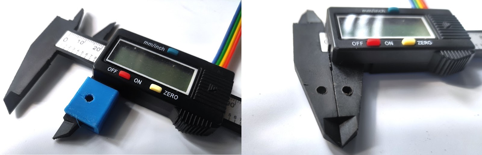
After that, i measured one feature that is visible on the photo
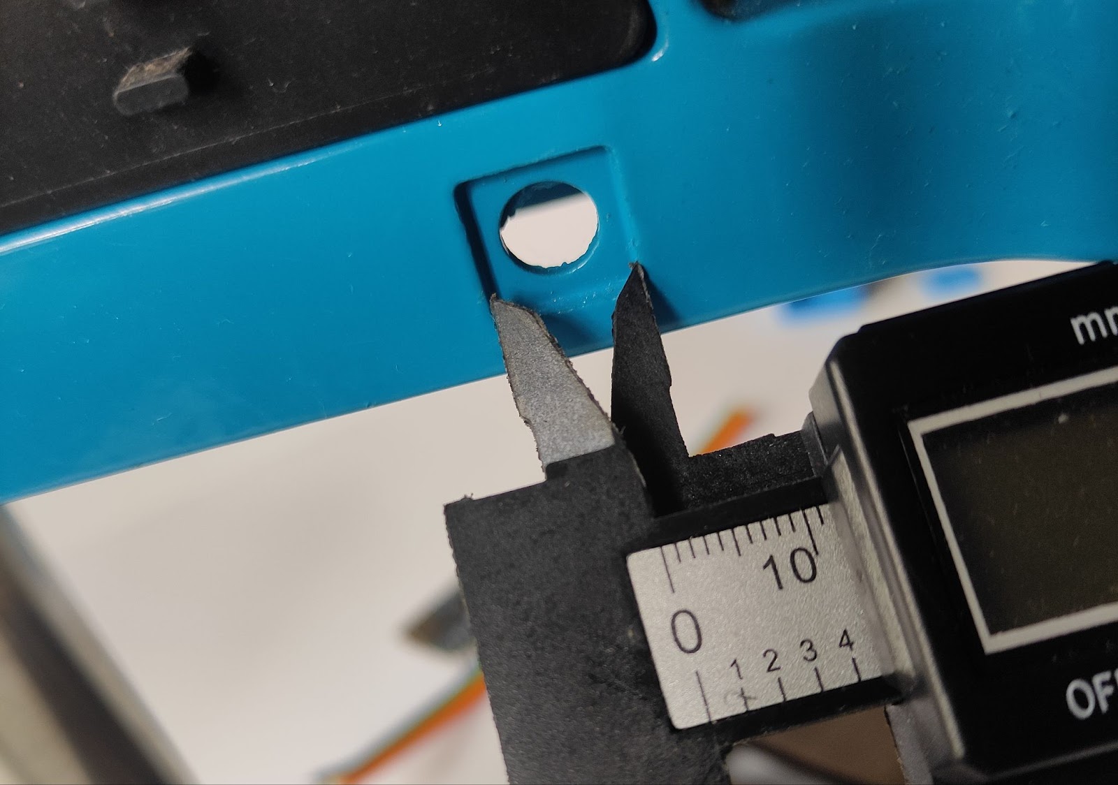
I measured this part with is a 12mm
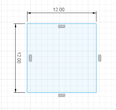
After that i made a sketch with 12mm square
Now i'm going to import this image as a canvas to fusion 360 and scale this image with reference squared
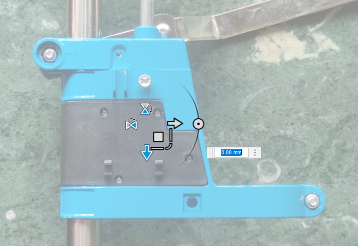
Now we can complete our design with this reference to the canvas
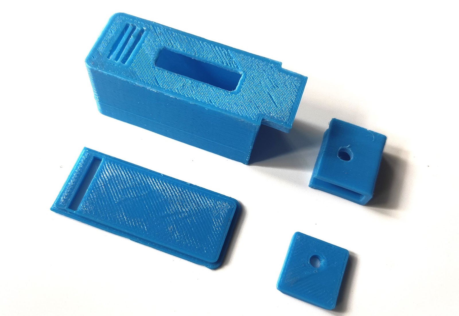
This is only the beginning stage of the design after that I got models of Oled, Arduino, and digital vernier caliper from the Grabcad website, after importing all of these models I designed an enclosure around it
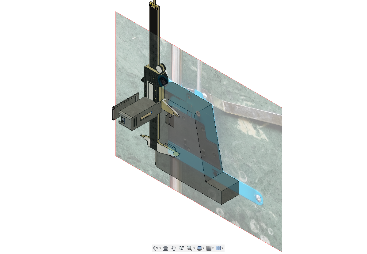
I exported all of the models into an STL file and 3d printed it. All the STL files are attached below


Step 2: Hacking in to Vernier Caliper
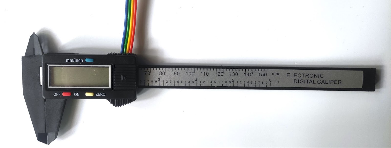
We are going to use a cheap vernier caliper for getting the measurement data. so let's look at how to hack into vernier caliper,
This instructables helped me a lot to understand how to get data from it
First of all, disassemble the caliper by removing the screws on the back side
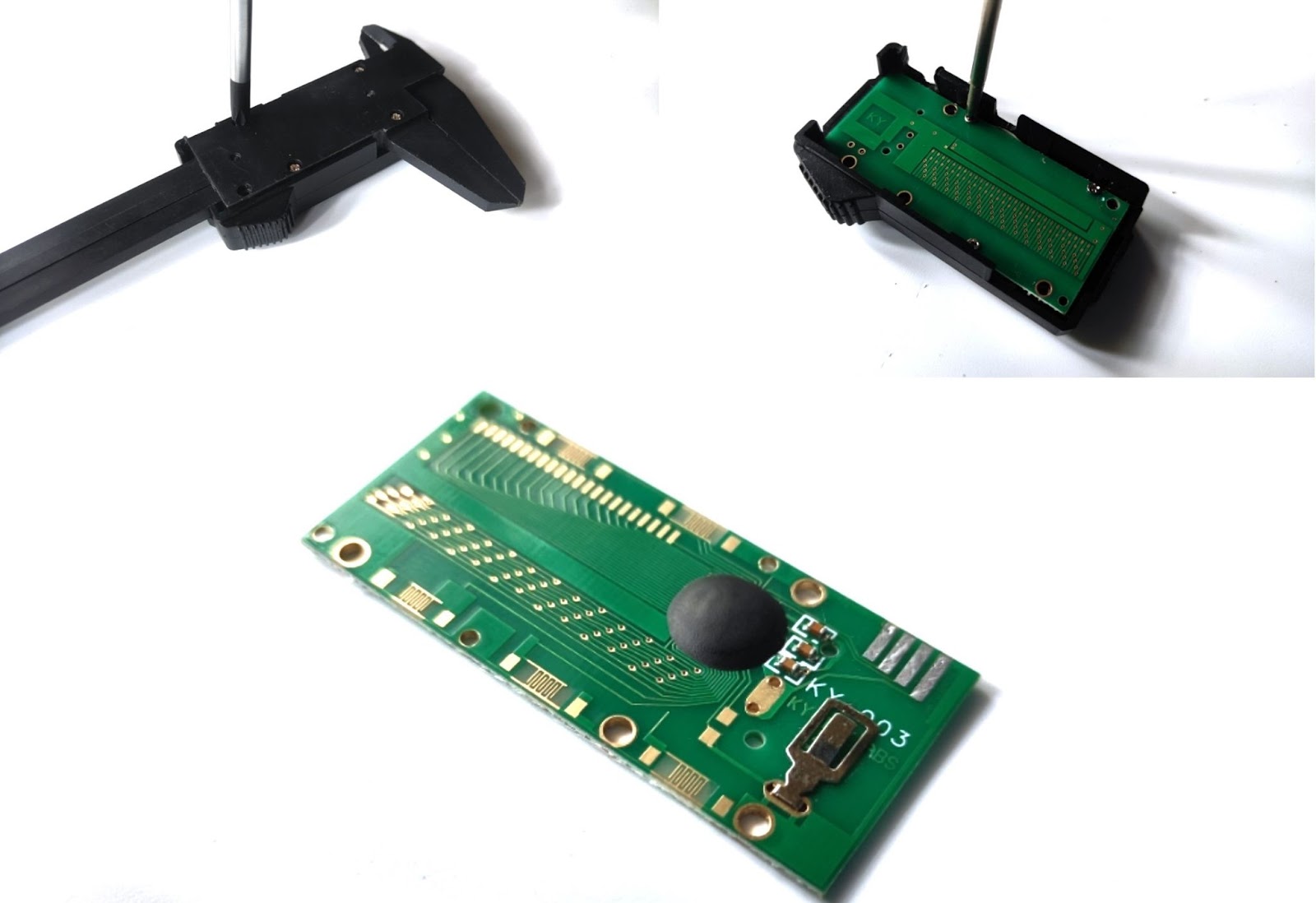
communication between Arduino and the caliper is done through i2c,so we have 4 soldering pads GND,SDA,CLK,VCC.
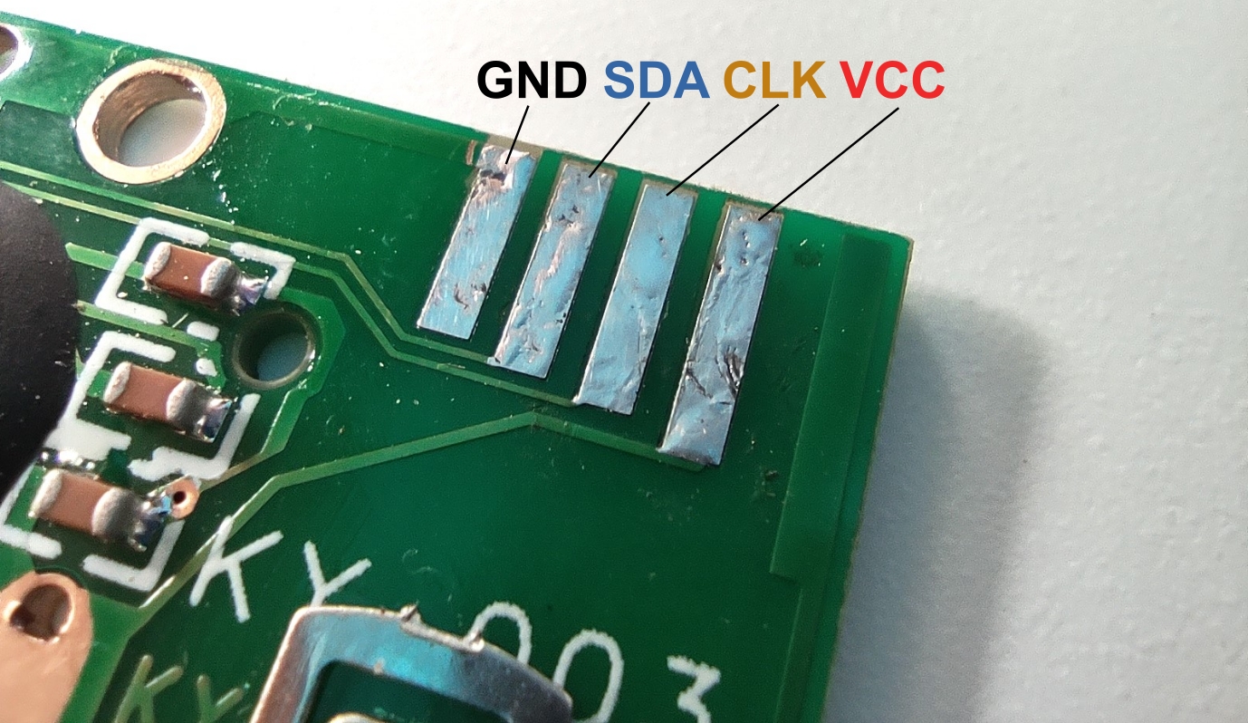
Now solder 4 wires into it, the length of the wire needs to be 10cm
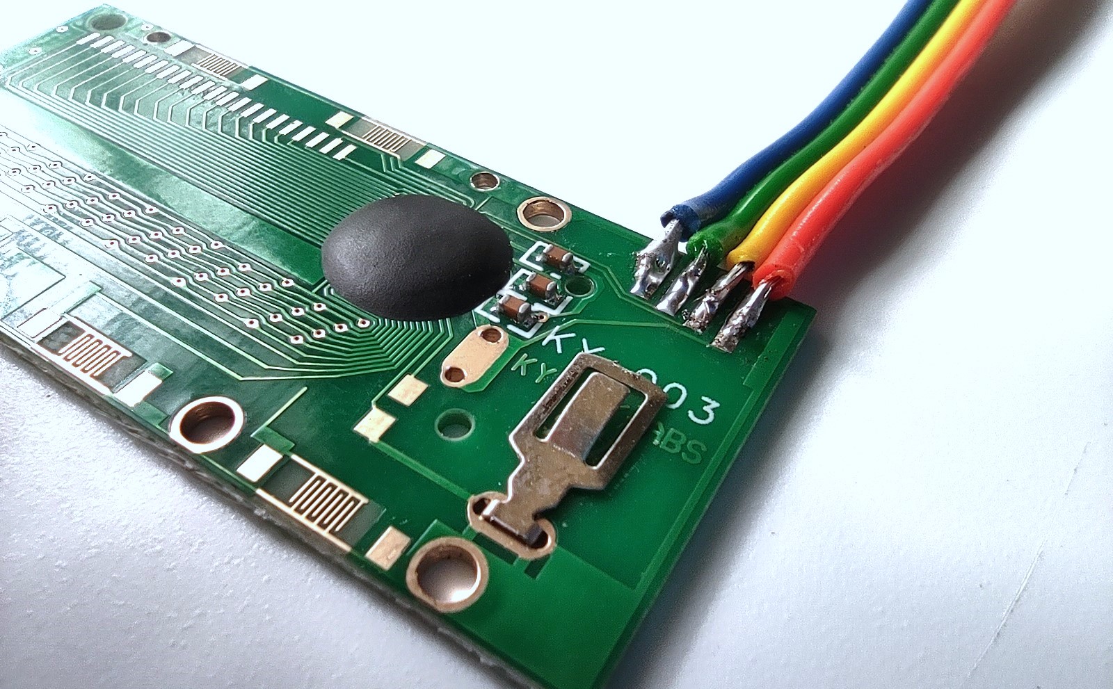
Make a hole on the front plastic cover of the caliper with a soldering iron for the 4-wire input
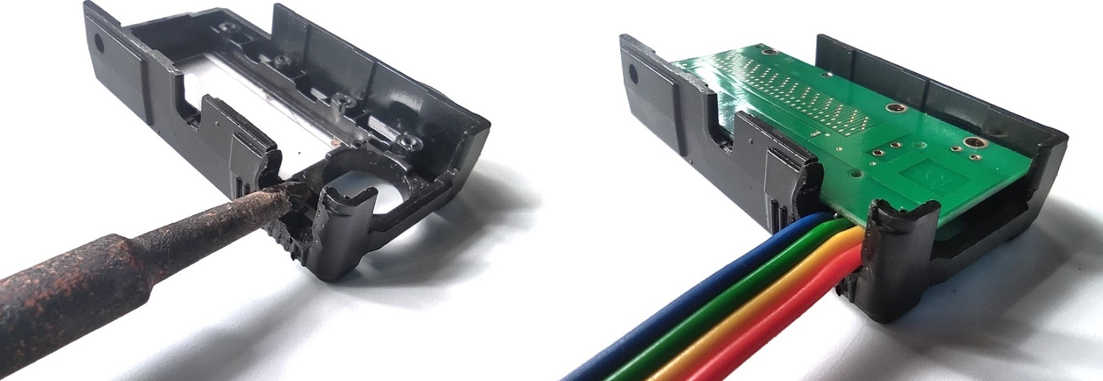
reassemble the caliper also don't forget to remove the battery
Now we need to drill 3mm holes into the caliper arm using 3d printed parts for reference
Step 3: Circuit Diagram

We are using an Arduino Nano for interfacing measurement data from the clapper to a small OLED display, this circuit is pretty much simple. Add that 220R current limiting resistor to the GND connection of the caliper. Also, add a small 10uf cap for the 3.3V and a LED. Connect the clock and data pins to digital pins D12 and D11 for the i2c serial communication. Now we could add an OLED display for displaying the data, don't forget to remove the battery of the caliper
Step 4: Assembling the Circuit
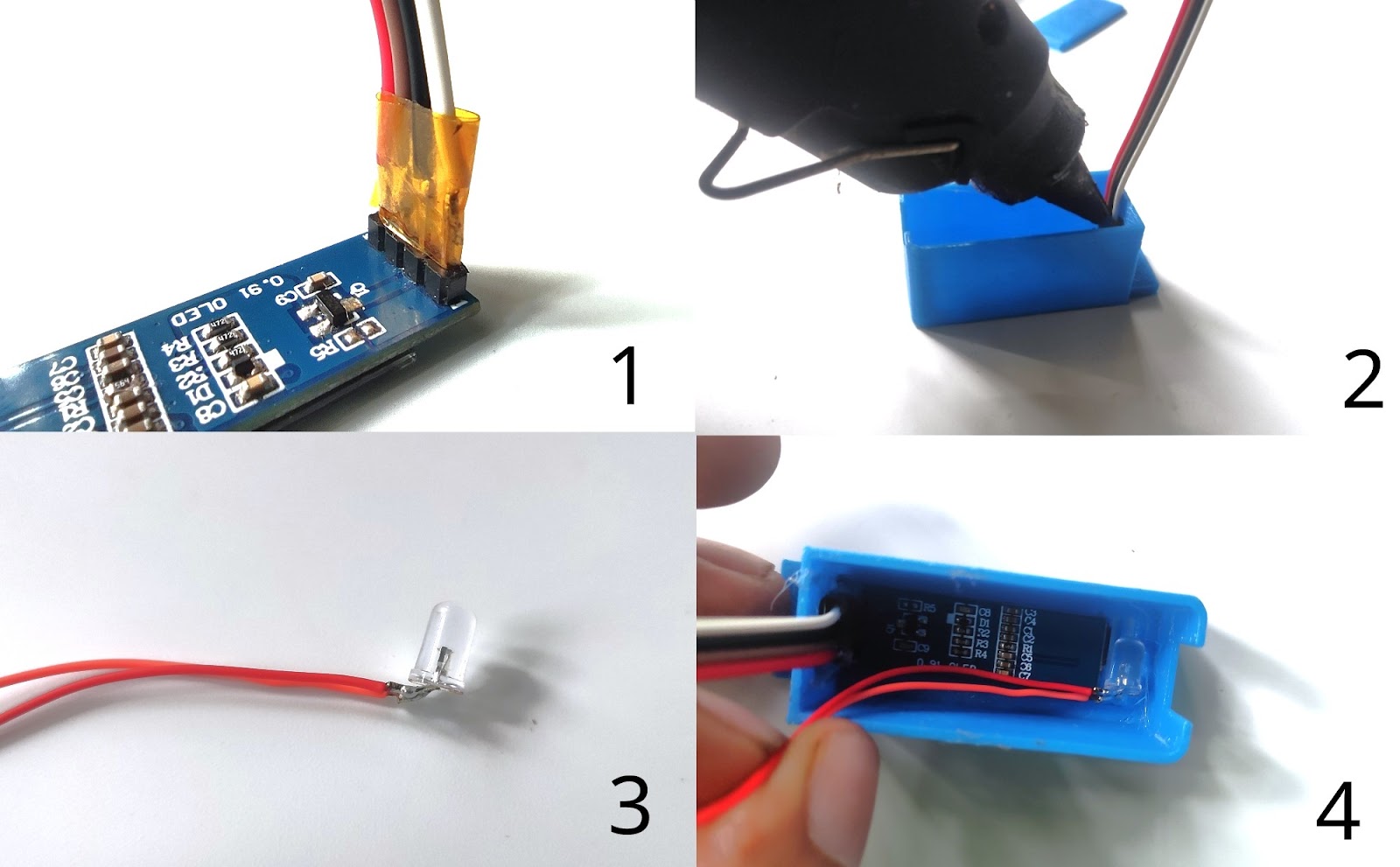
- Solder 4 wires into OLED and insulate the wire joints using heat shrink or insulation tape
- Fix the OLED into 3d print with some hot glue
- Bend the led terminal into an L shape and solder 2 thin wires to it
- Hot glue the LED near the OLED
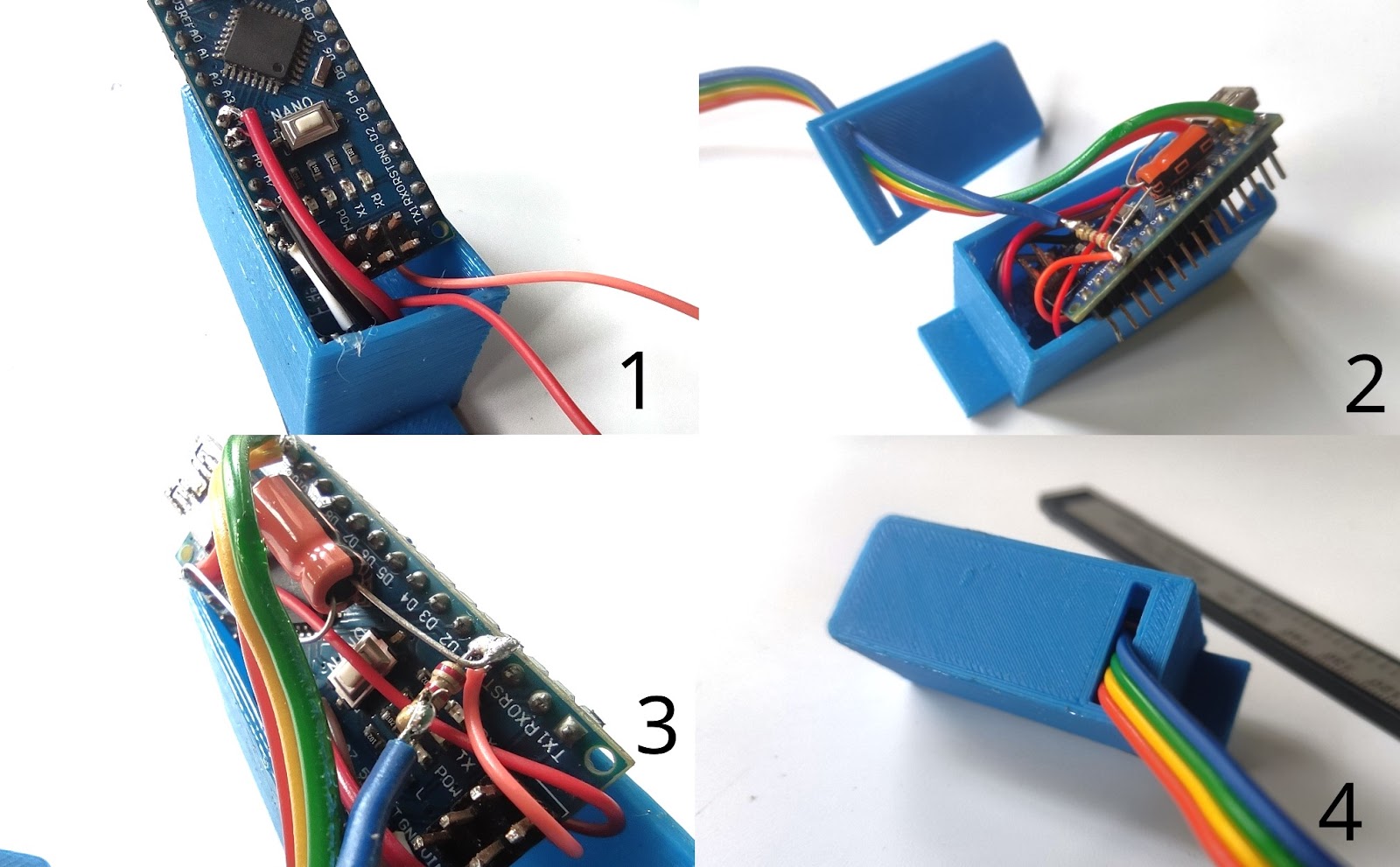
- Solder oled wires to Ardiuno
- Bring the 4 wires from the caliper through the gap in the back plate
- Solder all of the wire according to the circuit diagram above
- Snap the back plate with little pressure
Step 5: The Code
After the circuit assembly, we will upload the code with Arduino IDE
#define CLOCK_PIN 12
#define DATA_PIN  11
#include <SPI.h>
#include <Wire.h>
#include <Adafruit_GFX.h>
#include <Adafruit_SSD1306.h>


#define SCREEN_WIDTH 128 // OLED display width, in pixels
#define SCREEN_HEIGHT 32 // OLED display height, in pixels


// Declaration for SSD1306 display connected using I2C
#define OLED_RESET     -1 // Reset pin # (or -1 if sharing Arduino reset pin)
#define SCREEN_ADDRESS 0x3C
Adafruit_SSD1306 display(SCREEN_WIDTH, SCREEN_HEIGHT, &Wire, OLED_RESET);

void setup()
{
  Serial.begin(9600);
    // initialize the OLED object
  if(!display.begin(SSD1306_SWITCHCAPVCC, SCREEN_ADDRESS)) {
    Serial.println(F("SSD1306 allocation failed"));
    for(;;); // Don't proceed, loop forever
  }
  display.clearDisplay();
  display.setTextColor(WHITE);
  display.setRotation(2);
  pinMode(CLOCK_PIN, INPUT);
  pinMode(DATA_PIN, INPUT);

}


char buf[20];
unsigned long tmpTime;
int sign;
int inches;
long value;
float result;
bool mm = true; //define mm to false if you want inces values


void loop()
{
  while(digitalRead(CLOCK_PIN)==LOW) {}
  tmpTime=micros();
  while(digitalRead(CLOCK_PIN)==HIGH) {}
  if((micros()-tmpTime)<500) return;
  readCaliper();
  buf[0]=' ';
  dtostrf(result,6,3,buf+1); strcat(buf," in ");
  dtostrf(result*2.54,6,3,buf+1); strcat(buf," cm ");


  if(mm)
  {
  display.clearDisplay();
    display.setTextSize(3);
  display.setCursor(5,5);
  display.print(result);
   display.setTextSize(2);
  display.print("mm");
  display.display();

  }
  else
  {
  display.clearDisplay();
  display.setTextSize(1);
  display.setCursor(0,0);
  display.print(result);
  display.display();

  }
}
void readCaliper()
{
  sign=1;
  value=0;
  inches=0;
  for(int i=0;i<24;i++) {
    while(digitalRead(CLOCK_PIN)==LOW) {}
    while(digitalRead(CLOCK_PIN)==HIGH) {}
    if(digitalRead(DATA_PIN)==HIGH) {
      if(i<20) value|=(1<<i);
      if(i==20) sign=-1;
      if(i==23) inches=1;
    }
  }
  if(mm)
  {
    result=(value*sign)/100.0;
  }
  else
  {
  result=(value*sign)/(inches?2000.0:100.0); //We map the values for inches, define mm to false if you want inces values
  }

}
Step 6: Joining Two 3d Printed Parts Together


I designed these parts with easy 3d printing in mind so I made this in 2 parts so I can join them later. I joined them by melting them with a soldering iron. I put the temperature of the soldering iron around 340c. and put 2 prints together, and melted the edge together
Step 7: Attaching to the Drill Press


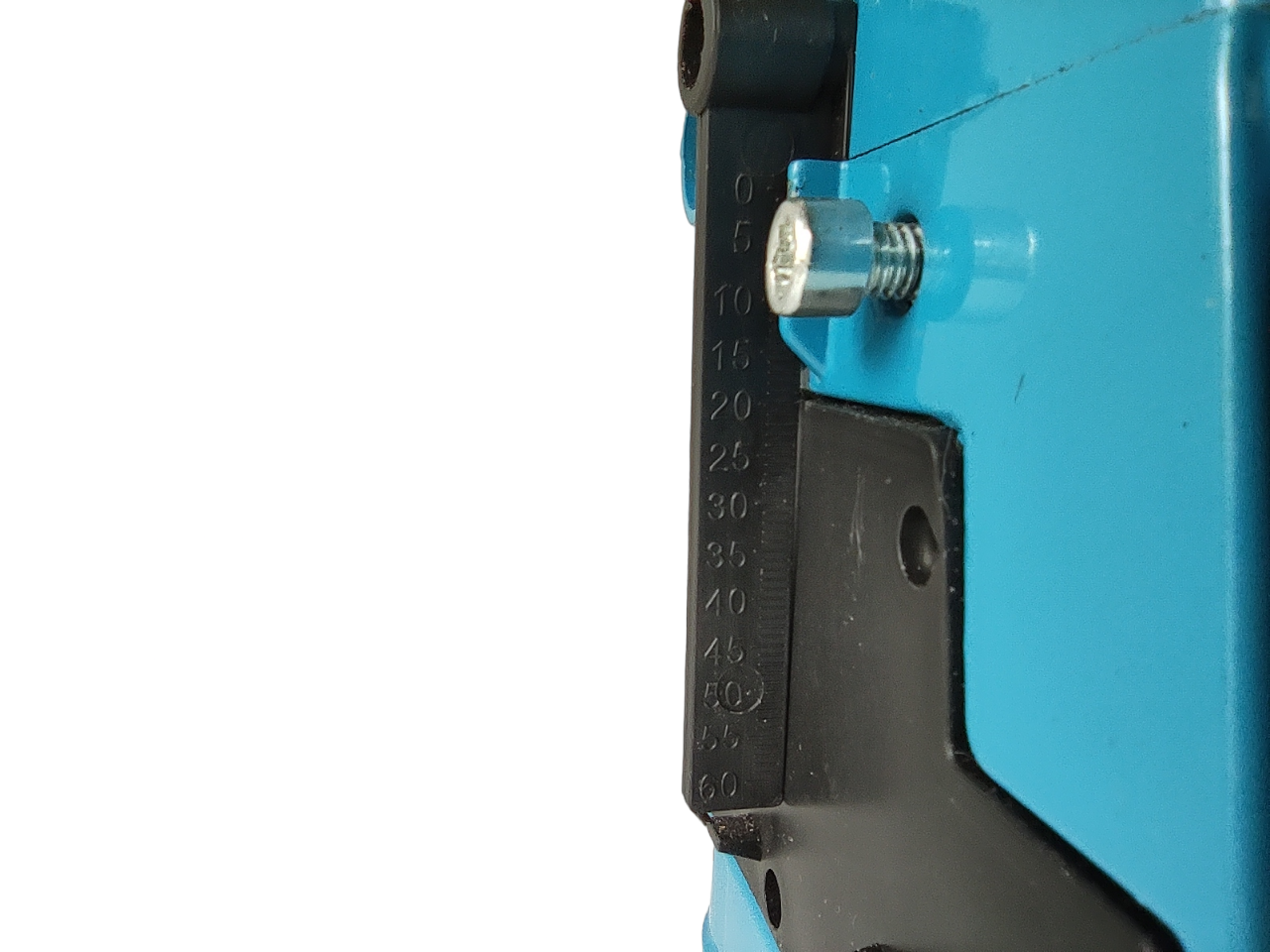
- Remove one side plate of the drill stand
- Make a hole into the side plates and screw the caliper arm
- Screw in the caliper arm to the side plate with the m3 nut and bolt
- remove the plastic scale
- screw in the top part of the caliper, this will also hold our circuit
Step 8: Operation
Wow! Now we are done with the build. let's test it
We power circuit with a USB power source
If the OLED screen shows a random value during boot-up, then you can press the zero button to bring the measurement value to 0.00mm. If the measured length is not correct please make sure this unit is selected mm in the caliper. Press the mm/in button to change the measurement unit
When we press down the drill press we can see the travel distance in real time

First Prize in the
First Time Author


