

Introduction: Dimmable LED Panel


When I saw the LED contest it got me thinking on if there was anything that would be fun to make that used LED's. I'm not really an electrical guy so I thought it would be a fun challenge. I had been looking at getting a work lamp for some time so after thinking about making something with LED's I decided to make my own work lamp. While I was looking up LED's for this I was noticing all the other colors and then I noticed the UV ones. I used to love black lights when I was younger so I thought it would be cool to make another one that was a UV/Black light version. I think this ended up costing me about $30 each for the lights ($20 was just for the LED strip and I had a lot of the materials already). I don't think that is that much better than what you can find at the store but this one is dimmable and I got to learn a lot while making it.
Attachments

Step 1: Electronics


As I am electronically inept it took me a good amount of searching to really figure out what all I needed and how I wanted to make it work. Here is a list of the products I bought for this:
- Fuse holder with fuses. I bought this as a precautionary measure. A lot of the parts were from Ebay so just in case I wanted a fuse in there.
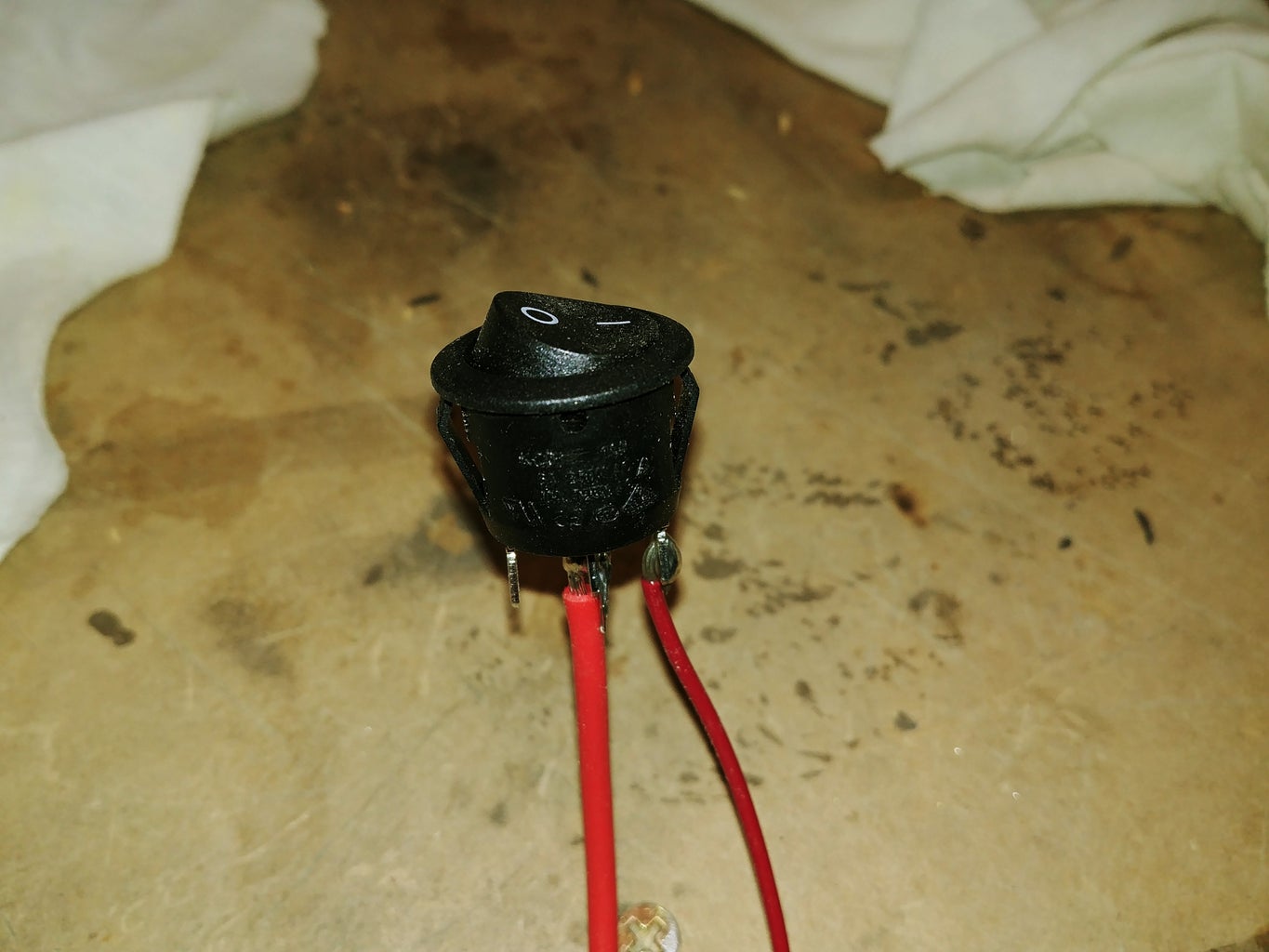
- Power Switch. Just a cheap power switch.
- Power supply with plug. This was cheaper on Ebay and came with the plug as well. This wasn't UL certified which the LED strip said it required but that's why I have a fuse.
- Dimmer. This one was dirt cheap but shipping took a long time. Like two months long. But I wasn't in a rush. I also lucked out that this one was screwed together because I intended to use the internals and not the housing it came in.
- LED strip. I chose these because of their brightness. I wanted something bright without having to use a whole 16 foot long strip of lights. WARNING: Even though I bought and used these I do not recommend them. These were soldered in the middle (shown in picture) even though they say in the description they can be cut every third LED they can not due to this. After contacting the company they would only do their standard return which meant not getting reimbursed for the shipping cost. I got them to work but I no longer will buy anything from them. So, if anyone has a good place to buy LED's I would be interested to know for any future projects. Rant over.
Step 2: Laying Out the LED's on the Panel


For the panel that will be holding the LED strips I ended up using a sheet of aluminum. I was originally just going to use a MDF sheet for both the front and the back but there was a piece of scrap aluminum at work that was large enough to use. So why not use aluminum. The panels dimensions are 5.5 inches by 7.5 inches. The way I laid out the LED strips meant that it would be a lot of smaller strips soldered together. I haven't done much soldering so this was going to really test my soldering skills but I liked the layout so I stubbornly stayed with the harder but better looking design. See PDF for the layout dimensions I used.
NOTE: When laying out the strips you want the the connections to be the same on either side of the gap. This will simplify soldering these together. See pictures for example.
After all of that soldering it was time to test it and luckily everything lit up. Soldering job successful.
WARNING! If you have a Kidde fire extinguisher make sure it is not recalled. They just had a large recall on many of their fire extinguishers. Both of the ones that I have were recalled.
Step 3: Making the Frame


I designed this so that there would be a frame with a front panel with the LED's on it and in between that and the back panel would be all the wiring and electronics.
To make the frame I cut a 2x2 board that I had so that the inside dimensions would be 4.5 inches by 6.5 inches. It is an inch shorter than the panels because I was going to put a half inch long by a quarter inch deep step into it so that the panels would be recessed into the frame. I used my router to give me that step on the front and back of the frame. Once they were cut I tested the fit and panel just fit into the recess area.
Step 4: Fitting the Plug


Now that the frame pieces were all cut it was time to cut the holes to fit the plug, power switch, and dimmer into the frame. I laid out the components to know where I wanted them located and then went onto making them all fit.
For the plug I first drilled a hole that was about the size of the end that plugs into the power supply. Now that that hole was drilled I needed to make room for the rest of the plug to fit. To expand the hold I used a chisel and kept making it deeper and deeper until the plug just barely started to stick out from the wood.
Step 5: Testing (You Should Probably Do This Earlier Than I Did)


I should have done this earlier but this was the point that I realized that I should probably connect all of the components and confirm everything worked. Luckily everything worked great which meant all the parts were good and how I planned on wiring it was good.
I don't have a wiring diagram but it is pretty simple. The negative from the plug goes to the negative in on the dimmer. The positive from the plug goes into the fuse which then goes into the in on the switch. Then out from the switch then goes into the positive in on the dimmer. The LED panel then connects the out on the dimmer with its correct positive and negative spots. If anyone experienced with wiring sees anything wrong please let me know.
Step 6: Fitting the Power Switch


The power switch was easy. This style just required a hole that was tight enough for this to stick into when inserted. I believe this was a 3/8 in hole for this switch.
Step 7: Fitting the Brightness Adjuster


This was the more tricky one. The best way I came up with to mount this was to drill a hole and then chisel enough room to allow the potentiometer to sit flush with the outside of the frame. I forgot to document making that slot. I guess I was slacking a bit. I then made a plate that would be screwed onto the frame and would allow the potentiometer the fit through and bolt onto. I made the plate out of some leftover nylon sheet that I had from a previous project.
Step 8: Glue the Frame

Now that I could fit all the electronics into place it was now time to glue the frame together. You want to make sure to wait and do this until the previous steps are complete or else you may not be able to fit the electronics into the frame.
Step 9: Making the Lamp Arms and Clamp


While the frame was gluing I decided to make the arms to the lamp. I made these arms by cutting a 2 x 4 into 0.75 in strips. This resulted in four 0.75 by 1.5 inch arms. (They are 1.5 inches wide because 2 x 4 boards are actually 1.5 x 3.5) The board I was using was probably around 2 feet long. Two of these boards I kept that length and just removed a 0.75 x 0.75 piece form opposing corners. I then drilled a 1/4 in hole in the ends and rounded them. This will allow me to attach these together with a bolt and provide adjustment.
I then cut some smaller pieces that I used to mount to a cheap clamp so that I can mount these lamps almost anywhere.
Step 10: Adding the Frame Mount


Now that the frame is all done gluing it is time to attach its mounting point. To do this I cut a 0.75 x 1.5 inch slot on the bottom so that I could insert a cut off piece from the previous step. I made this slot with my router. This also has a 1/4 inch hole through the cut out section of the mount.
Step 11: Attaching the LED Panel and Back Panel


Now that the frame is all complete ti is time to make the back panel and attach it and the front panel to it. For the back panel I just cut out a 5.5 x 7.5 inch piece from some 0.25 in MDF that I had. I then screwed that onto the back of the frame. Again, slacking on not taking pictures. There is a picture later that shows the screws. For the front panel I drilled a hold in the middle of each side and then used some small screws I had laying around to attach in to the frame.
Step 12: Finalizing the Electronics


Not that I have the frame, front, and back all ready to go I needed to trim, solder, and connect all my wires and connections. For the power button you want to make sure to feed the wire from the fuse out to hole to solder it as the fuse wont fit through the hole for the switch. I found this out the hard way.
Step 13: Final Assembly


With everything fitting good it was time to apply any desired finishes to the wood. I chose a darker stain for everything. You can do this before the previous step as you will probably need to remove some of the electronics to apply the stain or finish. Then you just need to secure the electronics in place and you are good to go. Just push the power button into its hole and I added a screw to keep the plug into place.
Step 14: Adding Batter Power (Optional)


This step is completely optional but I wanted to be able to run these off of battery power just in case I needed them for something where I didn't have an outlet near by. I ordered these 12 volt battery holders to provide me with an optional battery supply. But I also didn't want them on there all the time so I decided to add Velcro to them so that I could remove them until I needed them. NOTE: Make sure the battery case you use has the same connector as your power supply so you can just plug it in and go. Also, it is probably best to use the softer side of the Velcro on the lamp so that it doesn't poke you during handling.
Step 15: Complete


It is now complete. All you need to do is connect the arms to the head and you have a great work light or whatever you want. When you attach these it works best to add some sort of locking washer so that it holds its position and does not slide. If you don't want a clamp on the end you could easily make a base for this and have a desk lamp or attach it straight to your workbench as well. This can also be made with any color of LED strip light. so if you want a blue or red one for something then that will also work.

Participated in the
Epilog Challenge 9

Participated in the
LED Contest 2017


![Tim's Mechanical Spider Leg [LU9685-20CU]](https://content.instructables.com/FFB/5R4I/LVKZ6G6R/FFB5R4ILVKZ6G6R.png?auto=webp&crop=1.2%3A1&frame=1&width=306)


