

Introduction: DIY Lab Bench Power Supply [Build + Tests]
![DIY Lab Bench Power Supply [Build + Tests]](https://content.instructables.com/FSS/JKNM/JXITWM03/FSSJKNMJXITWM03.jpg?auto=webp&fit=bounds&frame=1&height=1024&width=1024auto=webp&frame=1&height=300)


In this instructable / video I will show you how you can make your own variable lab bench power supply which can deliver 30V 6A 180W (10A MAX under the power limit). Minimal current limit 250-300mA.
Also you will see accuracy, load, protection and other tests. They should give you better idea, to easily decide, is it worth making it yourself.
Provided Amazon links are affiliates
Main Tools You'll Need:
- Drill: https://amzn.to/2U5QQmL
- Step drill bit https://amzn.to/2LnNlX7
- Diagonal cutting pliers: https://amzn.to/2E8vOz5
- Digital Multimeter https://amzn.to/2rf0EO3
- Soldering kit: https://amzn.to/2Q613Bf
Main Materials You'll Need:
- 36V 5A PSU https://amzn.to/2FEgYje
- Step-down 300W 20A module https://amzn.to/2VCozai
- Step-down module for 12V output https://amzn.to/2S6XAkY
- Voltmeter ammeter display https://amzn.to/2VCvnVx
- 100k Ohm 3590S potentiometers https://amzn.to/2Y35yzq
- Caps for potentiometers https://amzn.to/3cMJn4O
- Banana socket https://amzn.to/2IXZ8tG
- AC IEC 320 C14 socket https://amzn.to/2S2mKBi
- Power switch https://amzn.to/3eTBb4G
- Fan https://amzn.to/352JEh6
- Rubber feet https://amzn.to/3eNQtrq
- Electronic components box (local electronics shop)
Other Things You'll Need:
M3 screws, nuts, wires, crimp terminals, banana plugs, alligator clips.
You can follow me:
- YouTube: https://www.youtube.com/diyperspective
- Instagram: https://www.instagram.com/diyperspective
- Twitter: https://twitter.com/diyperspective
- Facebook: https://www.facebook.com/diyperspective
Step 1: Preview


Front, back and the inside shots of the power supply.
Like what I do? Consider becoming a PATRON! This is a great way to support my work and get extra benefits! https://www.patreon.com/DIYPerspective
Step 2: Components


All components that you will need and some close up shots of them.
Step 3: Making Front


In the front we need to make holes for the display, two potentiometers, two banana sockets and for the power switch.
For smaller holes metal drill bit works just fine, but for bigger holes you will need a step drill bit to drill the holes without cracking the box.
Step 4: Finishing Front


I would say this is the hardest part of the build - make a square hole at the top of the box. My solution was to drill many small holes, cut out bigger pieces and then sand to the right size. I works well, but it takes a lot of time.
If you know better solution, I'm all ears. It must be the easier way?! Right?
Step 5: Back


Now on the back, we need to make many holes for the fan, that it could exhaust the hot air and square hole for the AC socket. Nothing hard, just a lot measuring and drilling.
Step 6: Component Placement


We should plan the inside layout for the components. You want like AC connectors of the power supply to face the back and potentiometers of the 300W step-down module to face the front.
Also try to position those two components that the air from the bottom front would go through all the heatsinks.
Step 7: Rubber Feet


With screws in place, now we can find space to make additional holes for the rubber feet in each corner.
Step 8: All Wires

With all components in place now we can measure required wire lengths (how everything connects - later).
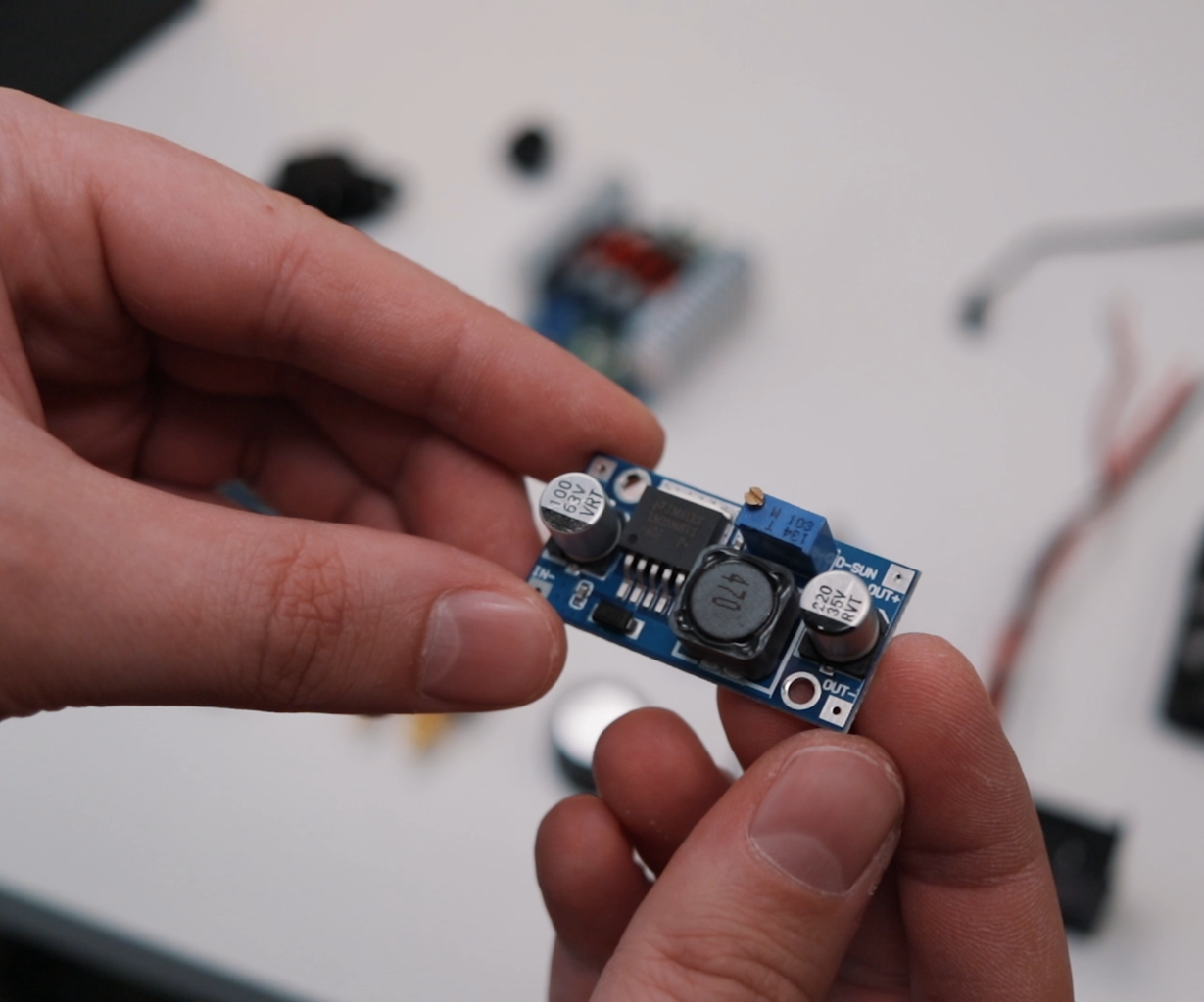
Step 9: Modifying the Module


But before connecting everything, we need to de-solder existing small potentiometers on the module (on my module you can see only one potentiometer, because I already de-soldered one).
We need to add extension wires that will go to the new multi-turn potentiometers.
- The middle wire from the module goes to the bottom connector on the potentiometer.
- The top wire goes to the middle connector
- The bottom wire goes to the top connector.
This way you will get that rotating potentiometer clockwise voltage or current increases and counterclockwise decreases.
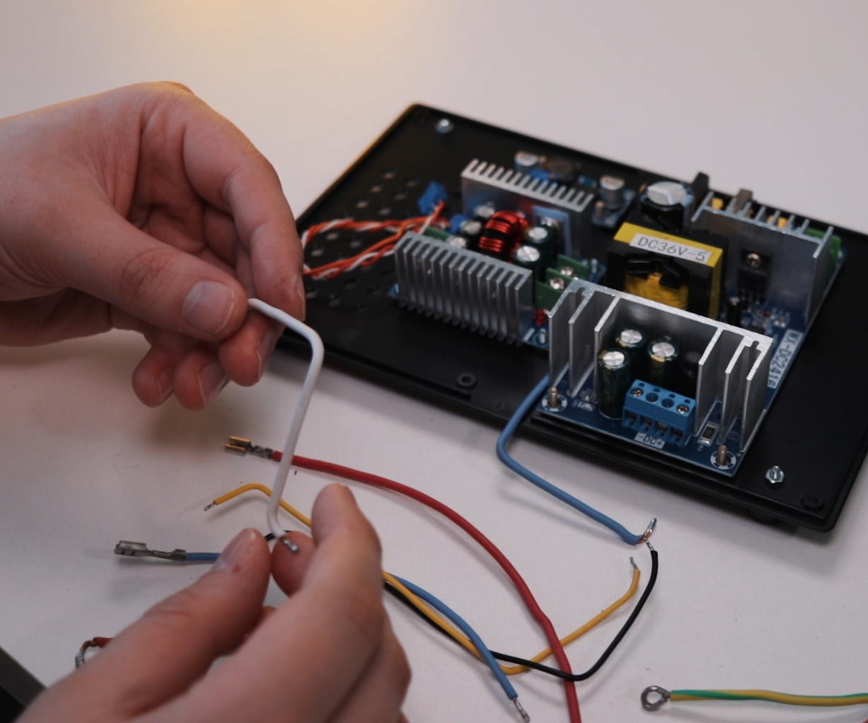
Step 10: AC Wires


AC, AC, AC, be really careful with it, or it could kill you. Always connect ground wire, it's a great safety feature.
For quick connection to the onboard AC socket and power switch at the front, I used these wire crimp terminals. On them, I added some heat-shrink tubing for the insulation.
Step 11: Wiring


4 wires goes from the 36V power supply. Thick (16AWG or thicker) wires go to the main 300W step-down module and thin wires to the additional step-down module. With this done, don't forget to power on the additional module and adjust output voltage to 12V.
Step 12: How Everything Connects


As from this wire mess it's really hard to follow, I added simplified view how everything connects together.
- We have connected live AC wire which goes from the onboard socket through the power switch to the power supply. The neutral wire goes to the other terminal and ground wire to the ground connection.
- Two thick wires go to the main step-down module and two thin wires to the secondary module. To it, comes wires from the fan and two thin wires from the display.
- The third thin wire from the display, which is usually yellow, goes to the red positive banana socket. To this same socket goes positive output of the main step-down module.
- Finally, black thick wire from the display goes to the negative connector of the main step-down module, and red thick wire to the black negative banana socket.
And that’s it, the circuit is complete. You additionally can fine tune voltage and current readings on the meter with two integrated potentiometers.
Step 13: Final Touches


With caps on, display wires in and all screws isolated, we are done.
One more thing that we could make are banana plugs for easy testing.
Step 14: TESTS


Few accuracy, load and other tests.
Step 15: TESTS


Few temperature and short-circuit tests.
Step 16: THE END


So, what can I say, as all parts cost only around $35, I think it gives good value considering the accuracy and performance of the power supply.
For me, this device will hugely ease up testing of all sorts of electronics for my future projects.
So if you are looking for a cheapest way to get above average accuracy and performance, DIY power supply like this might be the answer for you.
I hope this instructable / video was useful and informative.
If you liked it, you can support me by liking this Instructable / YouTube video and subscribing for more future content. Feel free to leave any questions about this build. Thank you, for reading / watching! Till next time! :)
You can follow me:
- YouTube: https://www.youtube.com/diyperspective
- Instagram: https://www.instagram.com/diyperspective
You can support my work:

![Tim's Mechanical Spider Leg [LU9685-20CU]](https://content.instructables.com/FFB/5R4I/LVKZ6G6R/FFB5R4ILVKZ6G6R.png?auto=webp&crop=1.2%3A1&frame=1&width=306)


