

Introduction: DIY Simple Wooden Ambient Light (ESP8266, WLED, WS2812B)


In this project I will show you how to make a simple wooden wall light with LED strip taped around the wood panel and controlled via wireless network! With no coding knowledge, a few hardware parts, and a few electronic components... Maybe after reading these Instructables you can make a different DIY LED lighting project for the upcoming Christmas. Let's make a simple RGB wall light!
Step 1: How It Works?
As you can see, a few meters of WS2812 RGB LED strip was taped around a wooden panel and the panel was fixed to the wall (aluminum profiles were used to fix it.). LED Strip can be controlled by smartphone, tablet and computer via ESP8266 Wi-Fi board. Also, there is no need to coding for all of this, just install WLED application and run it! With these instructions, you can make a simple LED lighting home decor in different sizes, according to your imagination.
Step 2: Required Hardware and Tools


First of all, the following hardware dimensions may vary completely depending on you. What is important here is the selection of LED strip and aluminum profiles compared to the wooden panel size.
- 1000 x 200 x 18 mm wood panel, timber or plywood (pine shelf was used in the project)
- 20 x 20 x 1.5 mm aluminum strips to mount the back of the timber
- A few hook -shaped screw (for hang the wood through aluminum strip holes to on the wall)
- WS2812B 5V RGB addressable LED Strip (Used about 2.5 meters). There are 30 LEDs in 1 meter of the LED strip used in the project, but there are 60 LEDs in 1 meter of some LED strips.
- Any ESP8266 programming board. Just like a Wemos or NodeMcu board. Wemos D1 Mini was used in the project.
- 330 ohm resistor to be used for LED's connection to the board.
- A 1000F capacitor to be connected between the power adapter and the LED to provide the correct current.
- 5V power adapter about 2-3 amp ( The current is proportional to the length of the LED strip. More LED means more current... In the project, about 1.5 amps for 2.5 meters LED (65 LEDs) was required.
- Mini breadboard for build to circuit.
- Jumper wires for use to breadboard circuit.
Some tools are needed for assembly, these tools may be preferred depending on your project:
- Drill- Used for drill some holes in the timber and aluminium.
- Drill bits- For drilling through the timber and aluminium.
- Ruler-Used for measuring everything up of course.
- Screws - A few wooden screws (for fix the aluminum strips to timber)
- Cable cutter, solder iron, soldering wire...
I also designed a printed circuit board for those who want a more professional circuit prototype. A few extra components are needed for the printed circuit board prototype, mentioned these components in the PCB step.
Step 3: Attaching the Aluminium to the Wood Panel


- The length of the wood panel and aluminum strips is 1000mm, so I cut and shortened the aluminum strips 40mm from each end, i.e. total 80mm cut of one strip, using a hacksaw.
- Then I drilled 3 holes on one side of the aluminum strips for fix them to the wood panel. I drilled 3 more holes on the other side of one of the aluminum strips for fix it to the wall (for attaching to hook screws). I drilled an extra wires hole on the other side of the other aluminum strip.
- I fixed the aluminum strips using wood screws, leaving a space of 40mm from each end of the wood and 20mm from each side of the wood.
Step 4: Installation the Wood Panel to the Wall


In fact, you can apply your own methods in this step (for example, depending on the wall type). To give you an idea, my own installation method is as follows:
- If you remember, in the previous section, we drilled 3 extra holes in one of the aluminum strips to fix it to the wall. Put the aluminum strip against the wall and mark the position of the screw holes in the strip on the wall. You can use a spirit level tool to keep the wood panel flat.
- Then drill the marked points with a drill bit (approximately the width of the hook screw). Then hammer the dowels of the appropriate thickness into the holes.
- Finally, with the help of pliers, screw the hook screws into the wall so that they come across with the holes in the aluminum strip.
Step 5: Fixing the LED Strip Around the Wood


I chose the very popular WS2812B RGB addressable LED strip. The WS2812B LED strip is very simple to use, it has only 3 pinouts and works with 5V.
- Remove the LED strip adhesive tape, start fixing longitudinally from the intersection of the aluminum strips and the wooden panel.
- Do not be too tight when turning the LED strip around the corners. Otherwise, the circuit paths in the LED strip may be damaged.
- Approximately 2.5 meters of LED strip was used in this project. When you are going to cut the LED strips, the point to be considered is to cut it from the circuit path of the LED strip. If you look at image 3 you will see that point.
Step 6: Build the Breadboard Circuit


Now let's set up the circuit. This requires any ESP8266 board, a resistor for the LED input and a capacitor for the constant current. The circuit connection is not very complicated, I have shared a circuit diagram to make it easier. You can complete your circuit by following the diagram.
- The one leg of a 330 ohm resistor is connected to the D6 (it will be defined as GPIO12 in the program) output of the Wemos D1 Mini.
- The other leg of the resistor is connected to the Din input of the LED strip.
- The positive output of the 5V power adapter is connected to the positive leg of the capacitor, the 5V input of the strip LED and the Vin input of the Wemos D1 Mini.
- The negative (ground) output of the 5V power adapter is connected to the negative leg of the capacitor, the GND input of the strip LED and the GND input of the Wemos D1 Mini.
If you think the breadboard circuit creates wiring complexity and you want an all-in-one board prototype, let's take a look at the printed circuit board I designed!
Step 7: Printed Circuit Board - PCB


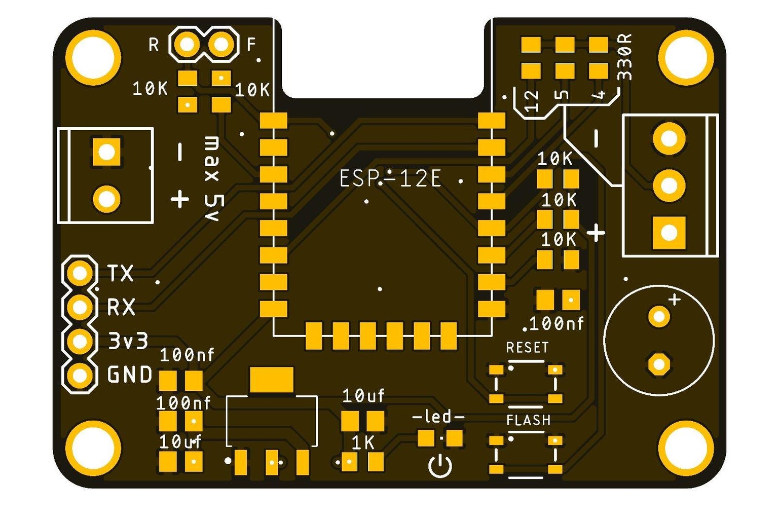


I designed a printed circuit board for those who want a professional prototype. This board is completely open source, if you want to get this printed circuit board easily, you can download the PCB Gerber file from the link below or order it directly. Thank you PCBWay for support and sponsorship in ordering the printed circuit board.
https://www.pcbway.com/project/shareproject/How_to_make_a_simple_wooden_wall_light.html
- Some SMD package type components were chosen for a compact design. The list of components used (Bill of Materials) is attached (see image 4).
- Solder paste is required to solder the components, injector type solder paste was used in the project (see image 5). Just drop a small amount of solder on the component pads. If you want, you can also order a stencil with the PCB. A PCB Stencil is a sheet of stainless steel with laser-cut openings used to place solder paste on a PCB board for surface mount component placement. The PCB stencil is used to deposit solder paste on designated places on a bare PCB board so that components can be placed and perfectly aligned on the board.
- After applying the solder paste, place the components according to the shared designator (see image 3 for component locations).
- There are 3 GPIO pins available on the board. The important point here is to solder the resistor to the pin output to be used for the LED. I chose the GPIO 12 pin (see image 6).
- Next, complete the soldering process of the SMD components using a hot plate tool. Miniware MHP30 Mini Hot Plate Preheater was used in the project.
- After completing the SMD component assembly, solder the required DIP components using a soldering iron (see images 9,10 and 11).
If your breadboard circuit or PCB board is ready, let's program it in the next step.
Step 8: Install the WLED to Breadboard Circuit


At this stage, we will use a tool called WLED to control the light project. You can use different ESP Web tools besides this app. The best part about WLED is that it requires no code, only plug and play!
- Connect the board to the PC
- Go to the WLED page (see image 1)
- Press the Install
- Select the port the board is connected to and wait for the installation to complete (see image 2 and 3)
- After the installation is complete, enter your Wi-Fi network information (see image 4 and 5)
Installation is that simple, now you can control your device. Click on "visit device" and start using your LED lighting by making the first settings mentioned below. (see image 6)
- Go to Settings, and set an address for easier access to the LED control panel, or use the specified IP address. (see image 7,8 and 9)
- Then you can access the LED control panel by entering the address in the web browser, or the application. (see image 10)
- Finally, enter the number of LEDs used and the GPIO pin number to which the LED is connected, and save. Also here, you can see the estimated current consumption according to the number of LEDs. (see image 11,12 and 13)
Now you can control the LED lighting in different scenarios with the WLED web browser, smartphone and tablet app. In the next and last step, how to install WLED for PCB will be shown.
Step 9: Install the WLED to Printed Circuit Board
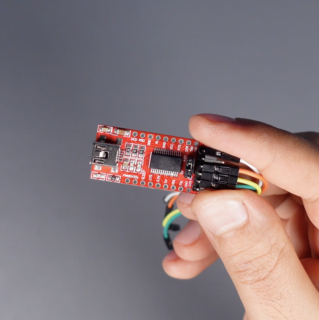
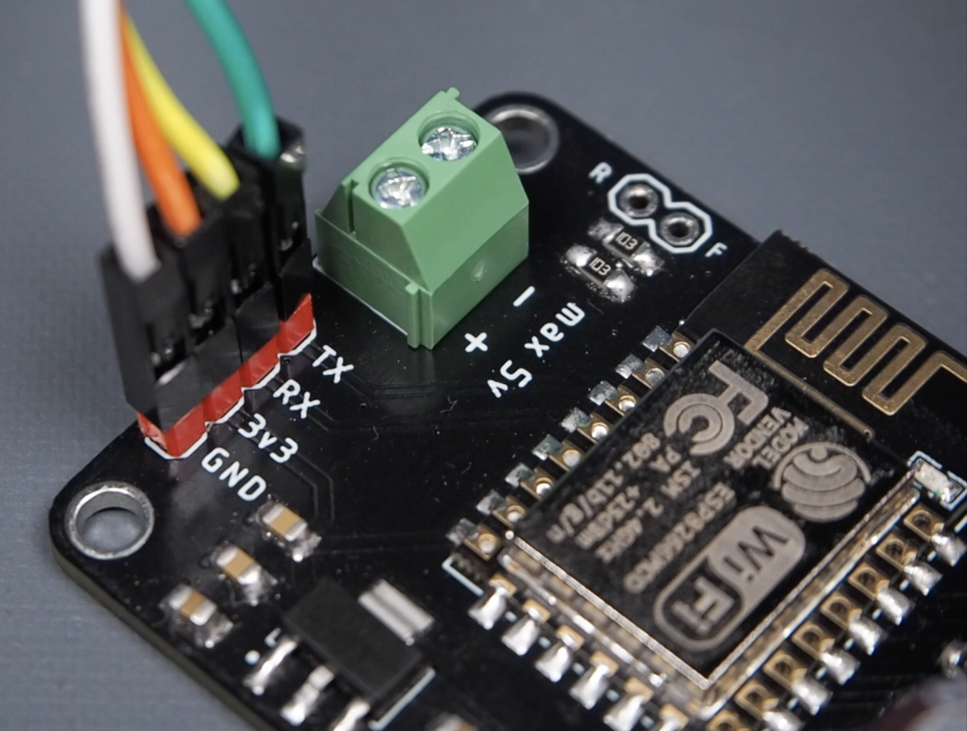
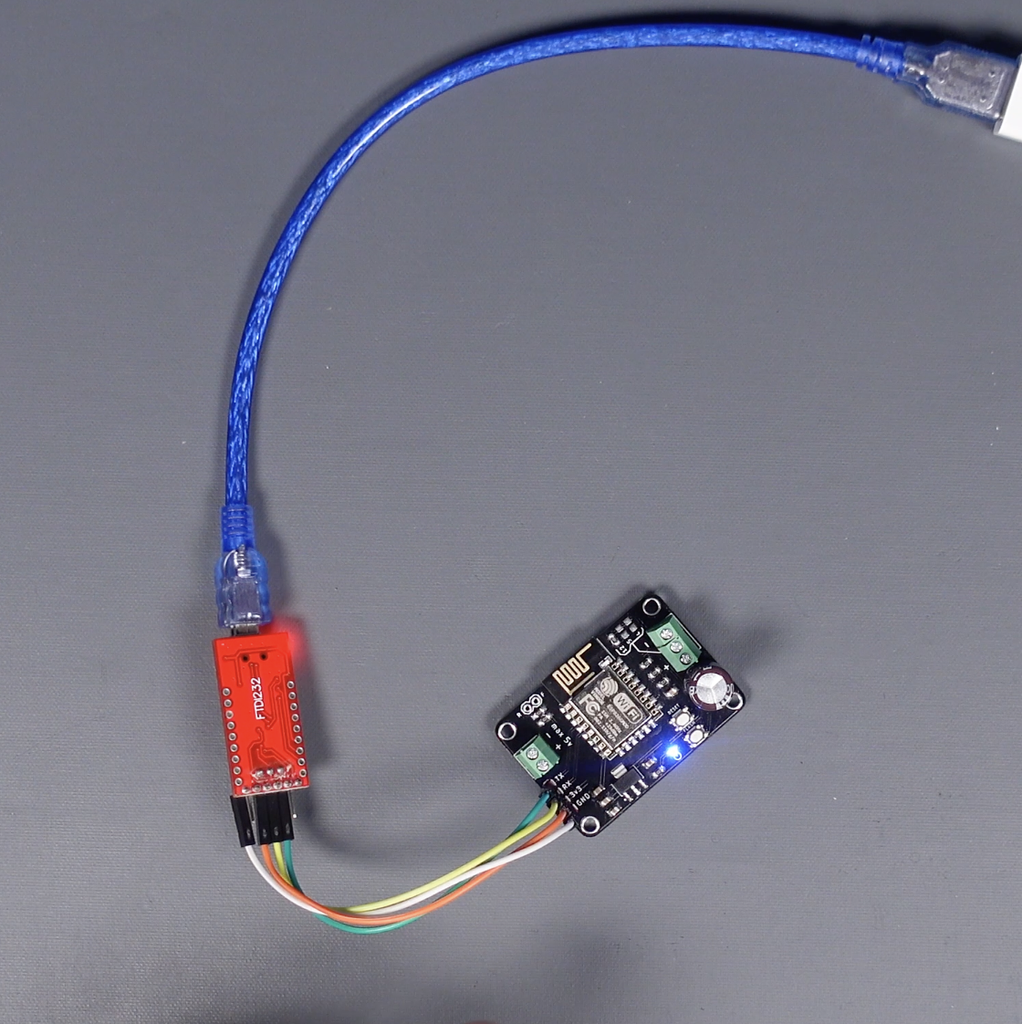
A firmware upload must be done when using the ESP for the first time. This process is simple, an "USB to TTL" module is used to communicate with the computer via USB.
- Make the connections of the module and the board as shown (see image 1,2 and 3) and connect it to the computer.
- Download the firmware programmer from GitHub https://github.com/nodemcu/nodemcu-flasher
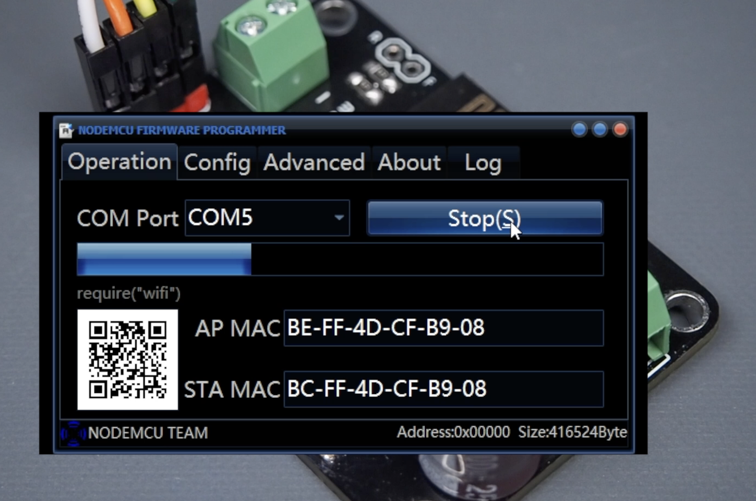
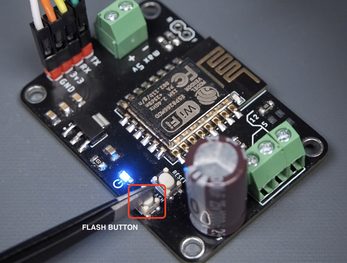
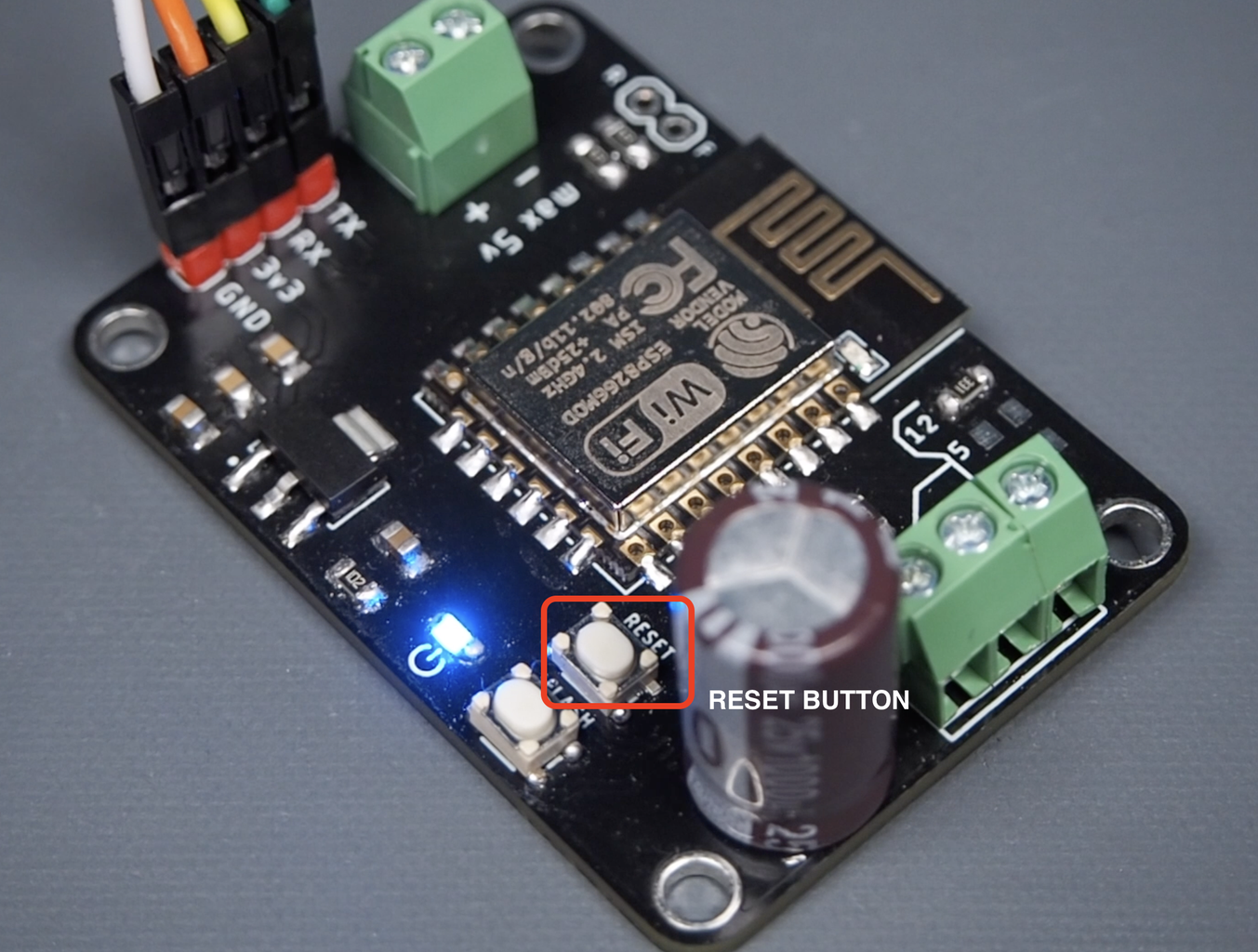
- Select the port the board is connected to and start the software installation while holding the flash button on the board. In the meantime, complete the software installation by pressing the reset button on the board once. (see image 4,5 and 6)
- Finally, prepare the board for LED control by following the WLED setup steps shown in the breadboard circuit.
The board works very stably without any problems. You can leave your opinions or questions in the comments, thanks for reading!

Participated in the
Anything Goes Contest


![Tim's Mechanical Spider Leg [LU9685-20CU]](https://content.instructables.com/FFB/5R4I/LVKZ6G6R/FFB5R4ILVKZ6G6R.png?auto=webp&crop=1.2%3A1&frame=1&width=306)


