

Introduction: DIY Solar Motion Sensor Security Light


Are you really concerned about safety in the surrounding areas of your house? If so, using solar-powered motion security lights can definitely help you!. You can get it easily in the market, but if you have a tight budget and curious to learn, then this project is definitely for you.
In this Instructable, I'll guide you on how to make a solar-powered motion sensor LED light by using cardboard, few LEDs and a cheap controller board.
The great advantage of this light is the combination of two of the most efficient and green technologies: LED and Solar. The light harvests solar energy during the day time and stores it in a Li-Ion battery for later use at night.
The sensor range is 2-5 meters with a sensing angle of 120°. when the motion detector is activated the light shines up to 25 seconds.
Supplies
Materials Used
1. Cardboard
2. Frosted Plastic Sheet ( Amazon )
3. Controller Board ( Aliexpress )
4. Solar Panel ( Amazon / Banggood )
5. 18650 Battery ( Amazon / Banggood )
6. Battery Holder ( Amazon / Banggood )
7. Strayhat LEDs ( Aliexpress )
8. Prototype Board ( Amazon / Banggood )
9. JST Connector ( Amazon / Banggood )
10. 22 AWG Wires ( Amazon / Banggood )
11. Heatshrink Tube ( Amazon / Banggood )
12. Pushbutton Cap ( Aliexpress )
Tools Used
1. Hot Glue Gun ( Amazon / Banggood )
2. Soldering Iron ( Amazon / Banggood )
3. Hot Air Blower ( Amazon / Banggood )
4. Wire Cutter ( Amazon / Banggood )
5. Wire Stripper ( Amazon / Banggood )
Step 1: How the Circuit Works?


The Schematic diagram is very simple. The heart of the circuit is a motion sensor controller board. The main components are as follows
1. Controller Board
2. LED Panel
3. Solar Panel
4. Li-Ion Battery
During the day time, the solar panel harvests solar energy from the Sun and stores it in a Li-Ion battery for later use at night. The onboard motion sensor activates only when movement is detected and gives the signal to turn on the LED panel. The LED panel is consists of 18 LEDs connected in parallel.

Step 2: LED Specifications
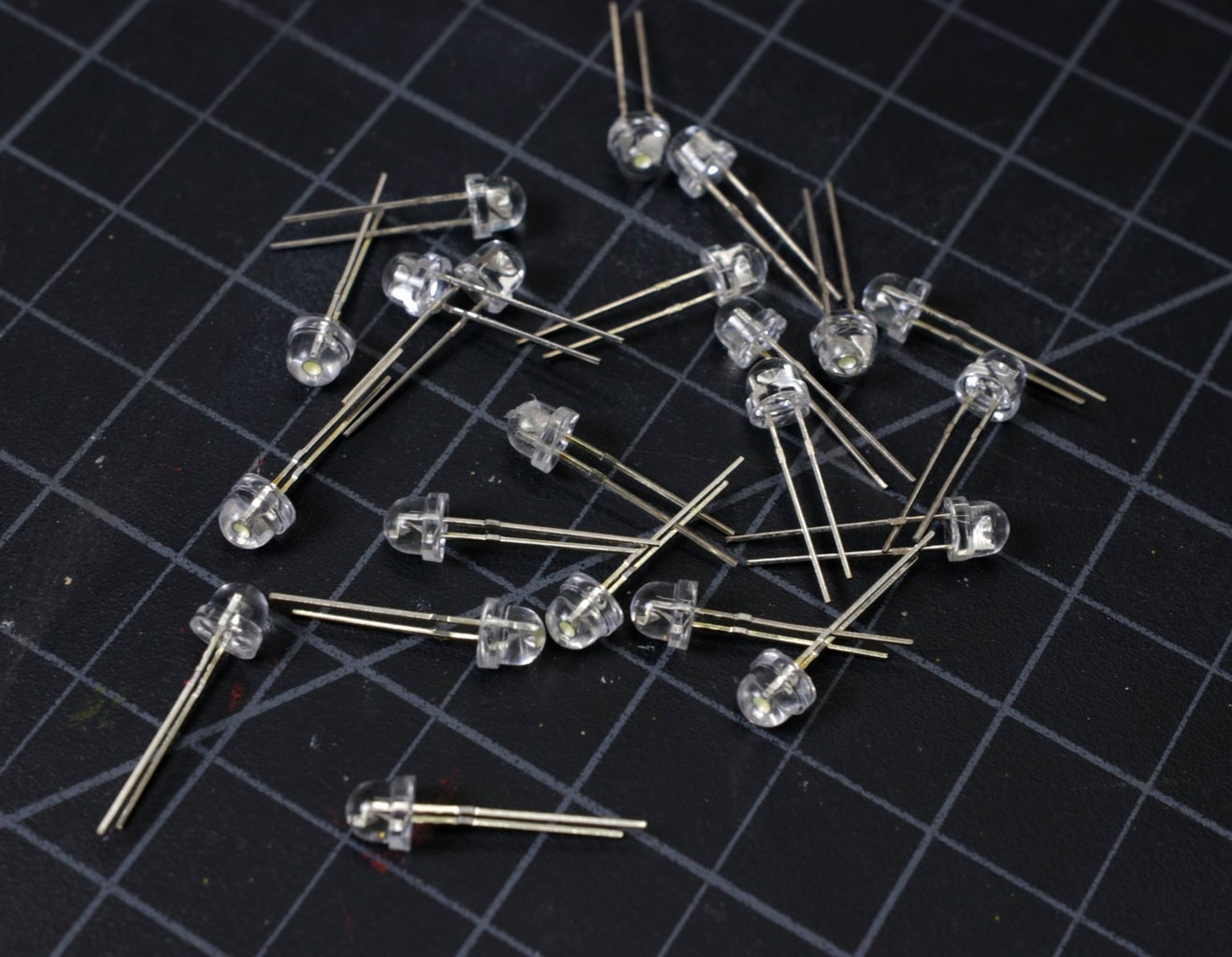


The LED used for making the LED panel has the following Specification:
1. Straw Hat 5 MM cold white LED
2. Forward Voltage ( Vf ) = 3.0 - 3.2 V
3. Maximum Continuous Current ( Ifm ) = 30 mA
4. Maximum Power Dissipation (Pm) = 80 mW
5. Luminous Intensity: 12000-14000mcd @ 20mA
6. Viewing Angle = 30 deg
You can see the attached datasheet for your reference.
Reference values considerations for designing the LED panel:
Forward voltage: 3.2 V
Forward current: 20 ma
Luminous Intensity: 13000mcd @ 20mA
Maximum Power = 80mW
Total Power Consumption and Lumens Output:
There are 18 Nos of LEDs are used in the LED panel.
Max Power Consumption = 18 x 80 mW = 1440 mW = 1.44 Watt
Luminous Intensity per LED = 13000 mcd @ 30 deg viewing angle
Lumen per LED = 10.94 Lm
I have used this calculator to convert mcd to Lumen.
Total Lumen = 18 x 10.94 = 196.92 Lm
By considering 25% loss, Lumen Output = 147.69Lm ( approx. 150 Lm)
Step 3: Making the LED Panel


I made the LED panel by using 18 Nos of 5mm Strayhat LEDs and a 3 x7 cm perforated board.
First, insert 6 LEDs in a row and bend the positive terminals at a right angle. Similarly, make 3 rows like the first one. Care shall be taken to maintain a uniform distance between the LED and row to row.
Then solder the LED legs and then join the legs together as per the schematic diagram.
Step 4: Add LED Panel Extension Wire


After making the LED panel, we have to connect two terminal wires to it.
Connect 22 AWG red wire to the positive and black wire to the negative terminal of the LED.
You can see the above picture for reference.
Step 5: Prepare the Battery Holder


The battery holder I have used comes with an extension wire. But the controller board battery terminal is female JST Connector instead of soldering pads. So we need a Male JST connector to connect the battery to the controller board.
Join the red wire of the Battery holder and JST connector together and then solder it. Do the same for the black wire.
To insulate the joint ( conductive part ), I have used heat-shrink tubing.
Step 6: Prepare the Solar Panel


First, apply a little amount of solder flux on the two soldering pads on the Solar panel.
Then apply sufficient amount of solder to cover the soldering pads.
Finally connects a red wire to the positive (+) terminal and black wire to the negative (-) terminal.
Step 7: Controller Board


The best thing about the Controller board is that it comes with the motion sensor. You don't need to buy a separate sensor for the project.
The connection terminals are properly labeled.The solar panel connections are ( S+ & S- ) , Light connections are ( L+ & L-) and battery connection is through a JST connector.
There are 3 different modes for the light, you can change it by pressing the pushbutton.
1. Faded / Full Bright
2. Full OFF / Full ON
3. Normal ON
Step 8: Making the Enclosure


I was thinking to make a 3D printed enclosure but unfortunately, my 3D printer is not working now.
But I could not resist my idea in the head to come in to live, so decided to make the prototype by using some cardboard.
I cut the cardboard box received from Amazon Shipment to make different panels. The entire enclosure has the following panels:
1. Back Panel - rectangular- 14 x 7 CM
2.Front Panel for LEDs - rectangular- 14 x 8 CM
3. Top Panel for Solar Panel- rectangular- 14 x 7 CM
4. Two Side Panels- triangular- 11 x 8.5 x 7 CM
Cut the above panels as per the dimensions are given above. I used my Exacto knife to cut out all the panels.
The front panel have the following slots:
1. LED panel
2. Motion Sensor and Push Button
The top panel have two holes to pass the solar panel wires.
Step 9: Make LED Diffuser

The light coming from the LED panel creates strain to the naked eye, so LED diffuser is required for more consistent and pleasing light. You can buy an LED diffuser plastic sheet or acrylic sheet.
In my case I made it from an iPad Cover plastic, it works with charm.
The size of the diffuser is 3.5 x 7 CM.
Step 10: Mount the Components


First I glue the battery holder to the back panel.
Then glue the diffuser sheet over the led slot. After that glue two small strips of cardboard on both sides of the slot which will act as the base for the LED panel. Place the LED panel over the base and hot glue over it. Similarly, install the Controller board by properly aligning it.
Pass the Solar panel wire through the two holes on the top panel and then glue it.
Step 11: Assembling All Panels


Align the back panel, front, and top panels, then apply some masking tape to hold them temporarily.
Apply a sufficient amount of hot glue at the panel joints.
Fold the panels and hold for few moments until the glue dries out. Then apply glue at the top joint as shown above.
At last cover the both sides by using the two side panels.
I stick an Instructables sticker on the front panel that I was received from an Instructable prize pack.
Step 12: Mounting Arrangement


To mount the light on the wall surface, I have used double-sided tape.
Cut two strips of double-sided tape and stick on the back panel.
You can see the above picture, for clear understanding.
Step 13: Testing & Conclusion
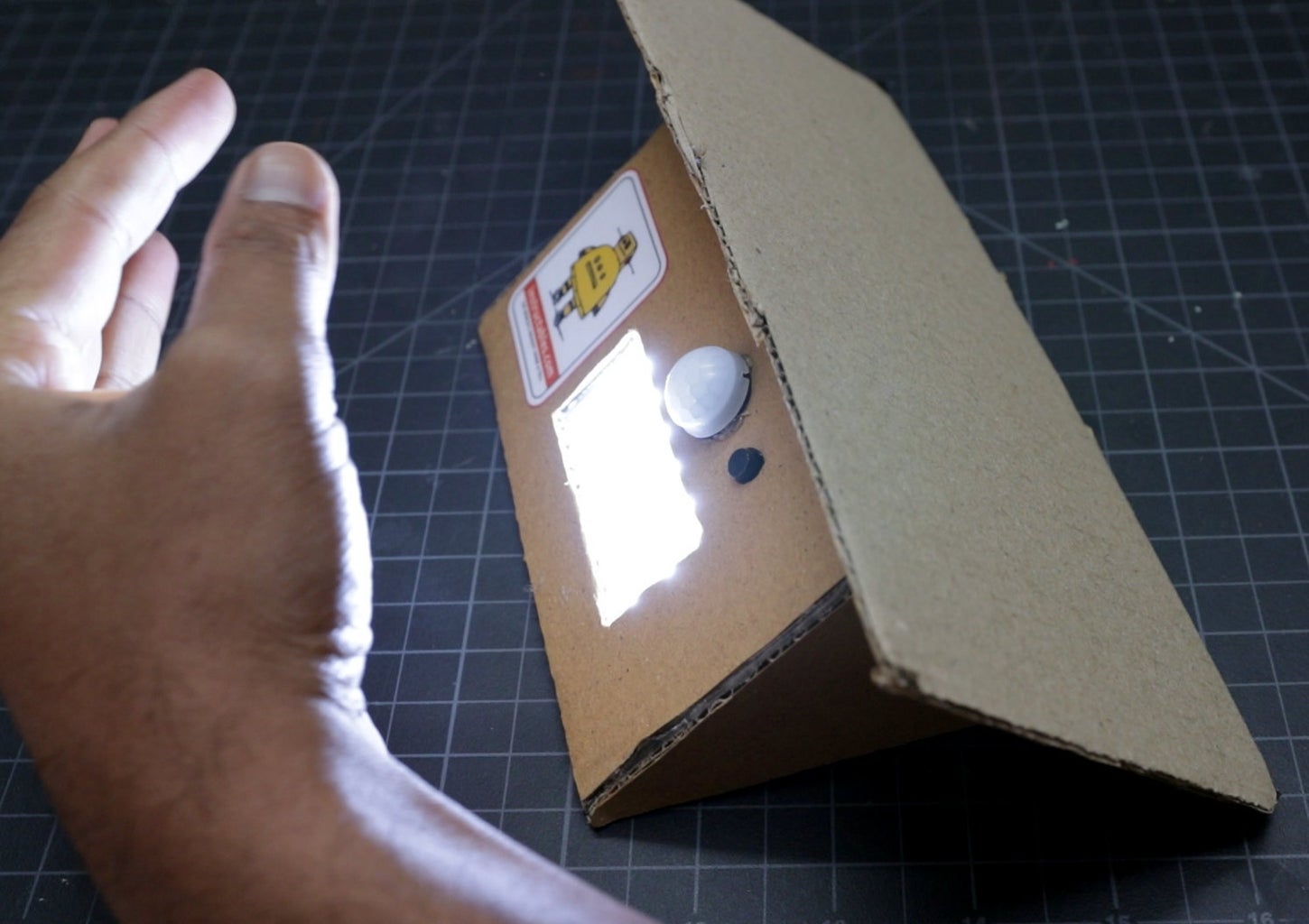

The building of the Motion Sensor light is complete. Now it is time to test it and put it into service.
To test the light, cover the solar panel by using any dark material like cardboard or your palm. The led panel will lit up with half brightness. If any motion is detected in front of the sensor, the led will glow with full brightness. You can change the mode by pressing the pushbutton.
I hope you have enjoyed my project. If you like this, don't forget to share it.
This Instructables is entered into Reuse Contest, please vote for me.
Thank You!

Participated in the
Reuse Contest


