

Introduction: Delta Plotter


This instructable describes how to build a delta-style “parallel” plotter using an Arduino UNO R3, three NEMA17 stepping motors, some push-rods, and 12 magnets. [1]
The plotter features:
- a 3D workspace which allows it to mimic a 2D plotter
- a 100mm x 100mm print area [2]
- 0.2mm resolution (approx.)
- high speed
- an on-board g-code interpreter. All that is required is an XON / XOFF terminal that can send text-files one line at a time.
Construction is simple ... all you need is a hacksaw, a hammer, a round-file, a few drills, and a screw-driver.
The estimated cost to build this plotter is less than $100 USD
Photos
- The video shows the plotter in action.
- The cover photo shows the completed plotter
- Photo 2 shows the sample plot created in the attached video. [3]
Notes
[1]
The plotter is purely experimental and is published in the hope that the design notes will be of use to someone. Any construction defects affect the plot accuracy.
[2]
The plotter dimensions may be scaled to produce a larger print area.
[3]
The trapezoid suggests that the arm positions need adjusting. I’m not certain about the wobbles ... gearing would probably help as each motor is only moving a small amount.
Step 1: Circuit Diagram


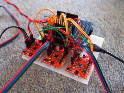
The delta plotter circuit diagram is shown in photo 1.
A matching shield is shown in photo 2.
Photo 3 shows each of the three Big EasyDriver circuit boards mounted on a scrap of sheet plastic.
The Big EasyDrivers expect the wires from each motor winding to be adjacent. You may need to swap the two center wires of each motor cable to achieve this. You will see that I have done this in photo 3 ... the cable wire colors from the motor are red, blue, green, black ... whereas the socket colors are red, green, blue, black
Adjusting the motor current(s):
Step 1
- Switch off then unplug two of the motors.
- Rotate each of the Big EasyDriver potentiometers fully clockwise (minimum current position)
Step 2
- Switch on and adjust the small potentiometer on the Big EasyDriver module for a current reading of 0.4 amps (400mA).
Step 3
- Repeat this process for the remaining two motors and Big EasyDriver modules.
Step 2: Parts List

The following parts were obtained from https://www.aliexpress.com:
- 3 only NEMA17 “17HS3430” stepper motors, 400mA, 30 ohm, 1.8 degree, 4wires, 2800g.cm
- 3 only NEMA17 mounting brackets for the above motors.
- 3 only GT2 20 tooth timing pulley, aluminum, bore 5mm, width 6mm
- 3 only “Big Easy Driver Board V1.2 A4988 Stepper Motor Driver Board 2A/Phase
- One set diagonal push rods, L200 Rods Arms Kit + Magnetic Ball Joint + Steel Ball for Kossel 3D Printer
- 1 only “Arduino UNO R3 + USB cable
- 1 only Arduino Prototype PCB Shield Board
- 6 only Arduino male-to-female jumper cables
- 3 only Arduino male-to-male jumper cables
The following items were obtained locally:
- 1 only 1N5404 diode
- 1 only SPST switch
- 1 only PCB mount screw terminal (5mm) for connecting the battery/external power
- 1 only 20mm x 3mm length of aluminium extrusion
- 2 only M6 x 32mm washers
- 3 only M3 x 25mm tapped metal spacers
- 6 only M3 x 5mm bolts
- 6 only M3 x 10mm nuts and bolts
- 12 only M4 x 15mm nuts, bolts, and washers
Miscellaneous items:
- 1 only ball-point pen spring
- 1 only radio knob with brass center
- hook-up wire
- scrap of 18 gauge aluminium sheet metal
- small piece of tinned-steel from the bottom of a paint tin
The estimated cost of this project is less than $100 USD
Warning
This magnets in this project are extremely powerful and could affect a pacemaker if brought close to your body.
The magnets are also extremely brittle and will shatter if subjected to sudden shock such as attracting one piece to another from a distance (photo 1).
Step 3: Theory


Mechanical
The design is a variation of the “Delta Robot” that was invented in the early 1980s by professor Reymond Clavel at the École Polytechnique Fédérale de Lausanne in Switzerland. [1]
Photo 1 shows one of three motors, and the arm positions for each, when the pen is located at XYZ coordinate (0,0,0).
Each motor is mounted on a common base of radius “Rb”. The angle between each motor is 120 degrees. This forms an equilateral triangle ... hence the name “Delta”. (photo 2)
Attached to each motor is a lever “A” and two pushrods “B”. Each set of push-rods is attached to an end-effector (platform) of radius “Re”. This platform supports the pen.
The push-rods have steel ball-joints at each end which means they can swivel in all directions. Strong concave magnets hold each push-rod in place.
The push-rods are also arranged in sets of two ... the resulting parallelograms keep the edges of the end-effector parallel to the drawing surface and prevents it from twisting.
Operation
The absolute pen position is determined by varying the angle of each motor-arm:
- the pen is raised if all motor-arms move outwards
- the pen in photo 1 will move to the right if we simultaneously move arm “A” outwards and the two remaining arms inwards.
- other directions are possible by moving two arms outwards/inwards and moving the remaining arm inwards/outwards
Mathematics
My equations for calculating ”angle1” are shown in photo 3. [2]
Three sets of XYZ coordinates are also required ... one for each motor. These coordinates are obtained using the following rotational matrix formulas: [3]
x1 = x*cos(angle) + y*sin(angle) ................................................................ (1)
y1 = y*cos(angle) – x*sin(angle) ................................................................ (2)
Where “angle” is the angle of the XY plane for that motor relative to the actual X axis.
Notes
[1]
US patent No. 4,976,582
[2]
All calculations have been translated to the XY “shadow-plane” for that motor as this is the only plane in which lever “A” can rotate. The “s” suffix (As, Bs, Cs) in photo 1 indicates “shadow”.
Complex mathematics are not required ... just the Cosine formula and Pythagoras.
Keep in mind that the each corner of the “wire-frame” is 90 degrees.
[3]
Step 4: Pen Holder


The pen-holder was fashioned from two M6 x 32mm washers, three M3 x 25mm tapped metal spacers, a radio knob, and the spring from a ball-point pen.
Construction
Construction details are shown in photos 1 and 2:
Step 1
- Drill three evenly spaced 3mm holes through each of the washers (photo 1)
Step 2
- Attach the M3 x 25mm tapped spacers (photo 1 and photo 2).
Step 3
- Enlarge the center hole of each washer with a round-file such that the pencil slides freely without wobbling (photo 1 and photo 2).
Step 4
- Drill the brass center of a “radio knob” to form a loose fit around the pencil. The grub-screw determines how far the pencil protrudes below the holder (photo 1 and photo 2).
Step 5
- Rewind the spring from a ball-point pen to form a loose fit around the pencil. The spring ensures that the pencil tip maintains contact with the drawing surface. It also prevents the pencil lead from breaking when the end-effector is driven downwards (photo 1 and photo 2).
Step 5: End Effector


Photos1 and photo 2 show the completed end-effector.
The pen-holder is attached to two discs ... one plastic ... one tinned-steel.
The concave magnets are held in place by magnetic-attraction to the tinned-steel plate
The 12mm diameter holes in the plastic disc prevent the magnets from sliding about.
Photo 3 shows the drilling template.
Construction
Step 1
- Apply masking tape to both sides of a piece of scrap plastic. This provides a writing surface when marking out the disc. It also prevents the plastic from splintering when drilled.
- Draw two concentric circles ... 32mm diameter ... and 64mm diameter.
- Drill a 4mm hole through the center (photo 4).
Step 2
- Drill a 4mm hole 32mm in from the edge of a “saw-horse”. Place a 4mm bolt through the plastic into the 4mm hole in the “saw-horse”. Now spin the plastic as you cut it with a fine-tooth saw (photo 4).
- After one revolution you will have cut a perfect circle (photo 5 and photo 6).
Step 3
- Mark out where to drill. All of the large holes are 12mm which is a snug fit for the magnets. All of the small holes are 3mm (photo 7).
- When drilling the small holes use the base of the pen-holder as a template.
- Start each of the large holes with a pilot drill followed by a 6mm drill. Use a small round file (or taper-reamer) to enlarge the holes to 12mm. Plastic is brittle and is likely to break if you use a large drill.
Step 4
- Cut a 64mm diameter disc from tinned-steel (I used the bottom of an old paint can).
- Use the plastic magnet holder as a drilling template.
- The end-effector is now ready for assembly (photo 8).
Step 6: The Motor Arms


The “A” motor arms are made from a length of 20mm x 3mm aluminium
extrusion.
Modified GT2-20 pulleys are used to attach each arm to the motor shaft.
Construction
Step 1
- Cut three 120mm lengths of aluminium extrusion.
- Drill a 3mm hole 10mm in from each end ... the hole spacing is 100mm
Step 2
- Remove the end rims from three GT2-20 pulleys using a hacksaw (photo 1)
Step 3
- Enlarge one of the holes in the aluminium extrusion until the pulley almost fits (photo 1). I used a 6mm drill followed by a taper-reamer but a round-file will work equally well.
Step 4
- Use a vice to press the modified pulley into the slightly undersize hole. This forms a friction fit. (photo 2)
Step 5
- Drill an oversize hole in a block of wood. Place the pulley over this hole and drive it fully home ... I used a hammer. (photo 3)
Step 6
- Lock the pulley in place with four evenly placed center-punch marks. The punch marks deform the aluminium bar into the gaps between the pulley teeth ensuring that it won’t slip. (photo 4)
Step 7
- Attach the arms to the motors (photo 5)
Step 7: Motor-arm “Push-rod” Attachments

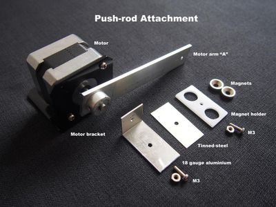


Each motor-arm requires a specially shaped attachment for connecting the pushrods. This attachment comprises thee sections:
- a 60mm x 20mm 18 gauge aluminium plate folded 20mm from one end to form an L-section.
- a 20mm x 40mm tinned-steel plate that is sandwiched between the aluminium L-section and a plastic magnet-holder. The tinned-steel plate holds the magnets in place and was cut from the bottom of an old paint can.
- a 20mm x 40mm plastic magnet-holder made from scrap plastic. The magnet holder prevents the magnets from sliding around.
Photos
- Photo 1 shows the basic drilling template for the plastic magnet-holder. When assembled the push-rods must form a parallelogram. To achieve this the center-to-center hole spacing for the magnet-holder must be the same as your end-effector hole spacing. Mine was exactly 24mm ... yours may be different.
- Photo 2 shows each of the three sections before assembly.
- Photo 3 shows how the attachment is connected to the motor-arm. Note that the L-shaped bracket goes over the arm. This locks the attachment in position.
- Photo 4 shows the other side of the motor-arm
- Photo 5 shows how motor-arm “A” is connected to the end-effector via the push-rods “B”. Note how the push-rods form a parallelogram.
Step 8: The Base

The base is constructed from a 500mm x 500mm x 6mm composition board.
The motors are attached as shown in photo 1 with each magnet-holder centered over the construction lines.
The construction lines for each motor are identical except that each adjacent motor is rotated by 120 degrees.
Step 9: The Push-rods


The “B” push-rods and magnetic bearings were obtained from https://www.aliexpress.com/ and require no modification. These push-rods are accessories for a different style printer but work well in this design.
Each pushrod comprises five parts (photo 1):
- 2 only steel balls with M4 tapped holes
- 2 only M4 grub-screws
- 1 only 200mm carbon fibre tube
Assembly
Step 1
- Screw an M4 grub-screw into each steel ball until it is finger-tight.
Step 2
- Apply expoxy resin to the exposed tips of the M4 grub-screws and push them into the open ends of the carbon-fibre tubes. Lie the tubes flat while the epoxy resin dries.
Step 3
- Loosen one steel ball on each tube while the epoxy is “plastic”. This allows you to adjust the rod lengths if necessary. Let the epoxy set.
Step 4
- The push rods may now be attached to the end-effector (photo 2).
Step 5
- Adjust the rod lengths to suit by loosening a ball on each arm slightly until the pencil is upright. Use a spot of epoxy or hot-glue to fix the balls in place.
Step 6
- Label each rod in case you dismantle the plotter for storage.
Step 10: Software

Upload the contents of the attached file, “delta_plotter.ino”, to your Arduino.
Launch “Serial Monitor” and set the baud speed to 115200 ... the menu in photo 1 should appear. If the menu fails to appear type “menu”.
Apply 12 volts to the motors and type “t1” ... the pen should raise. Type “t2” and the pen will lower. “T3” will draw a square with diagonals.
The interpreter :
- is not case sensitive.
- contains useful code, such as arc routines, from my earlier plotters
- The g-code interpreter features sticky keys ... there is no need to enter data unless the data has changed.
Example:
- G00 X0 Y50 will move the pen 50mm upwards
- G00 X50 will move the pen sideways from coordinate (0,50) to coordinate (50,50).
Attachments

Step 11: Summary
The plotter is purely experimental and is published in the hope that the design notes will be of use to someone.
The print area for this plotter is 100mm x 100mm ... about the length of motor-arm "A"
The plotter dimensions may be scaled to produce a larger print area.
Each motor only moves part of a revolution. A gear-box would improve the resolution and increase the motor torque at the expense of speed.
Any construction defects distort the plots
A simple g-code interpreter has been included.
Click here to view my other instructables.

Second Prize in the
Magnets Challenge


