

Introduction: Design and Build Your Own 3D Printed RC Plane


Hey everyone, I'm excited to take you on a wild ride through my journey designing and building a 3D printed RC plane. This isn't your typical how-to guide. Think of it as a build log infused with my ups, downs, and valuable lessons learned.
Whether you're an experienced pilot or just starting out, this guide is for you. While some experience in RC planes and 3D printing helps, I'm here to help you regardless of your expertise. (I love replying to your questions in the comments!)
What You'll Discover:
In this tutorial, I'll break down the entire process step by step, from designing the fuselage, wings, V-tails, canopy, and motor cover, to 3D printing these components, assembling your plane, and finally, launching it into the sky.
The Build Log Chronicles:
But here's where it gets interesting. I'm not just sharing the flawless path to success. I'll be honest about the hiccups, the crashes, and the mistakes. For example, to save some bucks and avoid a costly 3D printed wing, I initially experimented with foam. And yes, there were crashes, but each one taught me something valuable.
I am Prithul, currently an engineering exchange student at the Fox Valley Tech Appleton, WI, and this was my last 3D printing project before leaving my home country Bangladesh. Ready to build one yourself? Let's take off!
Supplies


Before we dive into the design and building process, let's make sure we have everything we need to get started. Here's a list of the essential materials and tools you'll want to have on hand:
Materials:
- PLA Filament: Choose a PLA filament that prints best on your 3D printer. PLA+ is a good choice for its added strength and affordability. I used SUNLU PLA+ filaments but there are some light-weight PLA filaments that might work better for their, well, light weight. My plane used only around 342 grams of filament so a 1KG spool should be enough for you.
- Electronics Components: These may include
- 1200-2200kv Brushless Motor. I used a Turnigy D3530 1100kv motor.
- An Electronic speed controller (ESC) suitable for your motor. I used a generic 40A ESC.
- LiPo battery: I suggest using 3S 1500-2200mAH batteries.
- Transmitter and receiver: I used a Flysky FS-i6
- 3x 9g servos. Any generic servos would work but metal gear ones last longer.
- Screws and Fasteners: You will need a few M3 screws and nuts to mount the motor and locked the carbon rod to the fuselage and V-tail.
- Carbon rod: You can find these at your local hobby shop or online ones like HobbyKing. You will need:
- 600mm long - 16mm carbon rod. This rod helps us save a lot of weight and connects the tail to the fuselage.
- 1200mm long - 3mm or 4mm carbon rod for wing spur.
- Control Linkages: Thin wires or pushrods for connecting servos to control surfaces.
Tools:
- 3D Printer: You'll need access to a 3D printer with a bed size of at least 200x200x200
- Fusion 360 Software: This computer-aided design (CAD) software will be your primary tool for designing your RC plane.
- Calipers: A good set of digital calipers is greatly helpful for taking measurements of the motor, battery, and other electronics that fit into the 3D design.
- Screwdrivers and Allen Keys
- Soldering Iron (may not be necessary)
- Super glue: To join the 3D printed parts. Additionally, a spray super glue activator will save you some time.
- Safety Gear: Don't forget safety glasses, hand gloves, and a well-ventilated workspace, especially when you're gluing the parts together.
That's it! As you progress through the steps, you may find additional tools or materials are needed for specific tasks.
Step 1: Planning Your RC Plane

Before we jump into the designing, let's take a moment to plan our RC plane. This crucial step will help you define your project's direction and ensure a successful build.
1. Decide on the Type of RC Plane:
- Consider whether you want to build a trainer plane, a sporty aerobatic model, a war plane, a glider, or something entirely unique.
- Think about your flying preferences and skill level.
- You might want to take some time to think of the different styles of tail you can have like traditional inverted T-tail, T-tail, or a V-tail which I went with.
- I went with a glider since they usually need less structural strength, and are easier to fly at slower speeds.
2. Wing Shape and Airfoil Selection:
- Choose a wing shape (e.g., straight, swept, delta) that suits your plane's intended purpose.
- Research and select an airfoil profile optimized for your chosen flying style. You can find pretty much any airfoil shape on http://airfoiltools.com/
- I went with the classic NACA 2414 for the added thickness in the middle. It's also just a good airfoil for gliders in my experience.
3. Determine Wing Size:
- I find it easiest to calculate all the wing part sizes if I start from the wingspan.
- Calculate the wingspan based on your chosen type of plane and intended flight characteristics. A larger wingspan airplane will generally fly more efficiently and will be able to fly slower for the added lift. But remember, filament cost goes up dramatically as you scale up your plane.
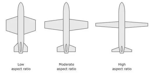
- Pick an aspect ratio for your wing span and chord (length vs width). A glider may typically have a wingspan of 9-10 times the chord.
- I decided to build a 1200mm wingspan glider (although I increased it to 1400mm later) and 128mm wing chord.
4. Calculate Fuselage and Tail Size:
- Use your chosen wing size as a reference to calculate the appropriate length and dimensions of the fuselage and tail sections. Check the attached photo to get an idea of the aspect ratio of each part of the plane based on the wingspan.
5. Additional Resources:
- For detailed guidance on wing shapes, airfoils, and size calculations, you can refer to these tutorials or resources:
- https://rcplanes.online/design.htm (photo used from this site for this step)
- https://www.flitetest.com/articles/what-if-i-want-to-design-an-airplane
By taking the time to plan your RC plane's characteristics and specifications, you'll be making sure the plane will actually generate lift and fly.
Step 2: Designing the Fuselage


Designing the fuselage is a pivotal step in creating your 3D printed RC plane. Follow these steps to ensure a sturdy, well-fitting fuselage that accommodates your electronics and maintains balance.
1. Import Airfoil Drawing:
- Begin by importing the airfoil drawing you've selected into Fusion 360. This will serve as the foundation for your fuselage design.
- Here's a quick video showing how you can import airfoil DAT files into Fusion 360: https://www.youtube.com/watch?v=3Huj4tK-V3U
2. Create a Solid Fuselage body:
- Using the dimensions calculated for your fuselage, sketch and extrude a solid shape of your fuselage.
- Ensure there's ample space for your battery and electronic components.
- Add any fancy curve you like. Some people like to make their fuselage look like real airplanes with a raised canopy.
- I went with a simple round shape to ensure least amount of drag and ease of printing.
3. Cut Out Wing Airfoil:
- Cut out the airfoil sketch from your solid fuselage shape. This is where the wing will be inserted.
- You might want to leave a tab at the front of your wing so that it is somewhat held in place by the fuselage itself.
4. Hollow Out the Fuselage:
- Utilize the "Shell" command to hollow out the fuselage, leaving a wall thickness of around 0.84mm.
- The 0.84mm wall thickness ensures that two lines of walls will be printed for added durability. More about this when we get to printing the model.
5. Design the Canopy:
- Carve out a space within the hollowed fuselage for the canopy. Ensure that it's large enough to insert the battery and electronics without obstruction.
- Using some surface modeling technique in Fusion 360 is useful for this part: https://www.youtube.com/watch?v=NypRE2aFhh4
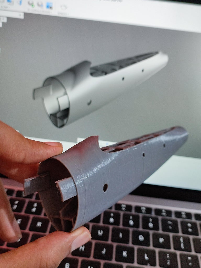
6. Add a Cylinder and Screw Holes for the rod to enter:
- Include a cylinder within the fuselage for mounting the 16mm carbon rod.
- Add precise screw holes to grab onto the sides of the carbon rod. You may also drill holes into the rod to securely keep it mounted to the fuselage.
7. Motor Mount:
- At the front of the fuselage, ensure that you have a motor mount plate/surface to accommodate your chosen motor.
- You can simply google the dimensions for your motor mount and add the holes accordingly.
- I added a hole near the motor to let some of the upcoming air into the fuselage. Additional holes were added in the back for the air to escape.
8. Strengthen with Internal Ridges:
- Enhance the internal structure by adding supporting ridges across the interior of the fuselage. These will add strength and stability. Here's a cool way to do it: https://www.youtube.com/watch?v=pxm-CJLZ0nI
9. Halve the Fuselage for 3D Printing:
- For ease of 3D printing without the need for excessive support structures and bed adhesion, divide the fuselage into two or more halves that can be printed separately and then assembled.
- We will print the fuselage upright as it is very long and hard to print laying down on the bed. Good layer adhesion is important for all of these prints as we print them upright.
- My fuselage was slightly taller than my 3D printer's Z height so I made it into two parts.
Pro tips:
- It's always a good idea to create a dummy model of your motor, battery, and receiver with correct dimensions to ensure they will fit into the fuselage. Try not to get the dimensions of your battery wrong while converting inches into millimeters like I did *oops*
- Don't divide the fuselage right where you think the weakest point might be. The joints are most prone to breaking on rough landings. It takes some guess work but try to have the joint where there are additional support from the canopy or wing.
- Throughout this process, precision and careful consideration of component placement are key. Remember that the fuselage is not just a housing; it plays a vital role in the aerodynamics and it will take the most hit on landings. Keep strength in mind but balance the strength and weight.

Step 3: Designing the Wing


Personal Experience:
Before we dive into creating the wings, let me share a bit from my own journey. Initially, I opted for a foam wing while using a 3D printed fuselage and V-tail. It was a slow start, as I wasn't entirely sure if a fully 3D printed plane would fly without being too heavy. But sometimes in this hobby, curiosity leads to great discoveries. The 3D printed fuselage and V-tail performed remarkably well, which gave me the confidence to go ahead and design the 3D printed wing. It was a leap of faith, and it paid off. (It did crash and break the fuselage once giving me more ideas on the weak-points of my fuselage)
Now, let's get into the details of designing your wings.
1. Transform Airfoil Sketch:
- Start with the airfoil sketch from your previous calculations. Extrude or loft it to create a solid shape.
- You may want to adjust the size and consider using a smaller airfoil at the tip to create a tapered wing.
2. Design Winglets or Wingtips (Optional):
- For enhanced aerodynamics and style, you can design winglets or wingtips. Winglets help the wing generate lift more efficiently by reducing drags at the tip of the wing. And also, it just makes your plane look nicer.
- Here's a tutorial on drawing winglets that helped me greatly: https://www.youtube.com/watch?v=vKvwNYWbSNc
3. Create Custom Infill for Lightweight Strength (Tutorial Attached):
- Design an artificial infill pattern that optimizes strength while keeping the wing as light as possible. Tom Stanton posted a great tutorial on this: https://www.youtube.com/watch?v=QJjhMan6T_E
4. Add Holes for Carbon Wing Spars:
- Incorporate holes in the wing design to insert carbon tubes for added structural integrity and stability.
- The hole should be added at the thickest part of the wing body to ensure the maximum amount of weight is distributed into the carbon wing spars.
5. Cut Out Servo Holes:
- Carve out spaces for servo installation, ensuring a snug fit for precise control.
6. Cut out Ailerons:
- Cut out ailerons from the wing design. This is done by drawing lines where you want to cut the aileron, and extrude a thin wall cutting the aileron separate from the wing.
- Depending on your preference, you can use one servo to control two long ailerons or opt for two servos and two shorter ailerons for more precise control.
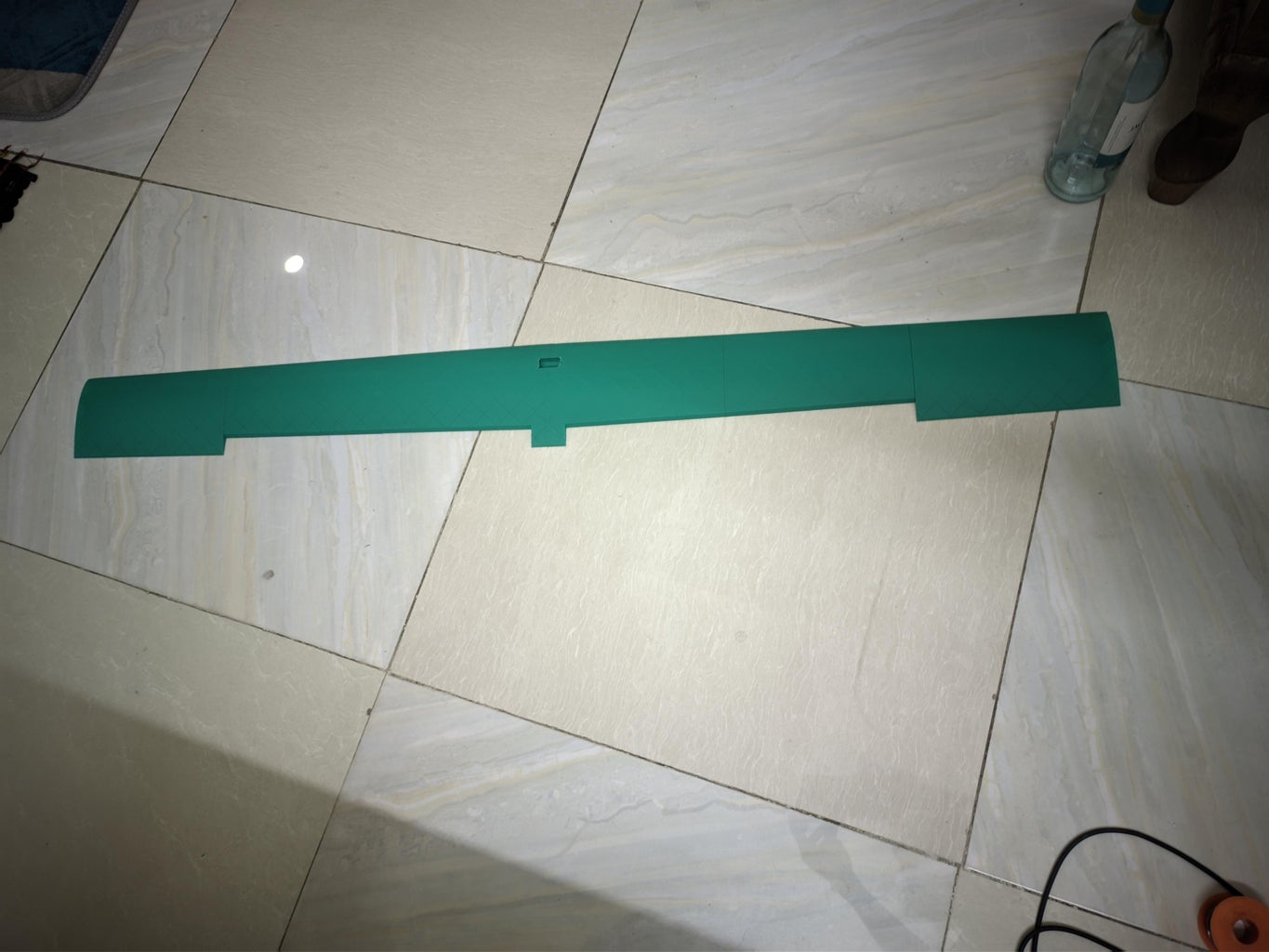
7. Splitting into Printable Pieces:
- To accommodate 3D printing, divide the wing into printable pieces. I needed six pieces, three on each side. This step simplifies the printing process.
- You may try to avoid supports for the winglet by cutting the last pieces at the tip of the wing at an angle. A smooth surface is really necessary for efficient flying.
Pro Tip: Adding some extra surface area where the printed parts are glued together helps super glue create a stronger joint. Additionally, experiment with different infill angles that your printer can handle; a 45-degree angle is a good starting point.
With these steps, you're well on your way to crafting a set of wings that will complement your 3D printed RC plane perfectly. The combination of strength, weight optimization, and precise design will be essential for successful flights.
Step 4: Designing the V-Tail


Creating well-balanced and aerodynamic V-tails for your RC plane is essential for a stable flight. Follow the following steps to design your V-tails. Carefully watch the animated GIF attached above to get a gist of the whole designing process.
1. Drawing the guides:
- Start by sketching a line at the desired V-tail angle. In my case, I wanted the tail to be at a 38 degree angle from the horizon. The length of the line should be your tail length.
- Draw a perpendicular line at the bottom and tip of the line.
- Draw plains across the perpendicular lines, you will have your airfoils imported into sketches on these plains.
2. Create Airfoil Drawing:
- Use the selected airfoil and dimensions calculated in the previous step to create an accurate drawing of the V-tail airfoil on the generated plains.
- You can have two different sized airfoils, preferably with a shorter chord at the tip.
- Ensure the correct dimensions or chord of airfoils for your design.
3. Loft your airfoils:
- Loft the two airfoils, now you have one side of the tail body!
- Optionally, add rounded wingtips for enhanced aerodynamics
- For detailed instructions on creating rounded wingtips, watch this video: https://www.youtube.com/watch?v=gteg9oqZemY
4. Cut Out Elevator/Rudders:
- Cut out the elevator/rudder sections, making sure to create a 45-degree cut to allow for hinge movement, enabling the control surfaces to move up and down.
- Again, follow the dimensions guideline to ensure the control surfaces are big enough.
5. Create Custom Infill:
- Add thin cuts in the model to create your custom infill pattern.
- The procedure to create tail infill is the same as the wing infill design process in the previous step. (https://www.youtube.com/watch?v=QJjhMan6T_E)
6. Servo Placement:
- Add a hole in the V-tail to insert and securely glue the servo in place. This will save us a lot of air drag as the servo integrates into the body.
- Ensure the servo placement aligns with your control rod. I personally prefer not designing the control horn into the 3D print, and instead gluing on some custom 3D printed control horn later. https://www.thingiverse.com/thing:781066
7. Mirror the Design:
- Duplicate and mirror the entire V-tail design to create the other side. This ensures symmetry and balance.
8. Rod Mount:
- In the center of the V-tails, create a rod mount that fits onto the control rod and securely holds both tail sections together.
- As with the fuselage, you should add some screw holes to grab onto, or screw into the carbon rod.
9. Splitting into Printable Pieces:
- As with the wings, you might want to divide the tail into printable pieces. I needed 3 pieces, one wing on each side and a center rod mount piece.
Designing V-tails requires precision and symmetry to maintain stabili during flight. By following these steps, you'll ensure your RC plane's control surfaces are not only functional but also aerodynamically efficient.
Step 5: Designing the Motor Cover (optional)


The Importance of a Motor Cover:
Before we delve into the motor cover design, let's talk about why it's a crucial component of your RC plane. While it's not mandatory to have one, a motor cover serves as both a protective shield and an aerodynamic enhancer. In the event of a crash, it shields the motor from damage, potentially saving you from costly repairs. Moreover, it drastically improves aerodynamics by streamlining the airflow over the motor, leading to better performance and efficiency. Plus, it just makes your build look really clean.
Now, let's get into the details of designing your motor cover:
1. Create a Solid Motor Cover Shape:
- Begin by designing a solid shape for the motor cover. Ensure that it's spacious enough to accommodate the motor inside.
- It's helpful to create a dummy shape of the motor with accurate dimensions to test-fit it in the design, making sure the cover doesn't extend too far and interfere with the propeller.
2. Hollow Out the Cover:
- Use the "Shell" command to hollow out the motor cover, leaving our desired wall thickness of 0.84mm.
3. Cut the Motor Cover Shape from Fuselage:
- Position the motor cover within the fuselage body where it's intended to be.
- Cut out the motor cover shape from the fuselage body, ensuring it aligns perfectly.
- Add some tolerance to one of the bodies using the "Press-Pull" tool to ensure a smooth and secure fit.
4. Create a Motor Access Hole:
- Design a hole at the front of the motor cover to allow the motor to poke through. Ensure it's large enough to accommodate the motor.
- Add fillets to the edges for a smooth transition.
5. Screw Holes for Secure Attachment:
- Finally, add 3/4 screw holes around the motor cover to secure it firmly onto the fuselage. Proper attachment ensures stability during flight.
By following these steps, you'll not only provide essential protection for your motor but also significantly enhance the aerodynamics of your RC plane, leading to improved performance and a smoother flight experience.
Step 6: Preparing for 3D Printing

Before you start 3D printing your RC plane components, it's crucial to ensure that your 3D printer is well-prepared and calibrated for the job. Here are the essential steps to get you started:
1. Printer Calibration:
- Begin by calibrating your 3D printer. Check the bed leveling, extruder calibration, and ensure that the printer's mechanics are in good condition.
2. Slicing Software Setup:
- Use slicing software such as Cura or PrusaSlicer to convert your 3D model files into printable G-code.
- Set a line width of around 0.44mm (105-120% of nozzle diameter) for good line adhesion, but adjust as needed based on your printer and filament characteristics.
3. Temperature Settings:
- Experiment with temperature settings to find the ideal temperature for your specific filament. It's typically recommended to start with the filament manufacturer's recommended temperature and make adjustments from there.
4. Avoid retraction:
- Try to avoid any retraction, preferably disabling retraction in your slicer to save on print time and ensure maximum strength on the printed parts.
5. Linear Advance (K-factor):
- Linear Advance can enhance print quality by optimizing extrusion.
- It is specially vital to avoid bumps across the infill lines on your wing and V-tail.
- Experiment with different K-factors and observe the results on your test prints.
6. Test Prints and Tuning:
- Before printing your RC plane components, conduct several test prints to fine-tune your printer's settings.
- Pay attention to layer adhesion, overhangs, and bridging performance.
- Test different retraction distances, temperatures, and linear advance settings to achieve the best results.
7. Printer Maintenance:
- Ensure your 3D printer is well-maintained. Clean the nozzle, lubricate moving parts, and replace worn-out components as needed.
8. Printer Readiness:
- Confirm that your 3D printer is ready for continuous operation. Make sure you have enough filament spools and that your print bed is clean and properly prepared with adhesion aids if necessary.
Now you should be ready to go ahead and print all the parts. I will warn you though that it takes a lot of time and it is easy to become impatient. Try to find some other short project in the meantime to keep yourself busy.
Full assembly
Step 7: Assembling the 3D Printed Parts

Now that you have all your meticulously designed and 3D printed components ready, it's time to bring your RC plane to life through assembly. Follow these steps to put everything together:
1. Prepare Your Workspace:
- Set up a clean, well-lit and well-ventileted workspace with enough room to spread out your parts and work comfortably. Ensure you have all the necessary tools and materials within reach. Having a pieces of waste cloth helps clean off excess super glue.
2. Fuselage Assembly:
- Start by sanding the joints where super glue would go on.
- Since we've designed it to be in multiple parts for 3D printing, align them carefully and use super glue to secure the pieces together.
- Take advantage of the added surface area you designed for stronger joints.
- Lastly, install the carbon rod and secure it with screws.
3. Attach the V-Tails:
- Secure the V-tails to the carbon rod, ensuring they are correctly aligned with the centerline and at the desired angle.
- You may want to use epoxy or another suitable adhesive for a strong bond here since the tail faces a lot of G-force.
4. Wing Installation:
- Carefully insert the wings into the cutout sections on the fuselage, ensuring they sit securely and at the correct angle.
- You can use screws, rubber-bands, or more super to hold the wings in place. (I used tapes!)
5. Motor Cover Placement:
- Slide the motor cover onto the fuselage, ensuring it aligns with the motor opening you designed. Secure it with screws or adhesive as needed.
6. Servo Linkage:
- Connect the V-tail and wing control horns to the servo control linkages.
- Ensure they move freely through the whole range of motion and are correctly oriented for control.
7. Surface Finishing (Optional):
- Consider sanding rough spots and excess plastic bits/elephant foots. A smoother surface will help your plane fly more efficiently.
With your 3D printed parts skillfully assembled, your RC plane is ready to take the electronics. Take your time during this phase, ensuring precision and attention to detail. Once the assembly is complete, you'll be just one step away from flying your custom-built plane.
Step 8: Installing Electronics

It's time to equip your plane with the essential electronic components. Follow these steps to ensure a seamless installation:
1. Gather Your Electronics:
- Before you begin, make sure you have all the necessary electronic components ready: a brushless motor, electronic speed controller (ESC), LiPo battery, receiver, and servos. Double-check that they are compatible with your RC plane's design.
2. Motor Installation:
- Begin by mounting the brushless motor at the front of the fuselage, following the motor specifications provided by the manufacturer.
- Ensure the motor's shaft protrudes correctly through the motor cover.
3. Electronic Speed Controller (ESC):
- Securely attach the ESC to a suitable location inside the fuselage or wing, ensuring it has enough airflow for cooling.
- Connect the ESC to the motor, making sure the wires are properly soldered and insulated.
- I used velcro to securely hold my ESC into place.
4. Receiver Placement:
- Position the receiver securely inside the fuselage, ensuring it is well-protected and have the antenna(s) sticking out.
- Connect the receiver to the appropriate channels for throttle, elevator, rudder, and aileron control.
5. Servo Installation:
- Mount the servos in their designated locations, typically near control surfaces such as ailerons, elevators, and rudders with hot glue.
- Use plenty of hot glue to make sure there is no play in the servo mount.
- Securely attach the servo horns or linkages to the control surfaces.
6. Wiring and Cable Management:
- Carefully route and secure the wiring for your electronic components. Use cable ties or clips to organize the cables and prevent interference with moving parts.
7. Battery Placement:
- Insert the LiPo battery into the fuselage, ensuring it is securely fastened and well-balanced for stable flight.
Caution:
Do not power up your RC plane with the propeller installed yet. The propeller can unexpectedly start spinning, causing injury or damage. Always ensure the propeller is removed or secured before powering up the electronics.
8. Safety Checks and calibration:
- Before powering up your RC plane, perform a final safety check to ensure all connections are secure, and there are no loose wires or components.
- Verify that control surfaces move freely and in the correct direction.
- Test all control surfaces and throttle to confirm that they respond correctly.
You might need to calibrate the ESC, follow the manufacturer's instructions.
With the electronics successfully installed and calibrated, your 3D printed RC plane is nearly ready for its maiden flight. Be thorough in your installation and testing to ensure a safe and enjoyable flying experience.
(step photo generated with DALL-E AI)
Step 9: Pre-flight Checks
Step 11: Pre-flight Check
Before taking off, perform these quick checks to ensure a safe and successful flight:
- Double-check all control surfaces for correct movement direction and freedom of movement.
- Verify the center of gravity (CG) is within the recommended range for stable flight (25-33% from the leading edge of the wing)
- Ensure the battery is adequately charged, and all connections are secure.
- Conduct a range test to ensure reliable communication between the transmitter and receiver.
- Inspect the aircraft for any loose components, or damage.
- Confirm that the propeller is securely fastened and in good condition.
- Check the weather conditions and wind speed for safe flying conditions.
With these checks complete, you're ready for a confident and enjoyable flight with your 3D printed RC plane.
Step 10: Test Flight and Troubleshooting
Now that your 3D printed RC plane is assembled and prepped, it's time to take it for its maiden flight.
Takeoff:
Gradually increase throttle to initiate takeoff, gently throw the plane with your dominant hand while holding the throttle on the other hand. The plane should naturally want to stay floated and straight up. Gently take the plane up with light movements on the elevator. Extreme movements can stall the plane.
Flight Testing:
Begin with gentle maneuvers to assess stability and control. Test each control surface to ensure they respond as expected. Observe the plane's behavior during different flight conditions.
Troubleshooting:
If you encounter any issues such as instability, erratic behavior, or control problems, land the plane safely as soon as possible. Analyze the issue and make necessary adjustments to the aircraft or electronics. Common troubleshooting steps may include checking control surface linkages, CG adjustments, and recalibrating electronics. If you're unsure about the issue, consult experienced online forums or comment below!
Landing:
Plan a gentle descent for landing, keeping the approach smooth and controlled. Touch down softly to avoid damage to the printed body.
Post-Flight Inspection:
After the test flight, inspect the plane for any damage, loose super glue joint or wear. Recharge the battery and ensure all components are ready for the next flight. The great thing about a 3D printed plane is you ca easily re-print any part of the plane and replace it!
Step 11: Enjoy and Learn
Each test flight is an opportunity to learn about your aircraft and improve its performance.
For safety, consider starting with simple flight maneuvers and gradually progressing to more complex maneuvers as you become familiar with your RC plane's behavior. You may want to keep a flight log to track your experiences and adjustments. With these steps, you'll be well-prepared for your test flight and equipped to address any challenges that may arise during the initial flights of your 3D printed RC plane. Happy flying!

Grand Prize in the
Make it Fly Student Design Challenge


