

Introduction: Digital Bicycle Horn With Customizable Sound


Let me tell you the story that led me to do this in the first place. When I was a child, my father bought me an electronic bicycle bell from the Middle East. It was the first time anyone in my village had seen such a thing. It had four buttons, each producing different sounds and accompanied by bright LED lights. The entire day after it was installed on my bicycle, my brother rode around the village, honking the horn with immense excitement. It was fun to watch. But this joy was short-lived. That very night, while we were asleep, a thief stole the horn. As he was removing it, his hand accidentally hit a button, causing it to sound. By the time my mother came to investigate, the thief had vanished with the horn. This incident left both my brother and me feeling deeply hurt. In addition to the loss of the horn itself, I was deeply curious about its inner workings like how it works However, before I could satisfy my curiosity, it was gone.
Recently I came across a contest in instructables called Make Some Noise Contest. This is the story that came to my mind when I saw this. But I thought I could make one like it or even better. That's what brought me to this project.
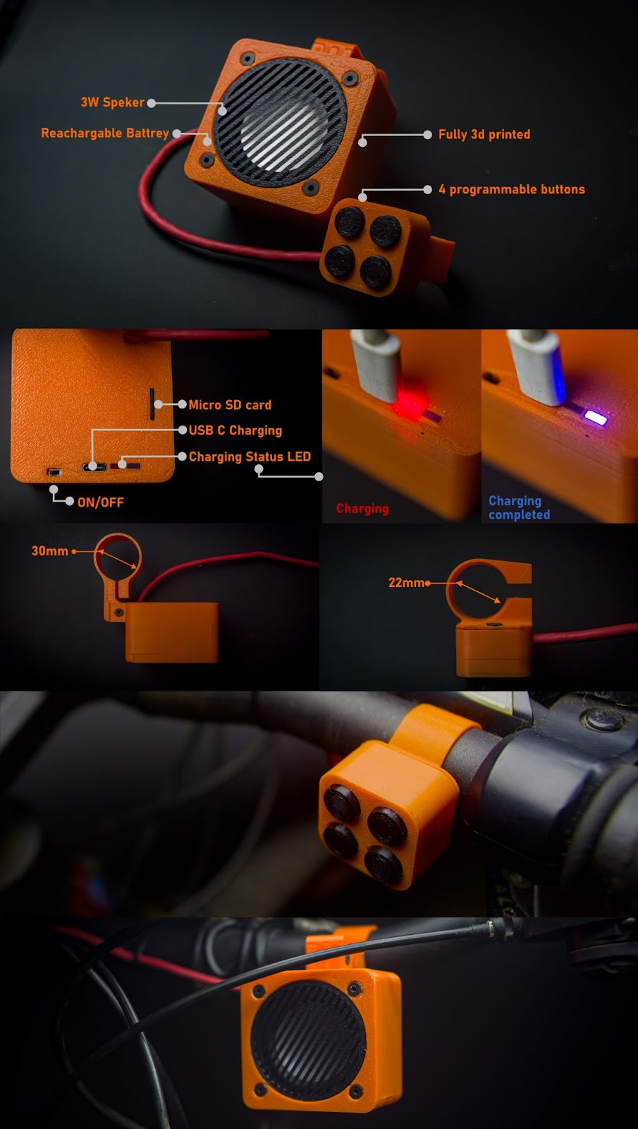
so in this project, we are going to make a digital bicycle horn with customizable sounds, we can produce up to 4 different sounds, and each track is saved on a micro-SD card in .mp3/wav format, we have 4 button inputs for playing sounds, each button is assigned to each track in the micro-SD card. also, it has a rechargeable battery, you can charge the battery with USB C, I also include a battery recharge indicator LED on the back side, and there is a small switch for ON/OFF. it is made from readily available components and completely 3d printable body parts.
Supplies

components
- 1*2 inch 4 ohm 3w speaker
- 1*Mini slide switch.
- 1*3.7v 1200mah battery (all batteries blow 30mm*48mm is supported in this design)
- 1*Red Rectangle flat LED 5*2mm (find the diffused LED on the drop-down menu)
- 1*Blue Rectangle flat LED 5*2mm(find the diffused LED on the drop-down menu)
- 1*TP 4056 battery charger USB C
- 1*DC-DC Step-Up Converter MT3608
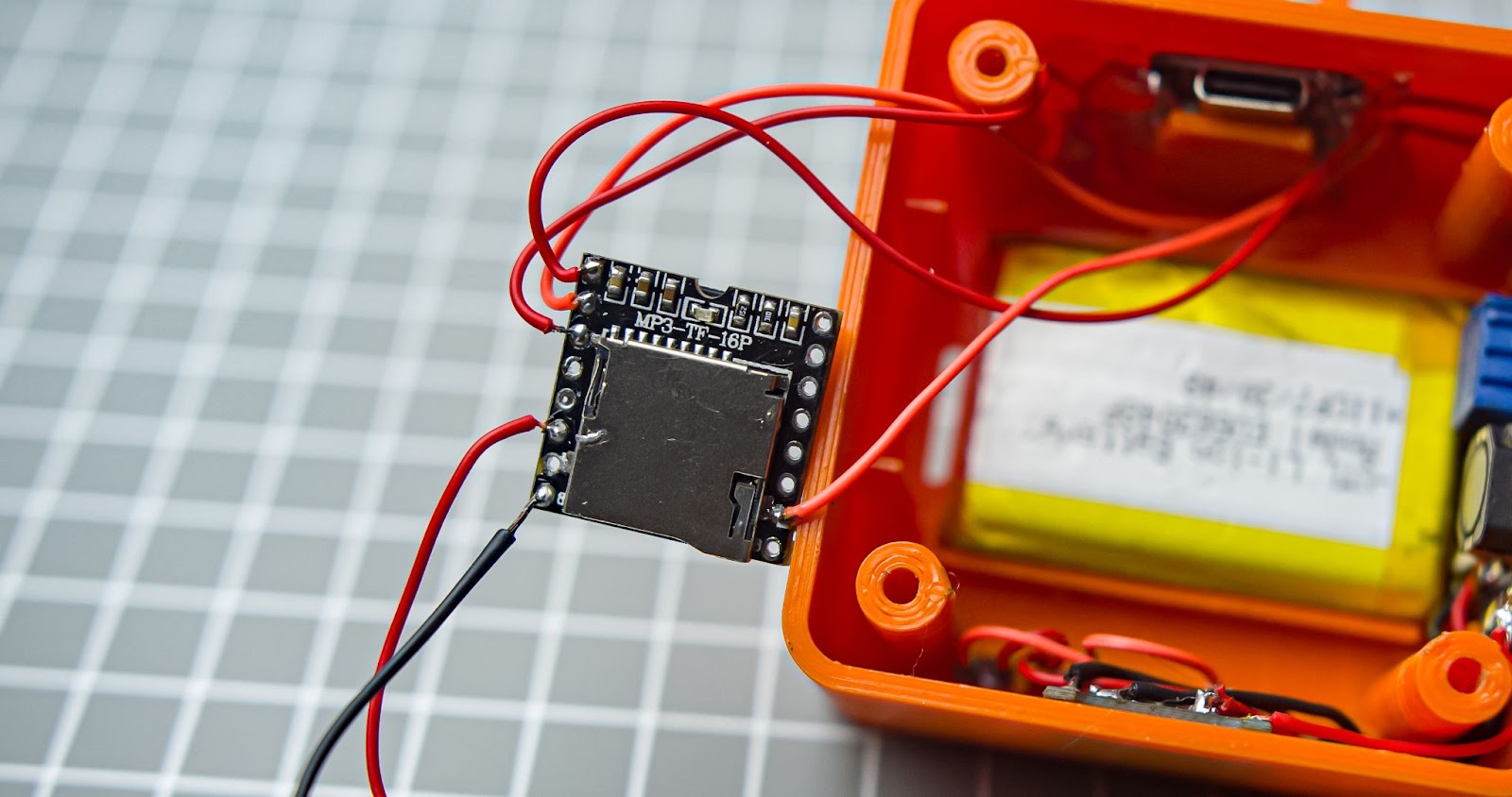
- 1*MP3-TF-16P(DFPlayer Mini)(always comes with header pin pre-soldered so remove header pins)
- 1*Seeed Studio XIAO SAMD21
- 1*Micro-SD card(Here I am using an 8GB Micro-SD it is overkill, you can go with the lower capacity)
- 4*6mm x 6mm x 9mm Micro switch push button ( select the height of 9mm)
- 3*M3 20mm CSK screw ( select length from the dropdown)
- 4*M3 12mm CSK screw( select length from the dropdown)
- 2*M3 16mmCSK screw( select length from the dropdown)
- 3*M3 Nuts(select length from the dropdown)
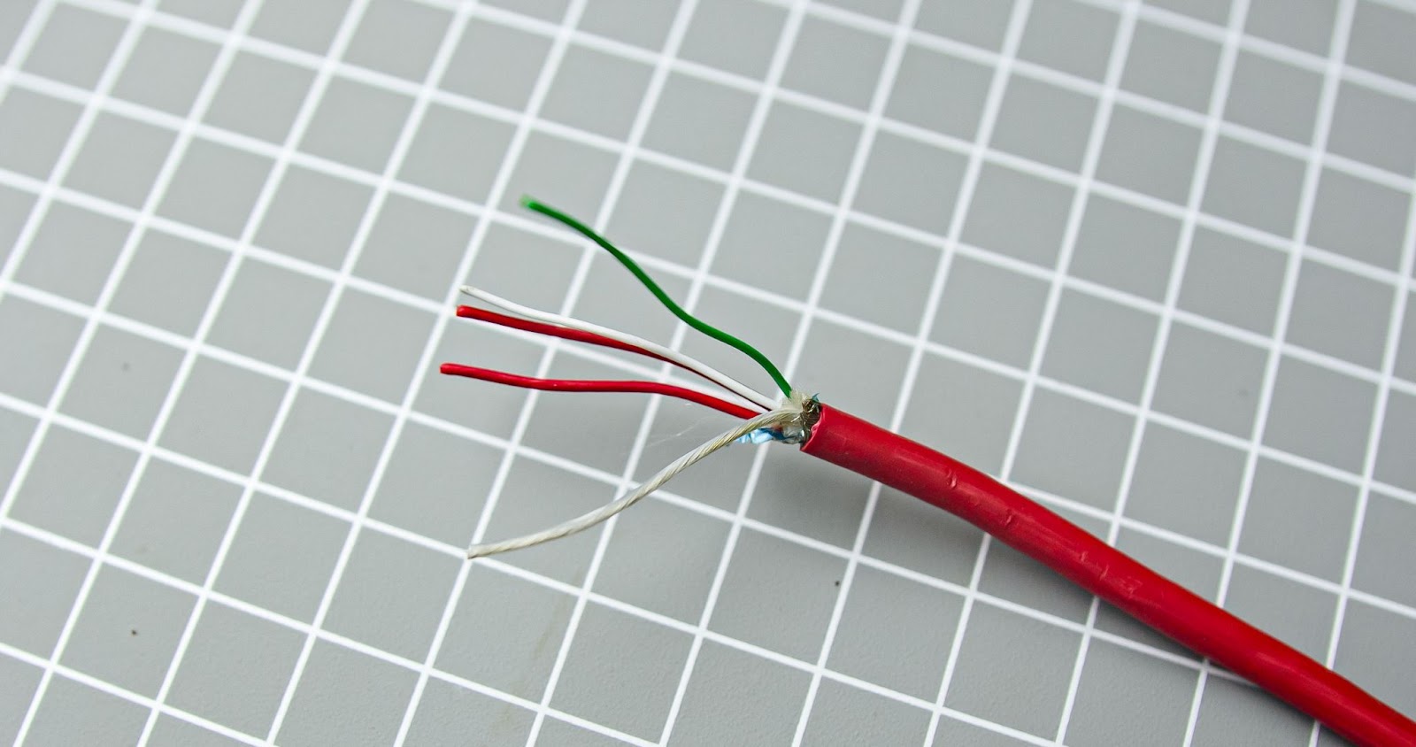
- 5-core wire 4mm OD x 500mm length (I am repurposing my old USB cable for this it is a fast-charging cable with 6 cores )
Tools
- Soldering iron
- Allen key set
- Nose plier
- Glue gun
- Wire cutter/wire stripper
- Heat shrink tube
- Multimeter
- Zip Ties (black)
- 3d printer ( 3d printing service )
Step 1: Modeling in Autodesk Fusion 360

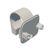
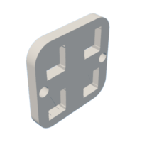
Used Fusion 360 to plan and design my project. The main body is designed to hold the battery and electronics without needing screws—it just snaps into place. To make sure everything stays secure, I used some hot glue. The button pad is also completely 3d printed including the button caps. I found some accurate models of the modules online. that made the design process much easier, all design files are given below
Attachments


Step 2: 3d Printing

I 3D printed all of this in PLA+ from Numakers . I used black and orange filament. which is a great combination. 0.2mm layer height and 100% infill, if you don't have a 3d printer you can find online 3d printing services
Step 3: Voltage Setting on MT3608
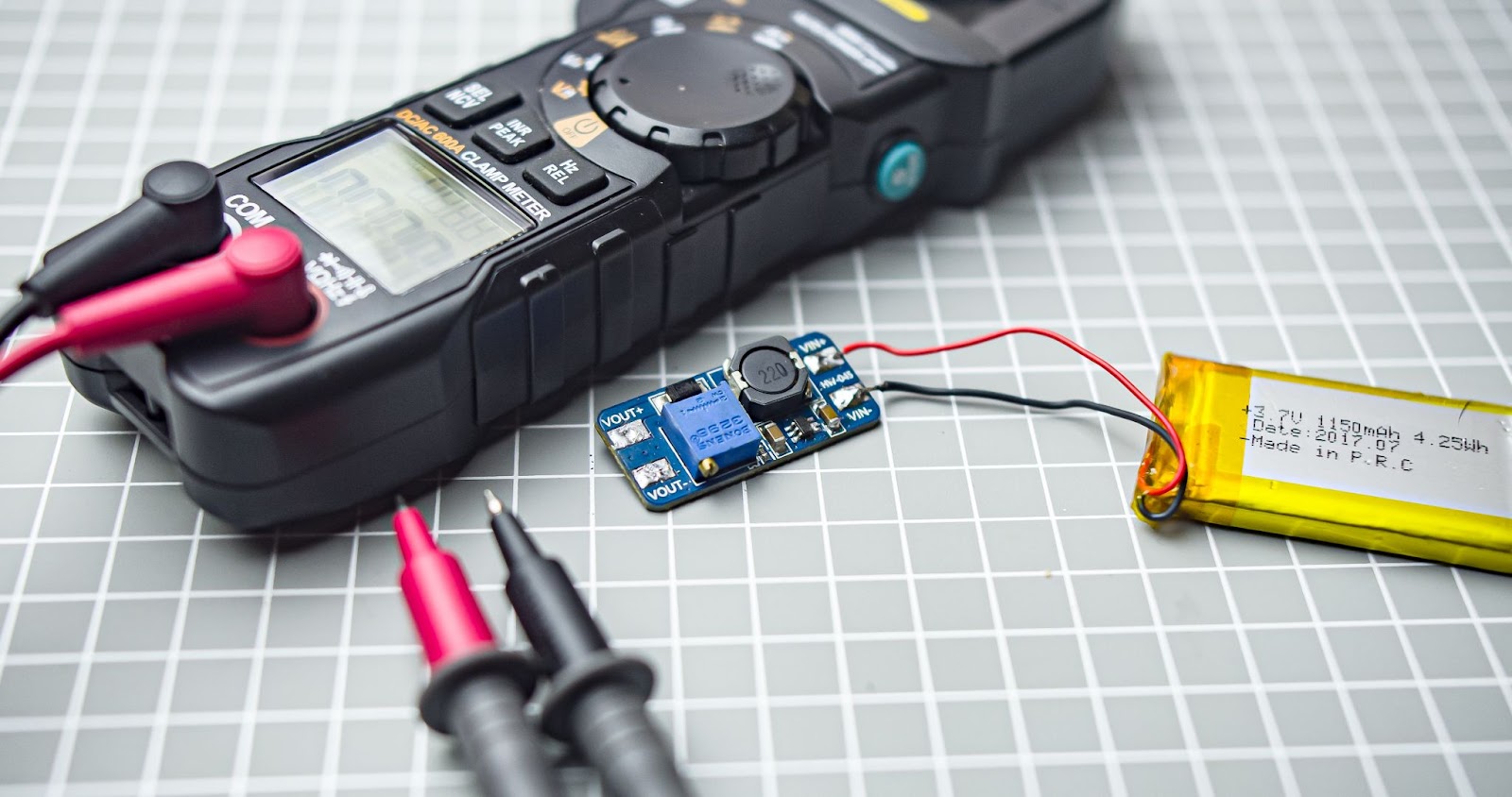
Before assembling we need to preset the voltage on MT3608, if you buy a new module you need to turn the potentiometer around 20 times or more in a counterclockwise position and then once you get the regulated voltage at the output you can use the module. Connect your battery to VIN+ and VIN- and set the voltage to 5v. measure it from the OUT+ and OUT- using a multimeter after that remove the battery input
Step 4: Removing Header Pins From MP3-TF-16P
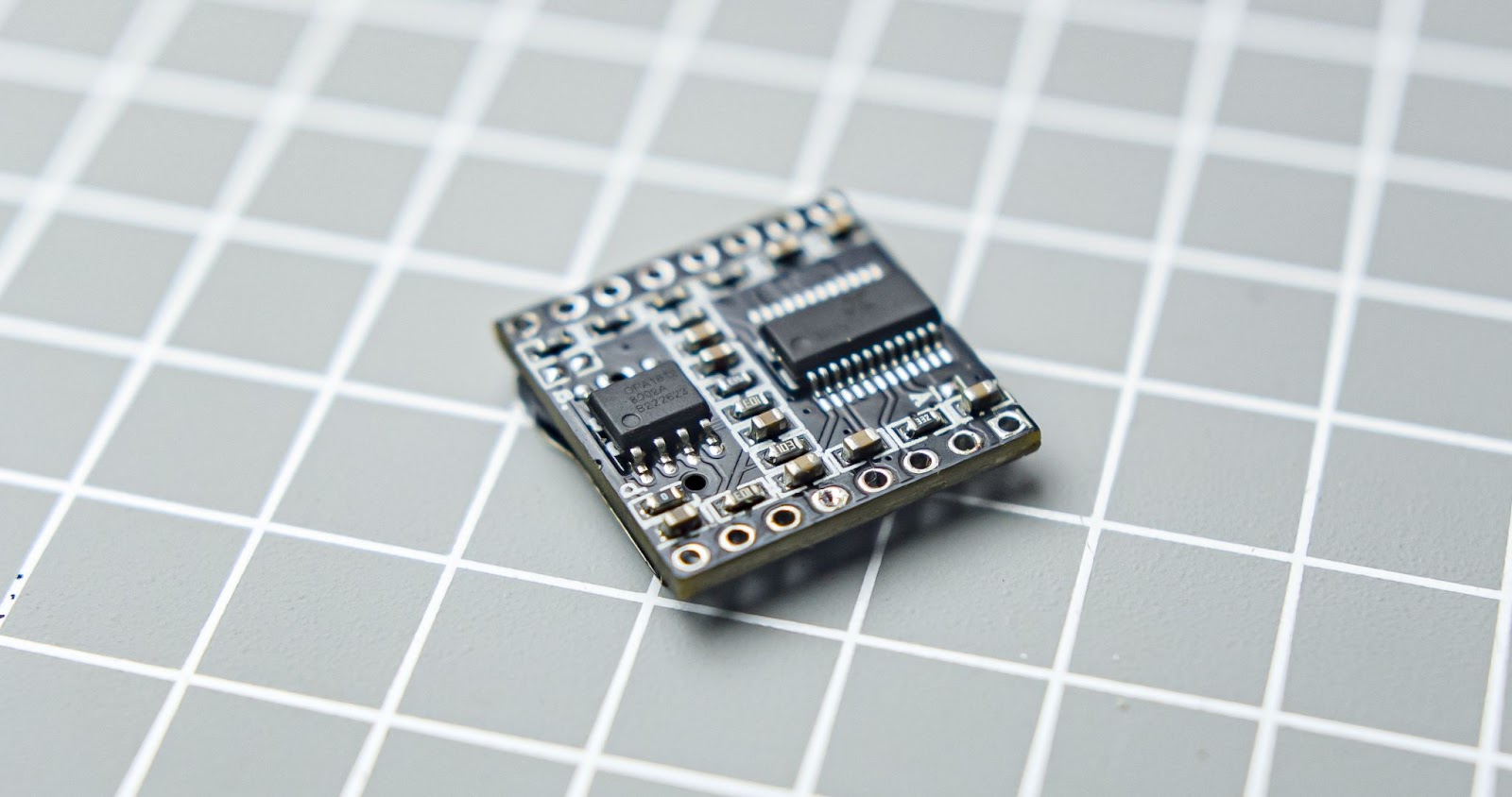 MP3-TF-16P always comes with a header pin pre-soldered but we need to remove it for this project, it is not easy if you don't have the right tools, I used a combination of desoldering pump and plier for removing the header pins. Try not to damage related components from the PCB. This tutorial helps me a lot
Step 5: Uploading Code to XIAO
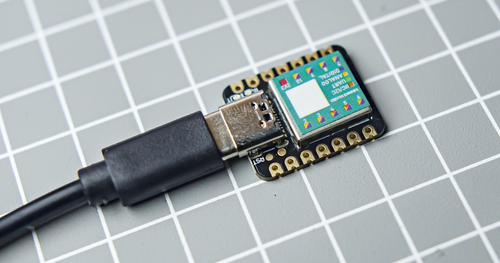
I always like to upload the code to the microcontroller before assembly. Here we are using a tiny Xiao SAMD21 from the Seeed studio, It carries the powerful ATSAMD21G18A-MU which is a low-power microcontroller.
Use full tutorials
After adding Xiao board to IDE we need to install the library for MP3-TF16P, a useful tutorial for installing the library link
Here is the code for our project. upload it to Xiao
#include "Arduino.h"
#include "SoftwareSerial.h"
#include "DFRobotDFPlayerMini.h"


#define RX D6 // RX pin of DFPlayer Mini connected to  digital pin 6
#define TX D7 // TX pin of DFPlayer Mini connected to  digital pin 7


#define BUTTON_1 D0 // Digital pin for button 1
#define BUTTON_2 D1 // Digital pin for button 2
#define BUTTON_3 D2 // Digital pin for button 3
#define BUTTON_4 D3// Digital pin for button 4


SoftwareSerial mySoftwareSerial(RX, TX); // Create a SoftwareSerial object
DFRobotDFPlayerMini myDFPlayer; // Create a DFPlayerMini object


void setup() {
  mySoftwareSerial.begin(9600); // Start the software serial communication
  Serial.begin(9600); // Start the serial monitor for debugging


  if (!myDFPlayer.begin(mySoftwareSerial)) { // Initialize DFPlayer Mini
    Serial.println("Unable to begin:");
    Serial.println("1.Please recheck the connection!");
    Serial.println("2.Please insert the SD card!");
    while(true);
  }


  // Set volume (0 to 30)
  myDFPlayer.volume(30);


  pinMode(BUTTON_1, INPUT_PULLUP); // Set button pins as inputs with internal pull-up resistors
  pinMode(BUTTON_2, INPUT_PULLUP);
  pinMode(BUTTON_3, INPUT_PULLUP);
  pinMode(BUTTON_4, INPUT_PULLUP);
}


void loop() {
  if (digitalRead(BUTTON_1) == LOW) {
    playSong(1); // Function to play song 1
    delay(500); // Add a small delay to prevent multiple triggers with one press
  } else if (digitalRead(BUTTON_2) == LOW) {
    playSong(2); // Function to play song 2
    delay(500);
  } else if (digitalRead(BUTTON_3) == LOW) {
    playSong(3); // Function to play song 3
    delay(500);
  } else if (digitalRead(BUTTON_4) == LOW) {
    playSong(4); // Function to play song 4
    delay(500);
  }
}


void playSong(uint8_t track) {
  myDFPlayer.play(track); // Play the specified track number
  Serial.print("Playing track ");
  Serial.println(track);
}
Step 6: Wiring Diagram
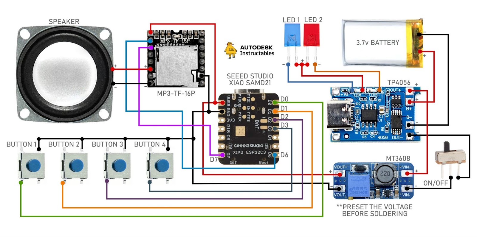
Now we can start the assembly.All components are placed in the side wall for utilizing the space and easy wiring
Let's begin
Step 7: Speaker Unit Assembly
Step 1
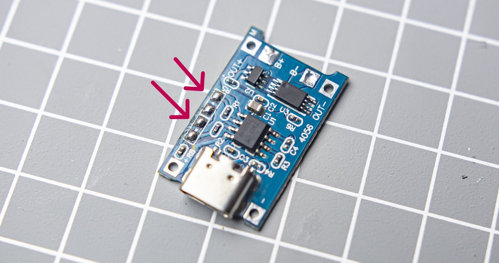
Remover the 2 charging status led
Step 2
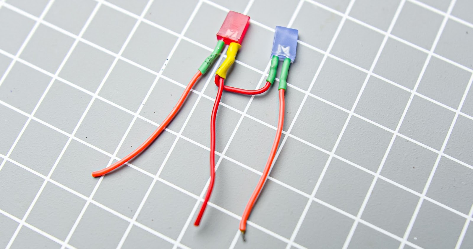
Connect wires for 2 led +ve terminals is common , and one -ve for red and -ve on blue
Step 3
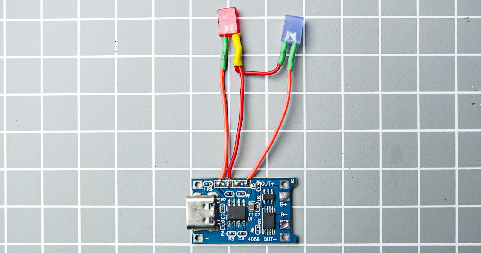
Connect the led wires to the BMS
Step 4
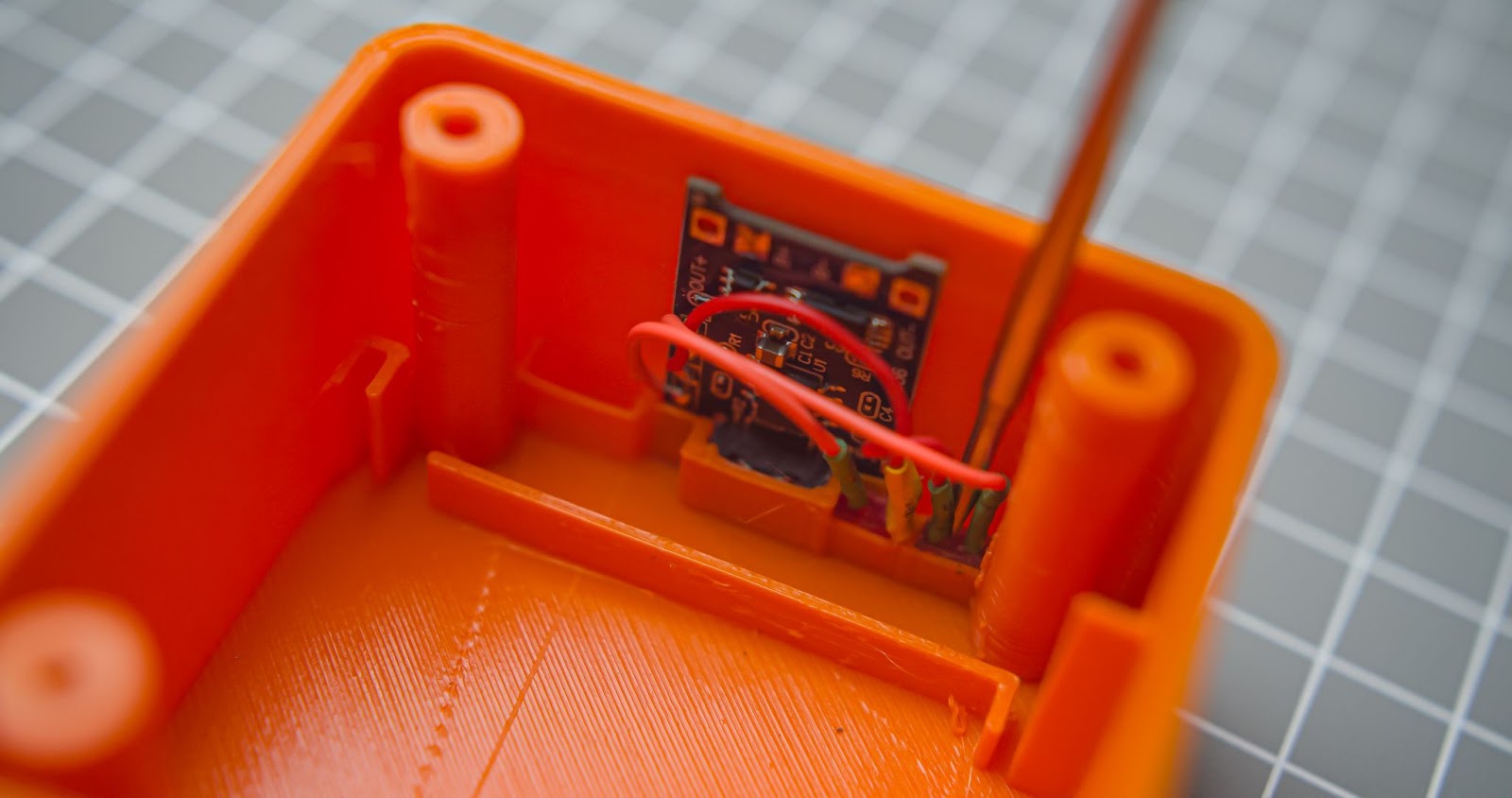
Push down the BMS and LED through the 3d print using a nose plier. Don't damage the led
Step 5
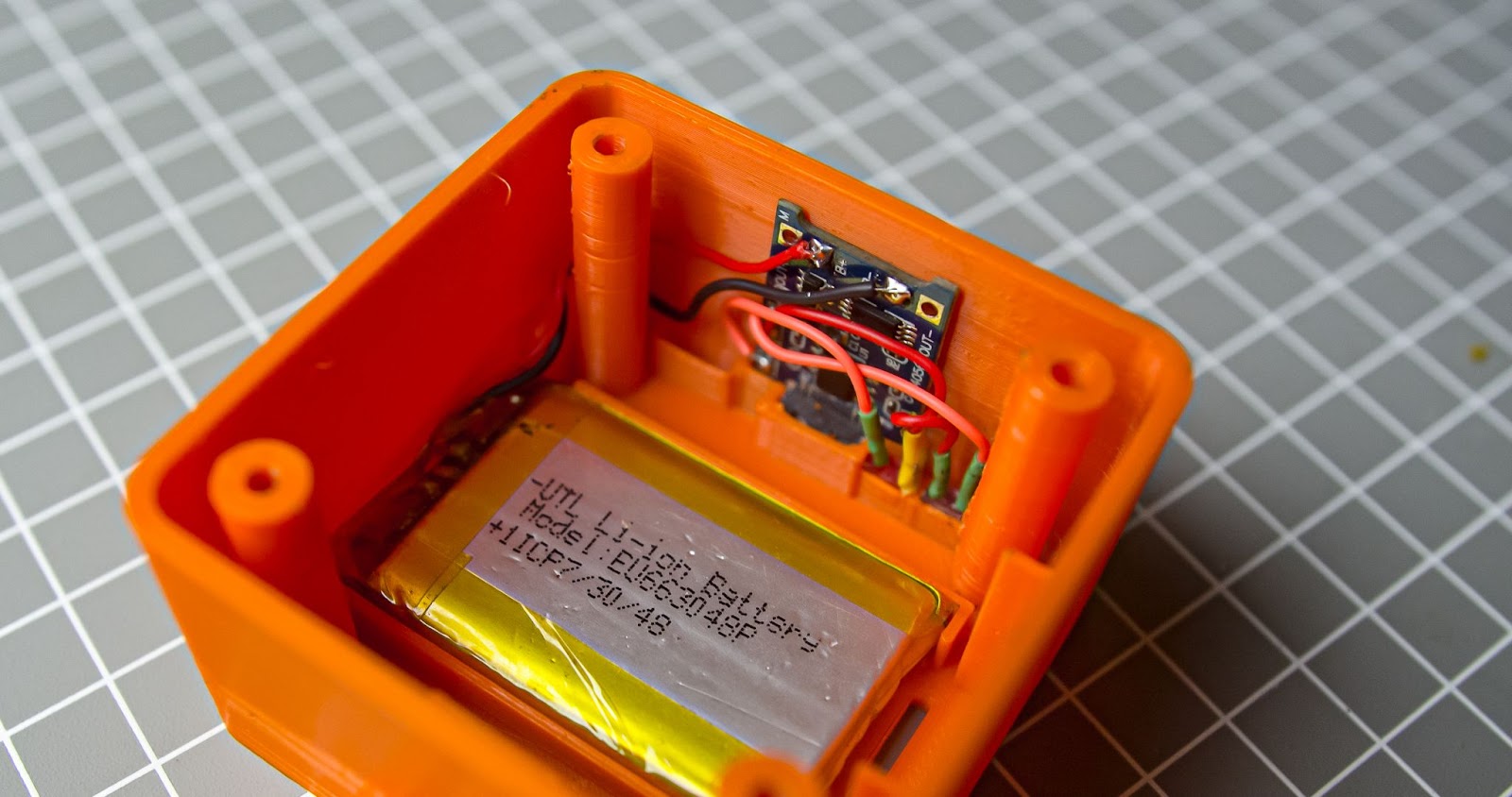
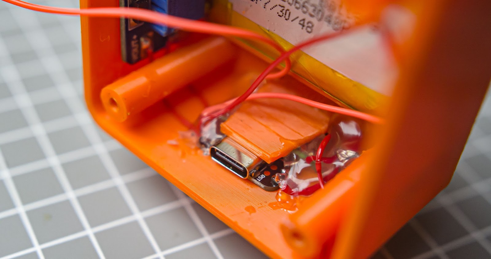
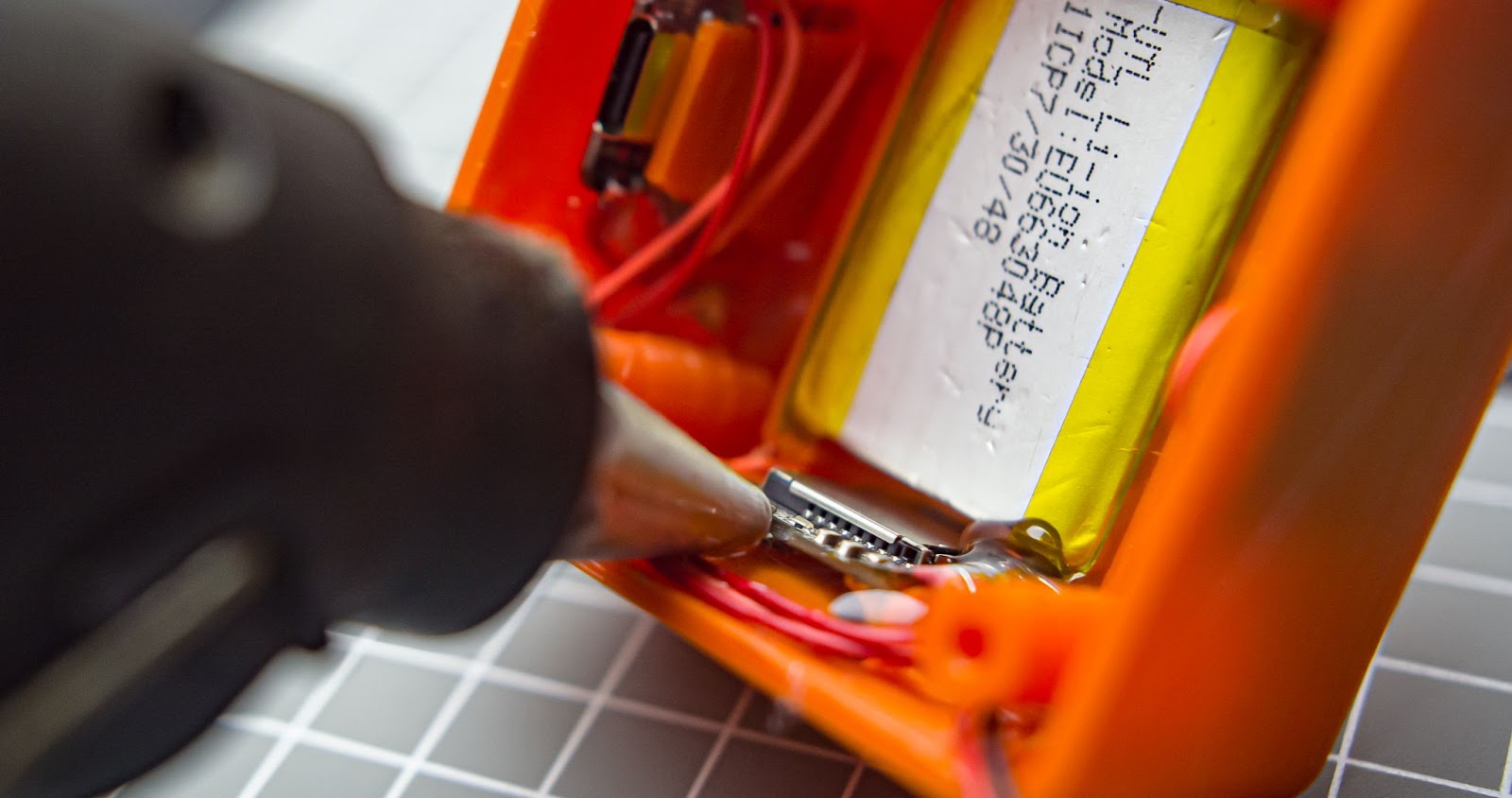
We need to wire up the battery to the BMS, connect the +ve terminal of the battery to the B+ of BMS and -Ve to the B-, soldering place the battery on a 3d printed slot
Step 6
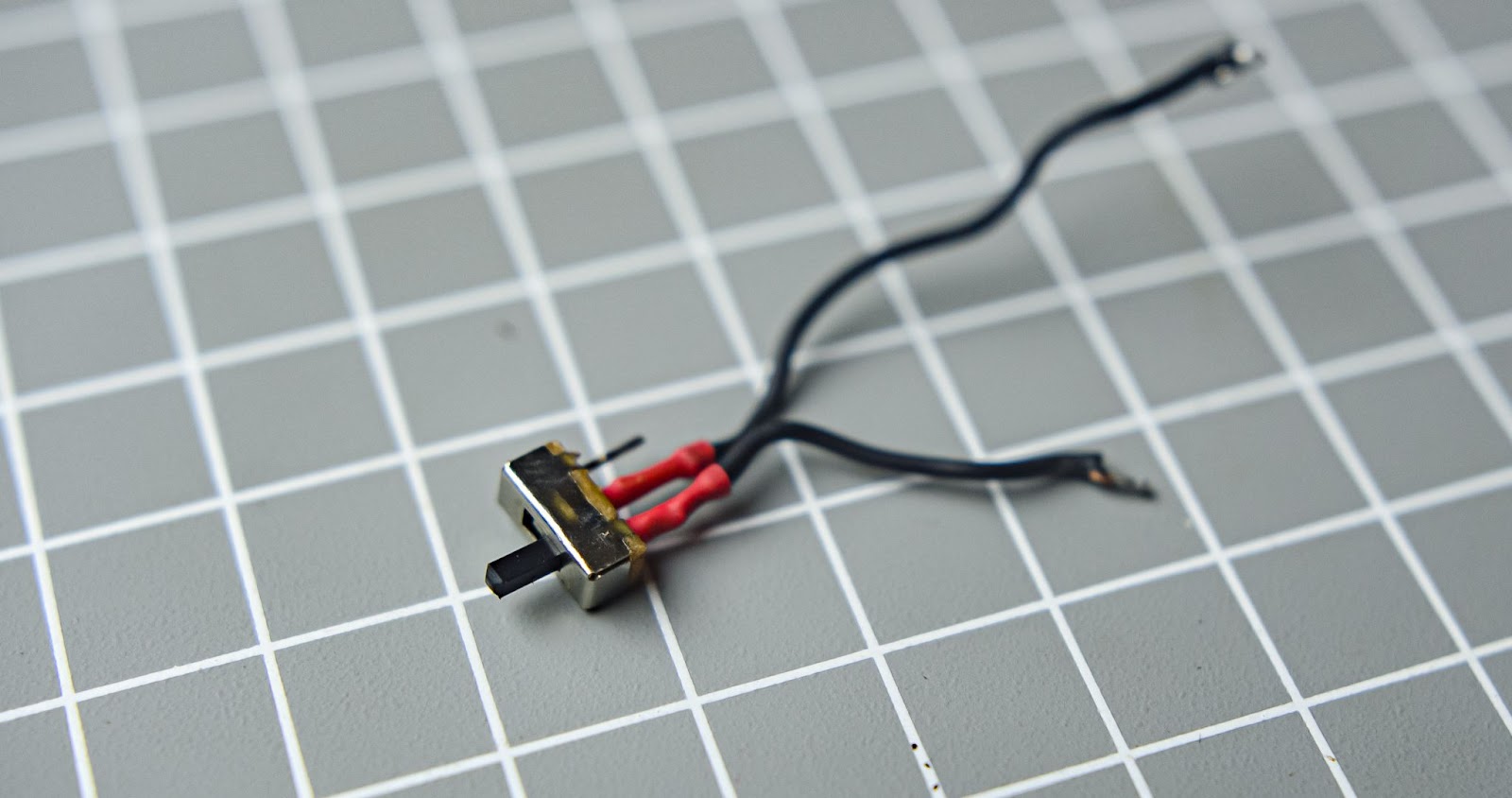
Solder two wires to the power switch, push in the power switch to the 3d printed slot
Step 7
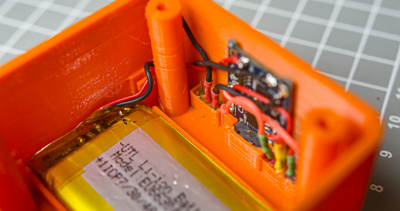
Connect the BMS OUT+ to the VIN+ of MT3608 and VIN- to the second terminal of the power switch , you can insert MT3608 into the 3d printed slot

Step 8
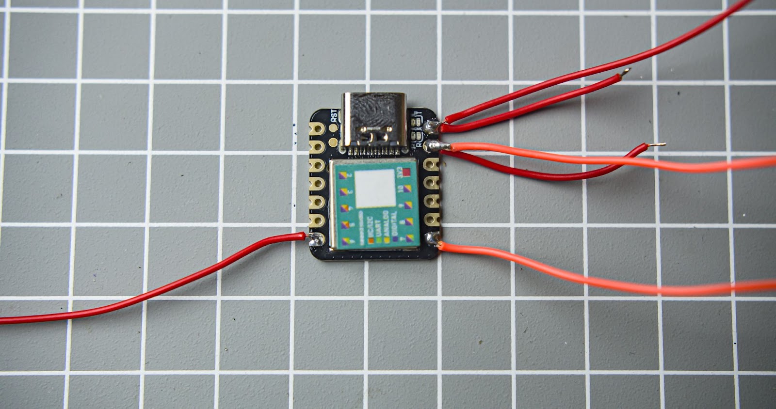
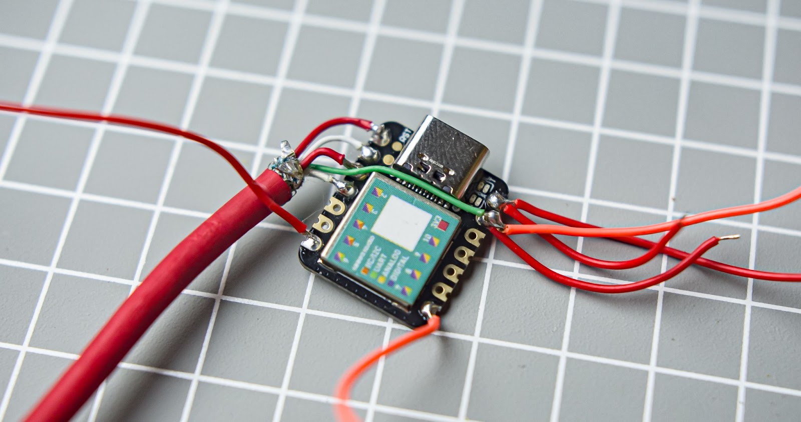
Pre-soldered the wires for the xiao with an appropriate length of the wire
Step 9
Strip down 20mm of wire from the 5-core wire
Step 10
Run the wire through the hole in the main body

Step 11
Connect the 5 core wire to GND, D0,D1,D2,D3 pins of the xiao
Step 12
Push down the wire and xiao into the 3d printed slot and glue the 5-core wire and xiao with a hot glue gun
Step 13
Connect the VUSB and GND of Xiao to the +VOUT and -VOUT of MT3068 respectively. After that, we can connect Xiao and MP3-TF-16P. Xiao D6 and D7 to RX and TX pin of MP3-TF-16P, xiao VUSB, and GND to the VCC and GND of MP3-TF-16P. Also, solder two wires from MP3-TF-16P for the speakers.
Step 14
After completing the wiring we can glue the MP3-TF-16P to the 3D-printed slot
Step 15
Connect the speaker
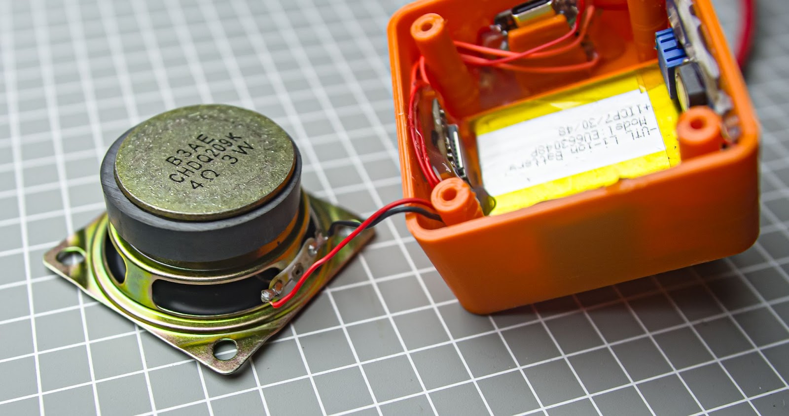
Step 16
Place the speaker inside the main body and align the screw holes
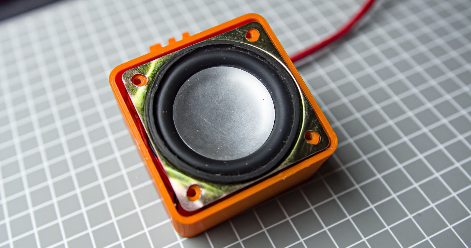
Step 17
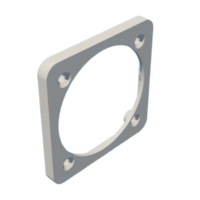
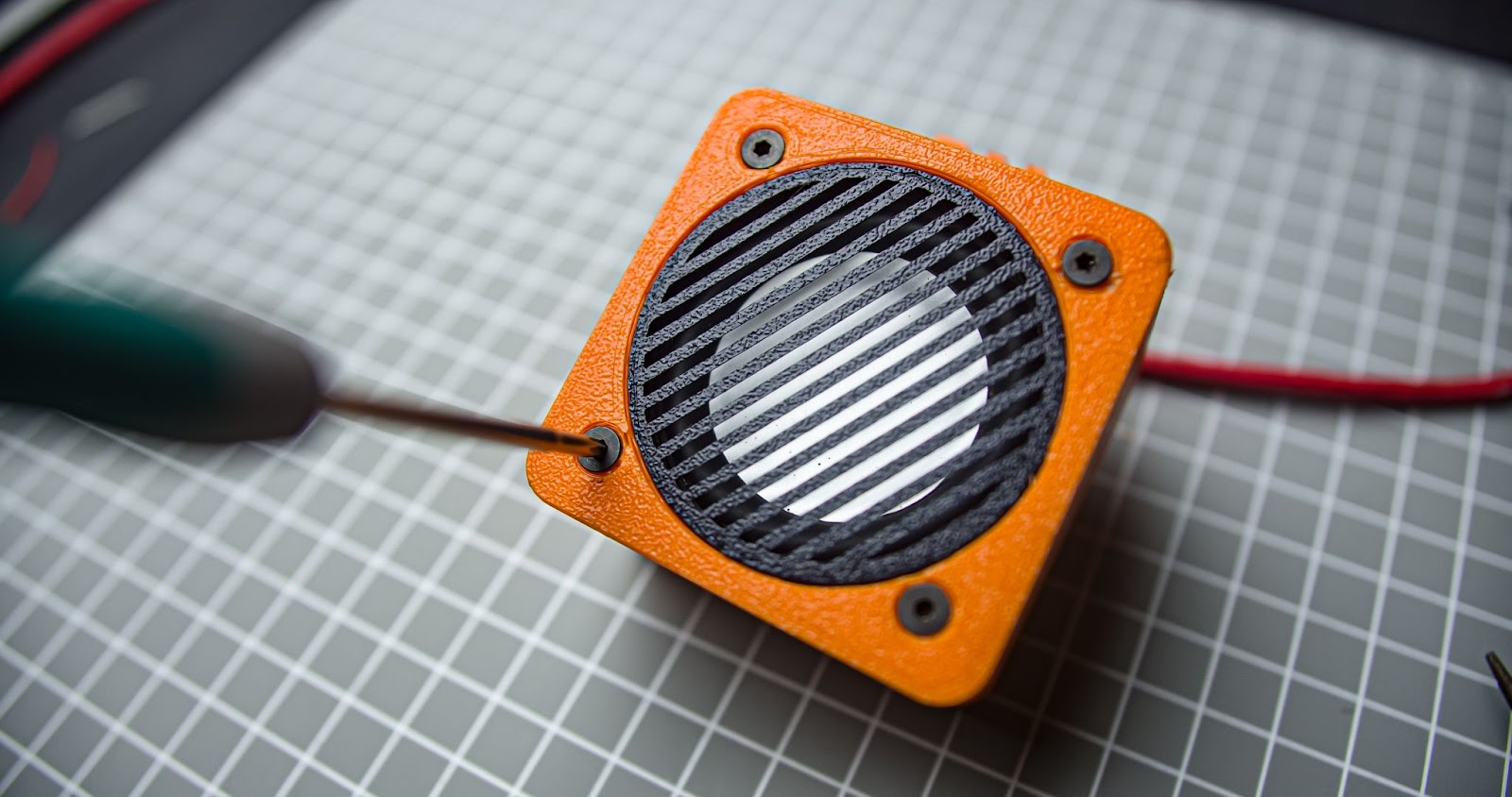
Insert the speaker grill into the front cover
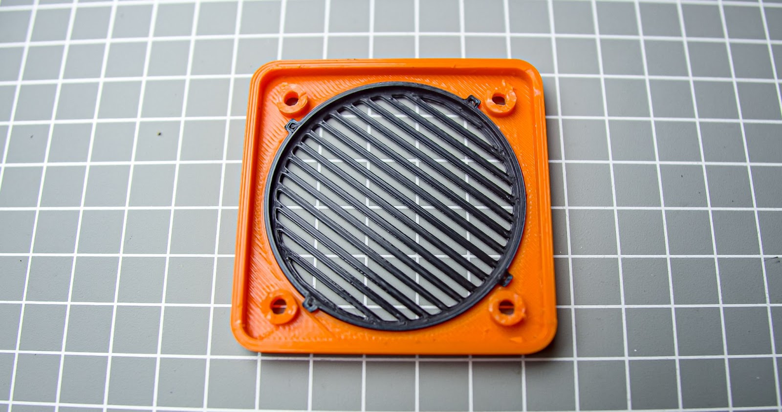
Step 18
Screw in the front cover to the main body with M3*12mm
Step 19
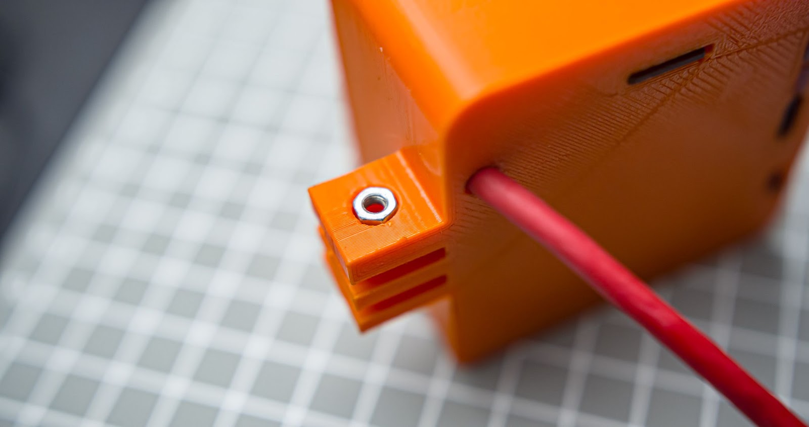
Insert a m3 nut into the slot in the mounting point
Step 20
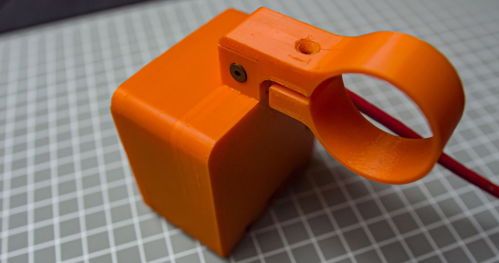
Put the bicycle mount to the main speaker body and tighten it with M3*20mm screws
Step 21
Insert the m3 nut into the mount
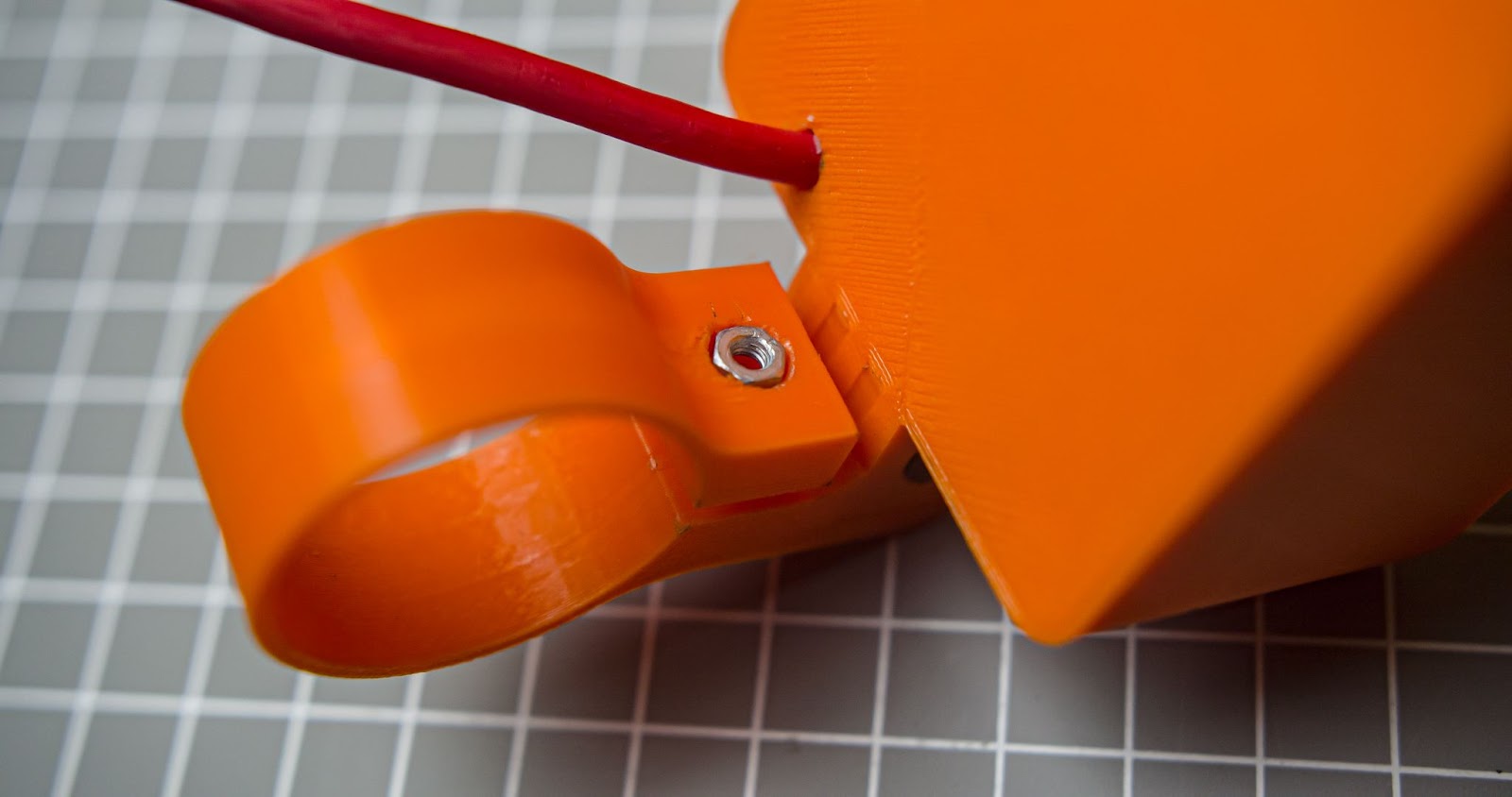
We just completed assembly of main speaker unit
Step 8: Button Pad Assembly
Step 1
Insert the four push buttons to the slot in the 3d printed button support
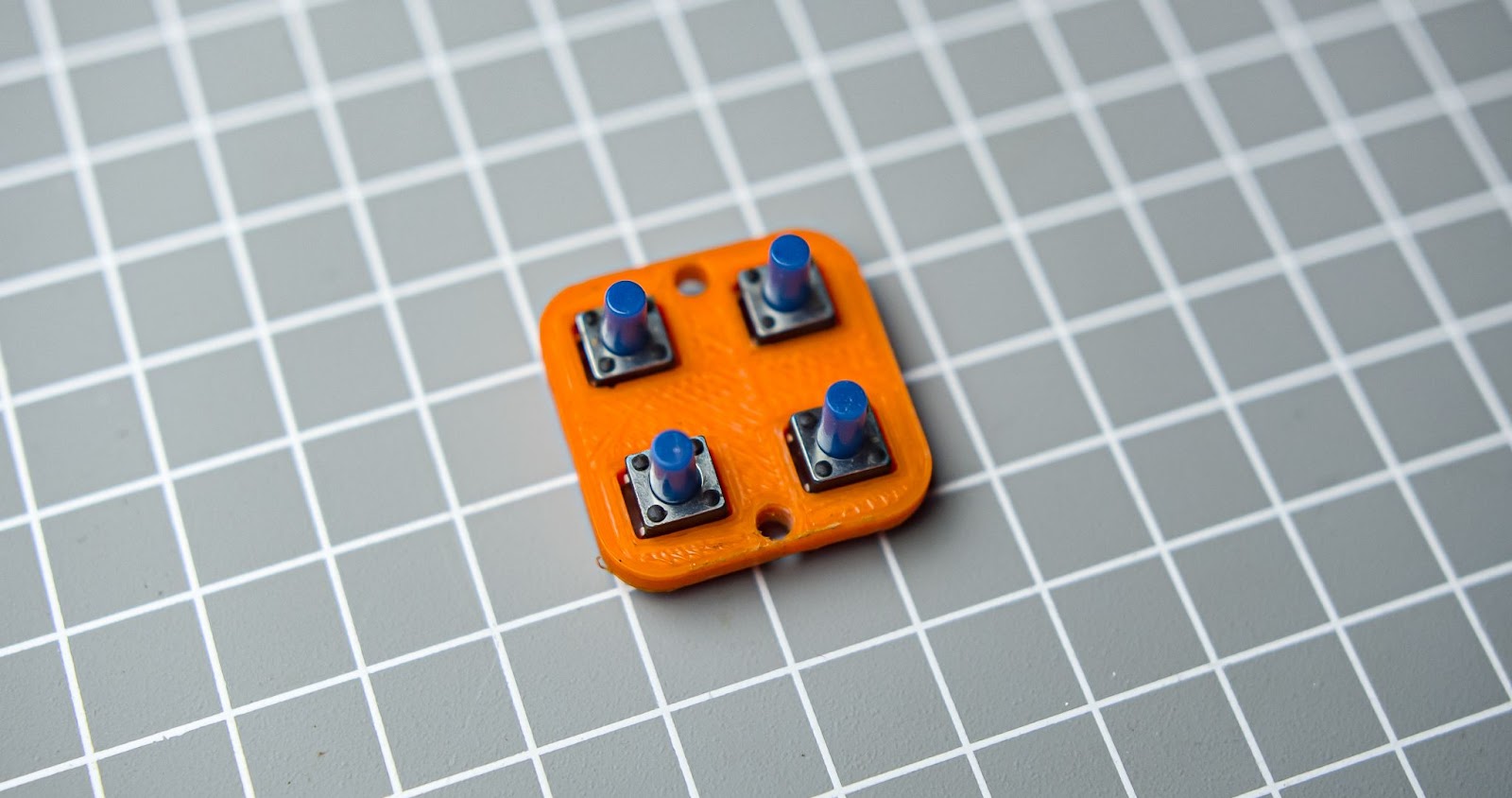
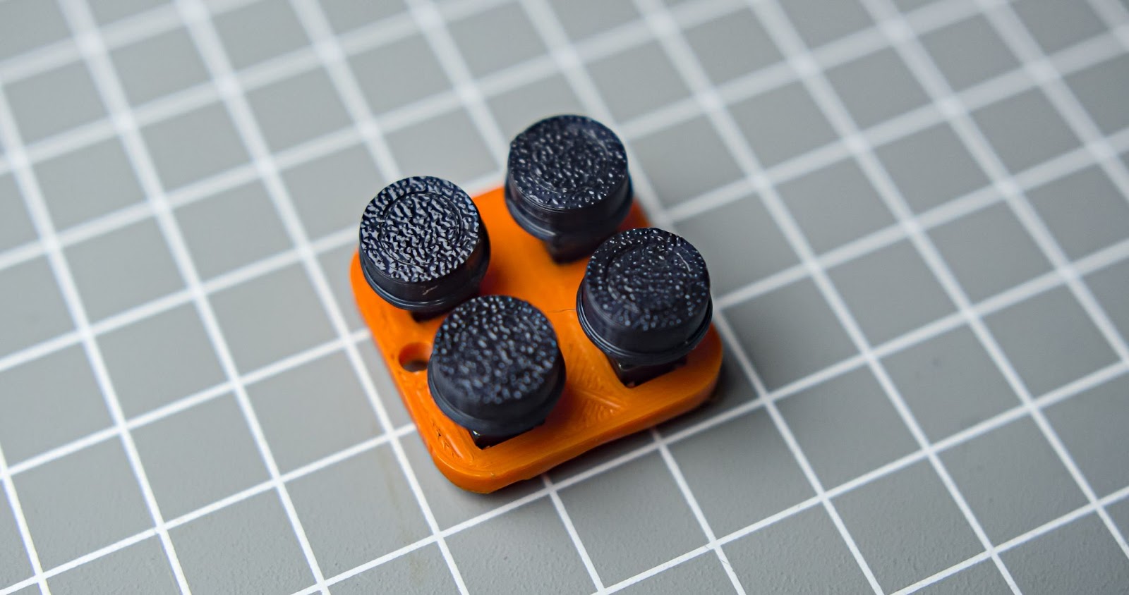
Step 2
Push down all four button caps
Step 3
Follow this wiring diagram
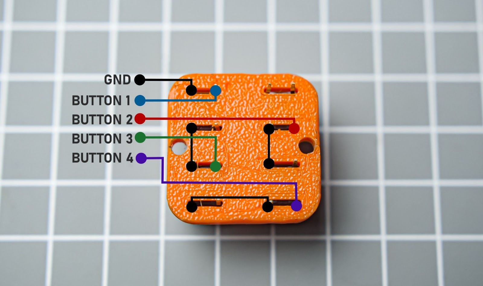
Connect all ground of buttons
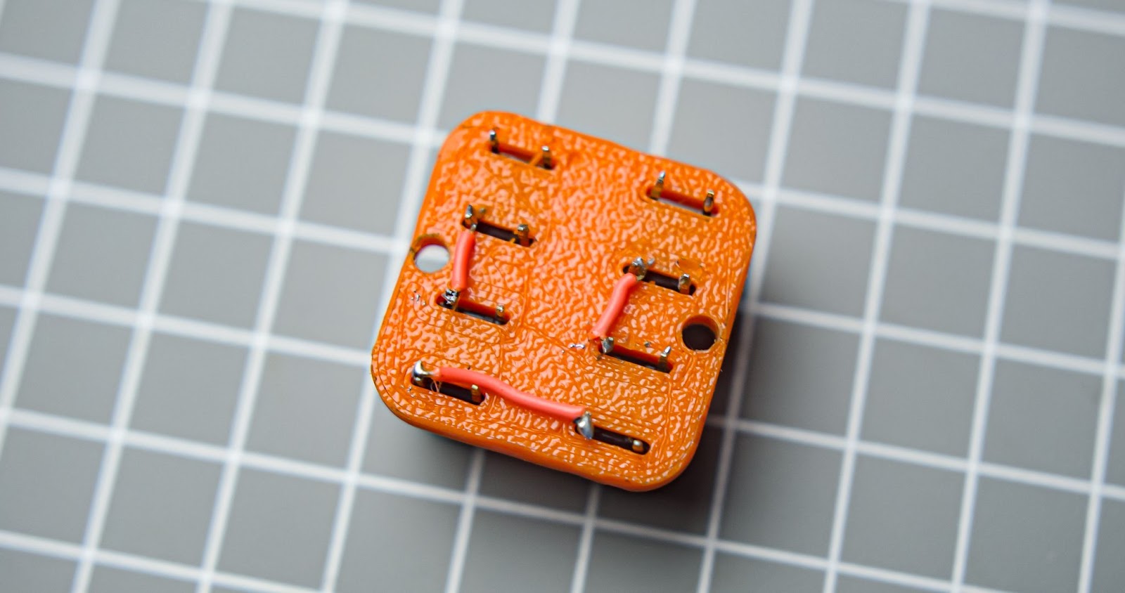
Step 4
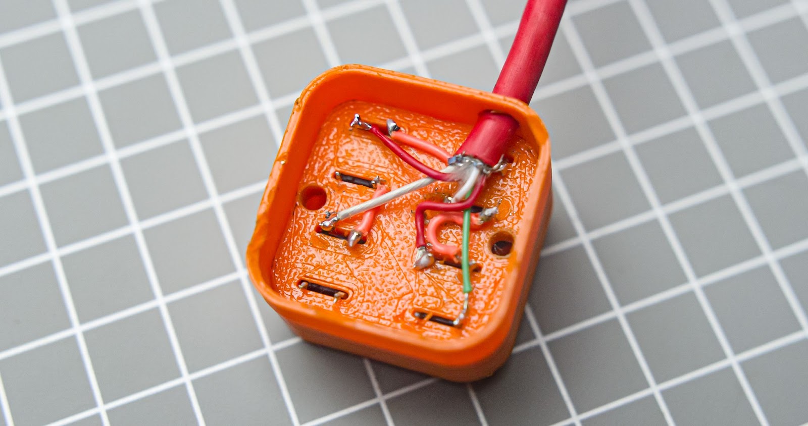
Push down the button assembly to the main body,run the cable through the hole in the main body, and cut the 5 core wire at the length of 25cm from the main speaker unit .solder all wires to the respective buttons,
Step 5
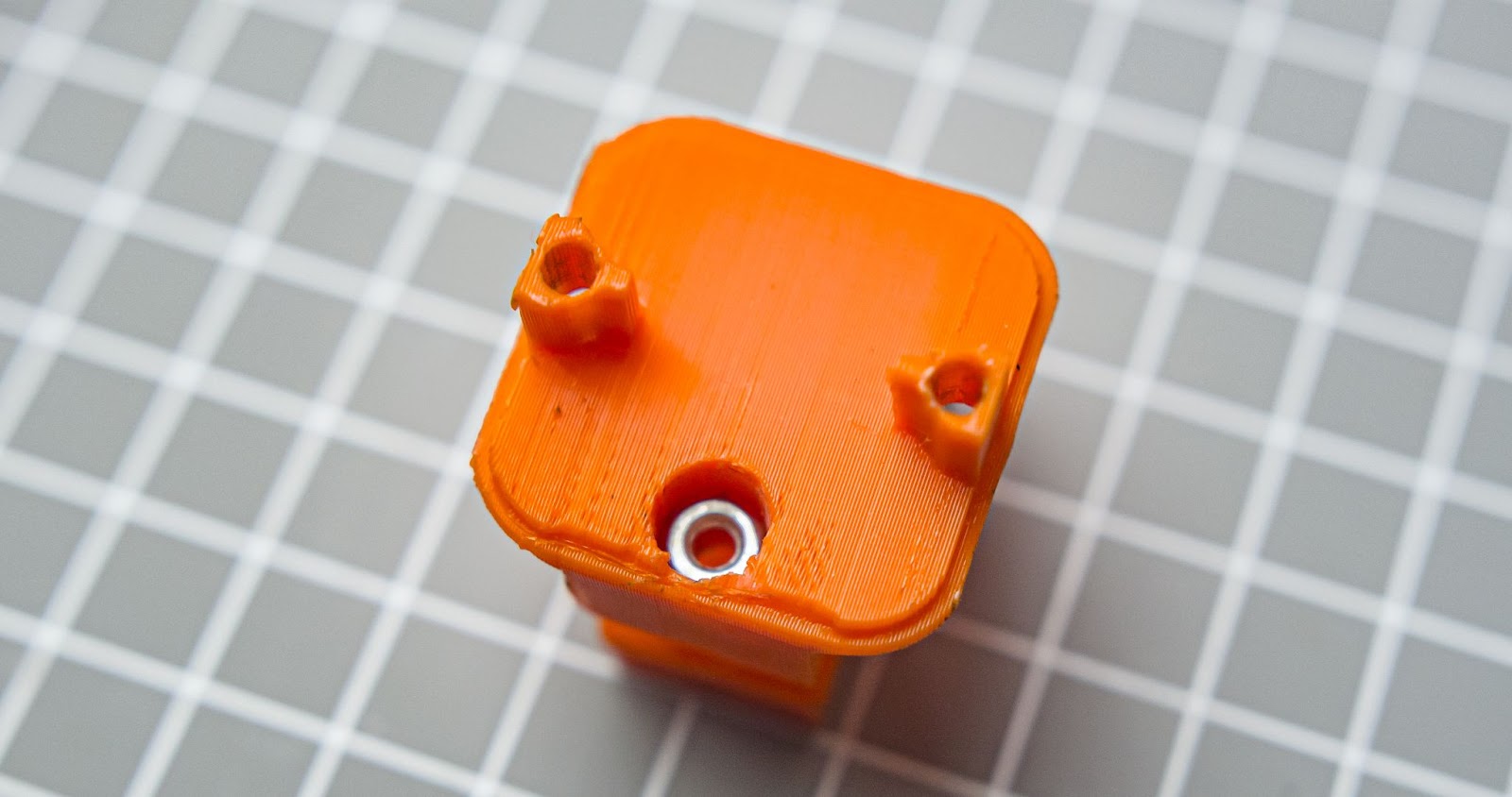
Insert an m3 nut into the hole in the button mount
Step 6
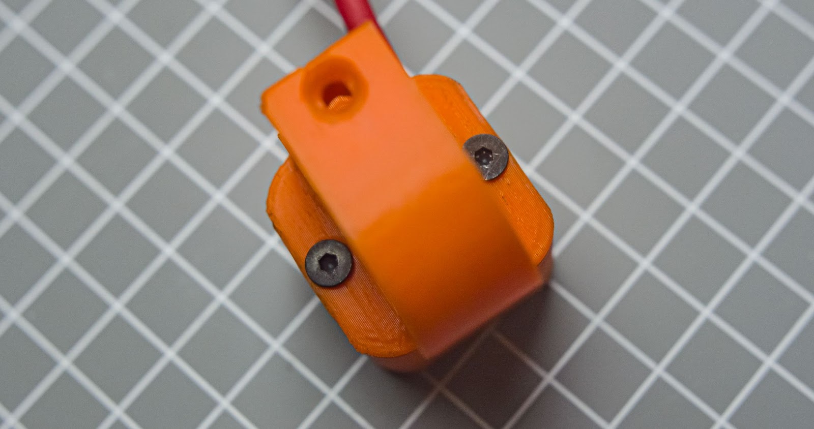
Close down button assembly with two M3*16mm screws
Step 9: How to Program the Sounds
Step 1
Connect SD card to a computer with card reader and format your sd card
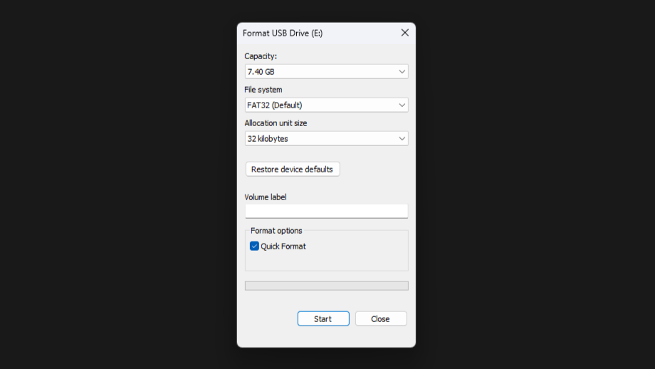
Step 2
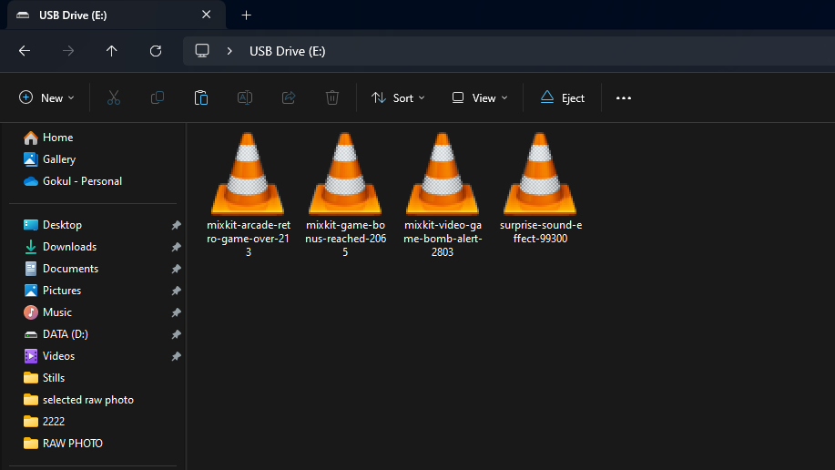
You can copy any MP3 or WAV audio to the Micro SD card ( NO TIME LIMITATION), i just copied about 4 audio files that I downloaded from the internet.
if you need to find a new sound you like,
- Just search the sound effects in the YouTube
- Copy the video URL
- Find a YouTube to MP3 online converter
- Past the URL
- Convert it to MP3 and download it
- Copy it to a Micro SD card
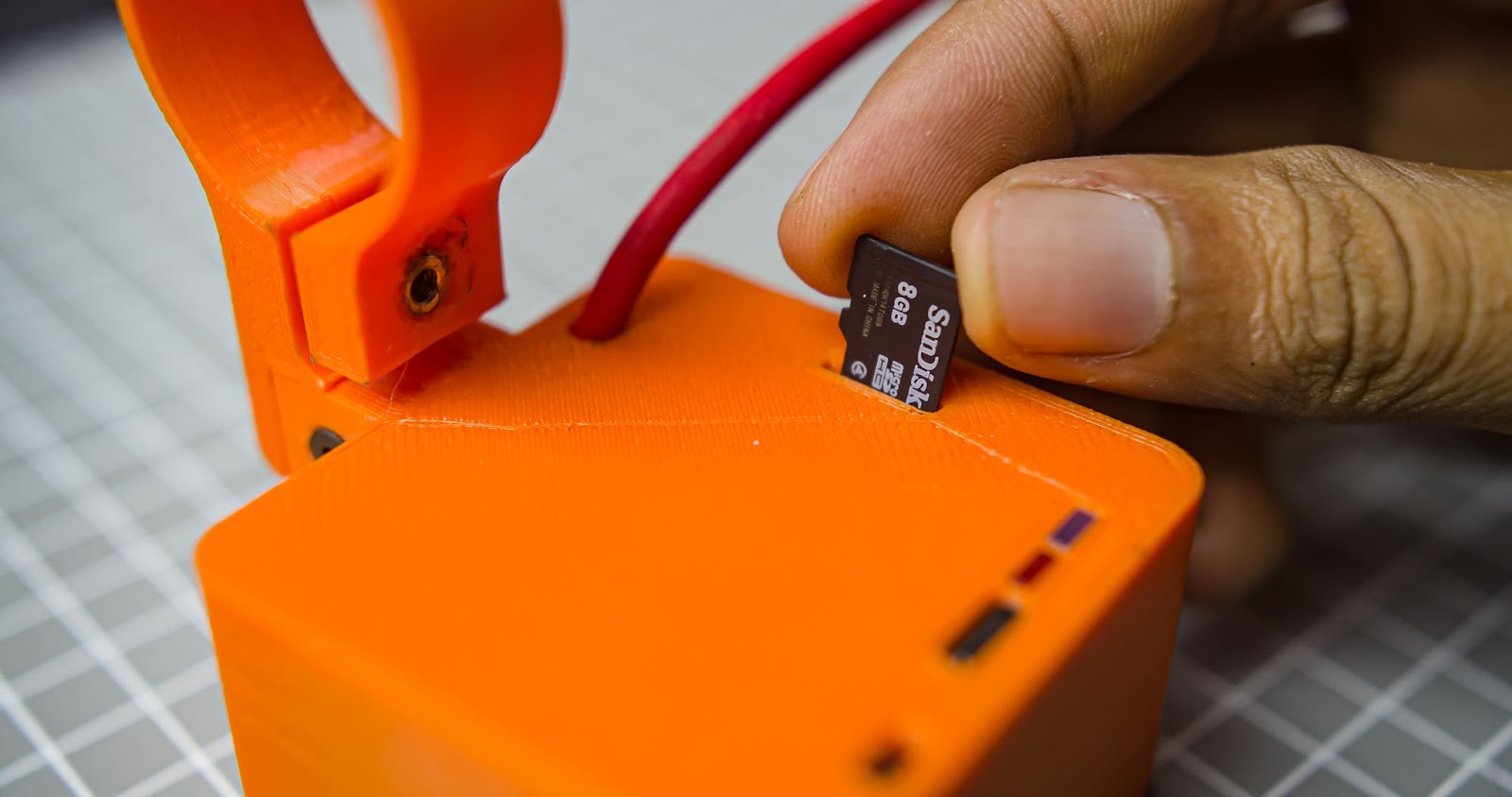
Step 3
Insert the micro SD card into the SD card slot, each track will be assigned to 4 buttons
Step 10: How to Mount It to the Bicycle
Watch the video that I made. It looks cinematic right ?😂 ,I used two M3*20mm Scews
Step 11: Final Thoughts
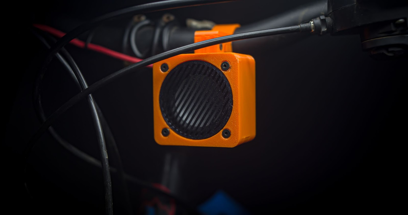 Well, we made it, it looks cool and unique, you can use it for more purposes than a horn, and you can record your voice to play in this. if you need to sell ice cream or some things in your bicycle/vehicle, you can play advertisement sounds in it. the possibilities are endless.
Let me go for a ride with it, hope nobody will steal it this time 🕵🏽 😂

Judges Prize in the
Make Some Noise Contest


