

Introduction: Digital Clock From 1800s (not Really)


Hi guys, how are you doing today?
Well, today's interesting item is a metal alarm clock from the 1800s that uses modern hardware and obtains time from the internet.
The goal was to create a desk clock that resembles the traditional metal alarm clocks that have been around for more than 200 years.
It has the same design as a traditional metal alarm clock and even has bells with a handle and a stand.
The custom ESP12F-powered circuit at the center of this project shows the time obtained by the ESP12F when it connects to the internet using an NTP client. It also contains an SSD1306 OLED display and a few other necessary components.
It has a 3.7V Li-ion battery inside, which is coupled with a power management module to increase 3.7V to 5V so that the Clock circuit may be powered.
This Instructables is about the built process of this clock, so let's get started!
Supplies
Following were the materials used in this built-
- ESP8266 12F module
- Custom PCB
- 10K Resistors
- AMS1117 Voltage Regulator 3.3V
- 1uF Capacitor 1206
- 10uF Capacitor 1206
- Header Pin CON4
- SSD1306 OLED Display
- 3D Parts
- Nuts and bolts M3
- M4 Threaded inserts\
- M4 Bolts
Step 1: Metal Clock


Although the history of metal alarm clocks is not entirely clear, they have been used for ages. German inventor Peter Henlein is thought to have created the first mechanical alarm clock around the beginning of the 15th century. Although they were large and required manual winding, these early alarm clocks offered a dependable means of waking up in the morning.
Then there was the well-known Levi Hutchins alarm clock, which rang only at four in the morning and was manufactured in 1787.
Another alarm clock with a mechanical mechanism and customizable time was created in 1847 by the French inventor Antoine Redier.
Alarm clocks shrunk and became more compact as technology advanced, and metal casings became a more typical material for clock casings. The original metal alarm clocks probably had a wind-up mechanism that powered both the clock and the alarm, and they were probably constructed of brass or iron.
Metal alarm clocks have changed over time to incorporate electrical power sources, digital displays, and a variety of features, including snooze buttons, radio alarms, and even voice-activated alarm settings.
Even in this project, the clock is digital, and made of electronics, and the construction is made simpler by using contemporary technologies like 3D printing.
Step 2: Design and 3D Parts

The design of this clock was inspired by a typical metal alarm clock with bells and a handle.
The PCB was first made, after which I arranged everything else around it before modelling the design in Fusion360.
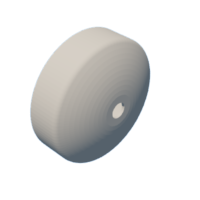
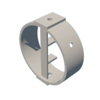
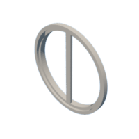
The central section, which contains the lithium cell and the boost circuit, is where the PCB is first attached to a PCB Holding Ring. A lid component with a mounting slot for the switch and a 5mm hole for the LED is then added to the underside of the board.
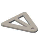
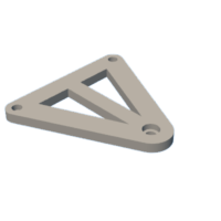
Also, two clock stands that elevate the timepiece from both sides have been designed. The center body of the clock will be connected to these holders or stands using M3 bolts.
The famous metal alarm clock with a bell design was replicated using two bells and a handle.
Each object was modeled, exported as STL files, and then 3D printed using an Ender 3 pointer with a 0.4mm nozzle, 0.2mm layer height, and 20% infill.
While my intention was to paint all parts except for the PCB Holding ring with metal silver paint, only the PCB Holding ring was printed with black PLA. All other items were printed in white PLA.


Step 3: Internet Clock PCB Assembly


The main Circuit is being reused from a previous project which you can check out from here-
Let's look at its quick construction steps.
- We first start the PCB Assembly Process by adding Solderpaste to each component Pad one by one with help of a Solder Paste Dispensing Needle
- Next, we gather all the SMD Components and place them in their location by using an ESD Tweezer.
- We then place the PCB on a Reflow Hotplate to melt the solder paste.
- Next, we place the header Pin and USB Port in their place and solder them using a standard soldering Iron.
- At last, we place the SSD1306 Display on the header pin connector, and the Board is now completed.
Step 4: Working and Code
Here's the code for this project. It uses an NTP server, which is, in short, a protocol for setting time through the internet.
#include "NTPClient.h"
#include "ESP8266WiFi.h"
#include "WiFiUdp.h"

#include <Wire.h>
#include <Adafruit_SSD1306.h>
#include <Adafruit_GFX.h>

#define OLED_WIDTH 128
#define OLED_HEIGHT 64

#define OLED_ADDR   0x3C

Adafruit_SSD1306 display(OLED_WIDTH, OLED_HEIGHT);

const char *ssid = "addyourSSID";
const char *password = "andYourPass";

const long utcOffsetInSeconds = 19800; //Change this according to your GTM

char daysOfTheWeek[7][12] = {"Sunday", "Monday", "Tuesday", "Wednesday", "Thursday", "Friday", "Saturday"};


WiFiUDP ntpUDP;
NTPClient timeClient(ntpUDP, "pool.ntp.org", utcOffsetInSeconds);

void setup(){

  display.begin(SSD1306_SWITCHCAPVCC, OLED_ADDR);
  display.clearDisplay();
  Serial.begin(115200);
  WiFi.begin(ssid, password);

while ( WiFi.status() != WL_CONNECTED ) {
delay ( 500 );
Serial.print ( "." );
}

timeClient.begin();
}

void loop() {
timeClient.update();

display.clearDisplay();
display.setTextSize(3);
display.setTextColor(WHITE);
display.setCursor(13, 0);

display.println(daysOfTheWeek[timeClient.getDay()]);

display.setTextSize(2);
display.setTextColor(WHITE);
display.setCursor(38, 28);
display.println(timeClient.getHours());

display.setTextSize(2);
display.setTextColor(WHITE);
display.setCursor(60, 28);
display.println(":");

display.setTextSize(2);
display.setTextColor(WHITE);
display.setCursor(70, 28);
display.println(timeClient.getMinutes());
//display.println(":");
//display.println(timeClient.getSeconds());


display.display();
delay(1000);
}
Before using this Sketch, you need to first install the NTPClient Library from the library manager and change the UTC Offset according to your timezone.
My UTC or GTM is +5:30 which is 5.5x60x60 so 19800, if your time is +2:00 then the equation will be 2x60x60 which should be 7200 UTC Offset.
Step 5: Using Metallic Paint to Paint Middle Body


We use silver metallic spray paint to coat the PLA plastic mid-body.
The final coat should be sprayed on after the final layer of primer, but since the print surface is smooth, I prefer to spray the paint directly onto it.
The silver metallic spray with a chrome finish gives the objects a look of metallic stainless steel.
Step 6: Lid Painting

We spray the base lid of the clock in a manner similar to the mid-part spray method.
Step 7: Painting Bell and Handle


Metal paint is also applied on the handle and bells.
Step 8: Painting the Stand

Next, we spray each clock stand, which puts a stop to the printing process.
Step 9: 5V Boost Module Wiring


I utilized a 3.7V to 5V Boost module, which can be found online for a very low price and is often used in cheap power banks, to power the Internet Clock circuit from a Lithium-ion cell.
Soldering the positive and negative of the battery to the B+ and B- of the circuit is the first step in adding the battery to the boost module.
The Internet clock circuit is then connected to the Boost Module's 5V, and a switch is added between the positive terminal of the Internet circuit and the module's 5V.
The circuit will function if the wiring instructions are followed.
Step 10: Testing


- The system is turned ON by pressing the rocker switch, and after a little delay, it connects to the internet.
- The setup is then plugged to a charger via a USB cable, and the onboard led begins to blink to indicate that it is charging.
The watch circuit is fully operational and in working order. We now proceed with the primary assembly procedure.
Step 11: Circuit Holder Assembly


- Using double-sided tape, we first add the circuit to the Circuit Holder Ring to start the main assembly.
Step 12: Middle Body and Circuit Holder Assembly

- Using hot glue, we then insert the circuit holder ring assembly into the mid-body.
- After that, we position the lithium cell in the mid-body and secure it with hot glue.
Step 13: Connecting IP5303 Module to Circuit and Battery

- After testing, connections were unplugged, enabling operation without wire interference. Next, we re-connect the lithium cell to the IP5306 Module.
Step 14: Threaded Insert Into Middle Body


- Then, using a soldering iron set at 150°C, we add two M4 threaded inserts to the screw hole for the clock stand.
Step 15: Lid Assembly


- A rocker switch is then added to the lid part's allocated slot, and a 5mm green THT LED is then inserted into the lid body's allocated hole.
- In order to eventually add the rocker switch and led to the clock circuit, we add wires to the devices.
Step 16: Connecting Switch and LED to Base Assembly Setup


- We connect the switch wire between the clock circuit's VCC and the power module's 5V.
- The SMD LED soldered on the power module board is then removed, and the 5mm led terminals with the indicator led's removed vcc and gnd are added.
Step 17: Bell and Handle Assembly


- Next, we attach two M3 long bolts and nuts to the mounting holes before attaching another bolt to which the bell will be stepped in the air. We then attach the other bell using the same procedure and attach the handle section at the last.
- The Bell assembly with the middle body is completed by attaching two nuts to each end of the bolt to further secure everything.
- Finally, we install the lid on top of it and fasten it with four M2 screws.
Step 18: Adding Clock Stand


- The clock stand is finally secured in place through the M4 threaded insert using two M4 bolts.
The assembly of the clock is now finished.
Step 19: Result


The finished product of this project is a digital clock that resembles a metallic alarm clock and almost appears to be made of silver metal.
This clock displays the day in addition to displaying the time in a 24-hour format.
Further improvements to the clock project include a metal body, alarm, and front glass enclosure.
Version 2 of this is used.
All the Docs related to the project are attached, if you need any help regarding this project, DM me or comment.
Peace out and I'll be back with a new project soon!

Second Prize in the
Clocks Contest


![Tim's Mechanical Spider Leg [LU9685-20CU]](https://content.instructables.com/FFB/5R4I/LVKZ6G6R/FFB5R4ILVKZ6G6R.png?auto=webp&crop=1.2%3A1&frame=1&width=306)


