

Introduction: ESP32 Anti-theft Alarm System


Hello and welcome to this guide! Today I will show you my latest home automation project, a smart anti-theft alarm system, so an alarm that is connected to our phone and Alexa. The alarm I am making can have various opening sensors for doors and windows, and today we are going to build one. We can add many sensors to the alarm, all connected with the WiFi network.
Using the app we can turn the alarm on and off with a code, and of course if the alarm goes off we get a notification on the phone. The notifications we receive show also which sensor triggered the alarm, which is very useful to know which door was opened.
On top of the door sensor there are also these LEDs, which can be programmed to indicate various things, both the status of the alarm, so whether it is on or whether something has triggered it, and also other notifications from our smart home. For example, I set one of these LEDs to turn on when there is at least one light on in the house, so when I go out I can immediately see if I forgot any lights on.The fact that we have LEDs on it that indicate other things in my opinion is very convenient, but it's something I haven't seen on other smart home products.
Building a door sensor like this is relatively easy, and in this guide I will show how I did it. But now let's get started!
To see more details on how the alarm works and on the build process, check out the video on my YouTube channel (it in Italian but it has English subtitles).
Supplies


The two main components we need for this project are:
- An ESP8266 or ESP32 board - it is similar to an Arduino, but it has a much more powerful chip and WiFi connection, that is why I have used this kind of board for various projects in the past
- A magnetic switch - it works like a switch, which when a magnet approaches it closes the circuit; for this project, the magnet will be put on the door and the sensor on the wall, to detect when the door is opened
Then we will need:
- Adressable led strip WS2812B (a piece of 4 LEDs)
- Wires
- 3D printer filament
- White plexiglass
Tools:
- Soldering iron
- 3D printer
- PC
- Hot glue
To make this project you also need to have Home Assistant installed on a Raspberry pi or on a PC (using a virtual machine).
Step 1: Home Assistant and ESPhome

Let's take a look at the software that will be running on the ESP32 board. In the next steps we will see also how to build the door opening sensor. The alarm system will be connected to Home Assistant. Home Assistant is a home automation system that works locally which allows us to control all our home automation devices like smart bulbs and sockets from one interface.
To run Home Assistant I use and old Windows PC running a virtual machine, but if you have it you can use a Raspberry pi, which consumes less power. To see the data from your smartphone you can download the Home Assistant app. To connect from outside the local network I'm using the Nabu Casa Cloud, which is the simplest solution but it's not free. There are other solutions but they are not totally safe.
So from the Home Assistant app we will be able to turn the alarm system on and off and to receive a notification when the alarm is set off.
To connect the ESP32 to Home Assistant we will use ESPhome. ESPhome is an add-on that allows us to connect ESP boards to Home Assistant via WiFi. To connect the ESP32-cam to ESPhome you can follow these steps:
- Install the ESPhome plugin in Home Assistant
- On ESPhome's dashboard, click on New device and on Continue
- Give your device a name
- Select ESP32 or the board you used
- Copy the encryption key that is given, we will need it later
- Click on EDIT to see the device's code
- Under wifi, insert your wifi ssid and password
- To make the connection more stable, you can give the board a static IP address, with this code:
wifi:
  ssid: yourssid
  password: yourwifipassword


  manual_ip:
    # Set this to the IP of the ESP
    static_ip: 192.168.1.61
    # Set this to the IP address of the router. Often ends with .1
    gateway: 192.168.1.1
    # The subnet of the network. 255.255.255.0 works for most home networks.
    subnet: 255.255.255.0
- At the end of the code, paste this one:
binary_sensor:
  - platform: gpio
    pin:
      number: GPIO23
      inverted: true
      mode:
        input: true
        pulldown: true
    name: "Sensore porta"
    device_class:  door


light:
  - platform: fastled_clockless
    chipset: WS2812B
    id: light_fastled
    pin: GPIO22
    num_leds: 4
    rgb_order: GRB
    name: "Led sensore porta"
    effects:
      - pulse:
  - platform: partition
    name: "Led 1 sensore porta"
    segments:
      - id: light_fastled
        from: 0
        to: 0
    effects:
      - pulse:
  - platform: partition
    name: "Led 2 sensore porta"
    segments:
      - id: light_fastled
        from: 1
        to: 1
    effects:
      - pulse:
  - platform: partition
    name: "Led 3 sensore porta"
    segments:
      - id: light_fastled
        from: 2
        to: 2
    effects:
      - pulse:
  - platform: partition
    name: "Led 4 sensore porta"
    segments:
      - id: light_fastled
        from: 3
        to: 3
    effects:
      - pulse:
The first part of the code, defines the magnetic switch to sense if the door is open or not. Then with light: are defined the adressable LEDs that will be controlled by Home Assistant automations.
In the end the code should look like this, but not paste directly the code below, because to every device is given a different encryption key.
esphome:
  name: sensore-porta


esp32:
  board: esp32dev
  framework:
    type: arduino


# Enable logging
logger:


# Enable Home Assistant API
api:
  encryption:
    key: "xxx"


ota:
  password: "xxx"


wifi:
  ssid: yourssid
  password: yourpassword


  manual_ip:
    # Set this to the IP of the ESP
    static_ip: 192.168.1.64
    # Set this to the IP address of the router. Often ends with .1
    gateway: 192.168.1.1
    # The subnet of the network. 255.255.255.0 works for most home networks.
    subnet: 255.255.255.0


  # Enable fallback hotspot (captive portal) in case wifi connection fails
  ap:
    ssid: "xxx"
    password: "xxx"


captive_portal:


binary_sensor:
  - platform: gpio
    pin:
      number: GPIO23
      inverted: true
      mode:
        input: true
        pulldown: true
    name: "Sensore porta"
    device_class:  door


light:
  - platform: fastled_clockless
    chipset: WS2812B
    id: light_fastled
    pin: GPIO22
    num_leds: 4
    rgb_order: GRB
    name: "Led sensore porta"
    effects:
      - pulse:
  - platform: partition
    name: "Led 1 sensore porta"
    segments:
      - id: light_fastled
        from: 0
        to: 0
    effects:
      - pulse:
  - platform: partition
    name: "Led 2 sensore porta"
    segments:
      - id: light_fastled
        from: 1
        to: 1
    effects:
      - pulse:
  - platform: partition
    name: "Led 3 sensore porta"
    segments:
      - id: light_fastled
        from: 2
        to: 2
    effects:
      - pulse:
  - platform: partition
    name: "Led 4 sensore porta"
    segments:
      - id: light_fastled
        from: 3
        to: 3
    effects:
      - pulse:
- After the code is complete, we can click on Install, connect the ESP32 to our computer with an USB cable and follow the instructions on screen to upload the code
- When the ESP32 is connected to the WiFi, we can go to the Home Assistant settings, where we will probably see that Home Assistant has discovered the new device
- Click on configure and paste there the encryption key you have copied before.
Step 2: Connecting the Magnetic Switch


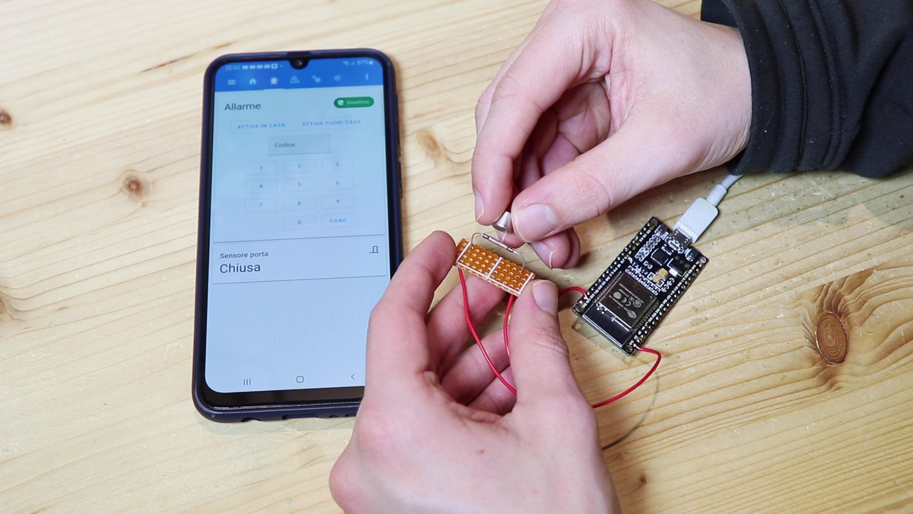

Now that we have loaded the program we can connect the magnetic contact to the ESP32. I soldered the magnetic sensor onto a piece of millefori. Then with two wires I connected the magnetic contact between the 3.3v of the ESP32 and pin 23. Now I have attached the power supply to the ESP32, and on Home Assistant I see that the door is closed or open when I approach or move the magnet away from the sensor.
You will find the schematic of the connections in the pictures above.
Step 3: Connecting the LEDs


Theoretically the sensor for the alarm works and would be fine as it is, but I decided to put LEDs on the sensor. Perhaps having LEDs on an alarm sensor may seem a little strange, but actually in my opinion it is very convenient. In fact these leds can be programmed to signal the status of the alarm and the status of other home automation devices. So for example as we walk out the door we can see right away if we have forgotten a light on in the house, because we will have an LED that signals that.
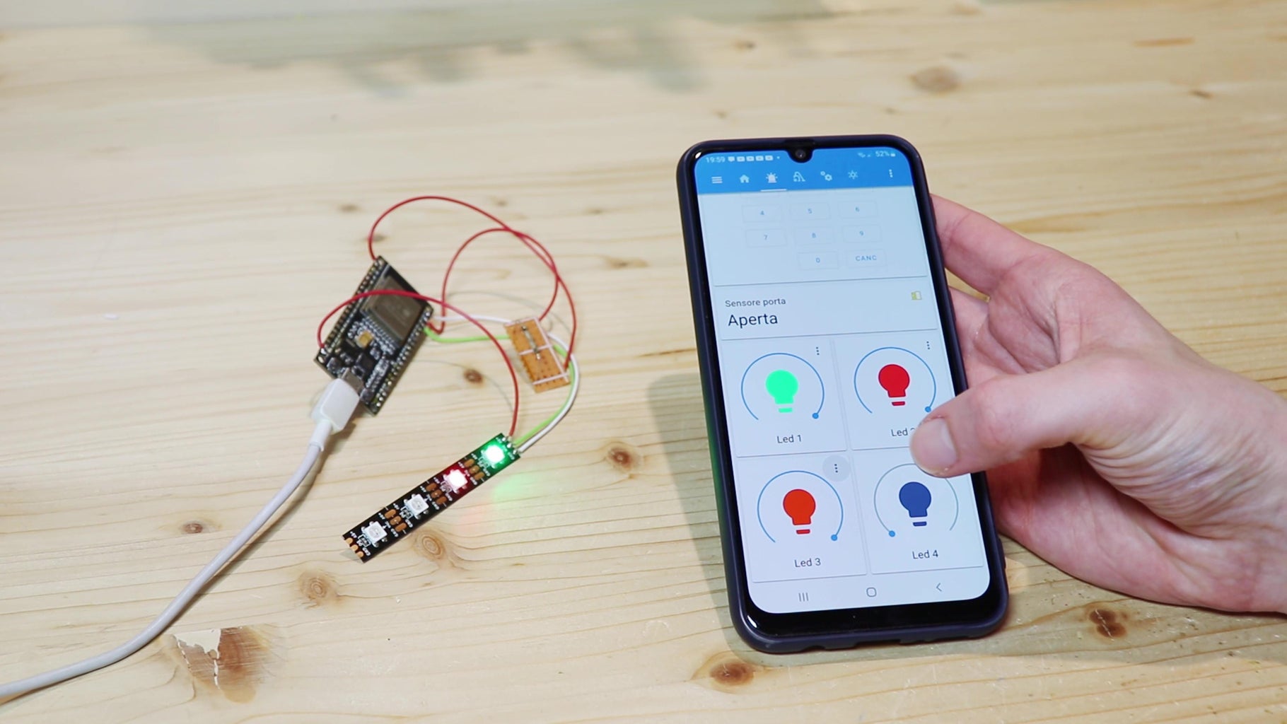
The LEDs I will use to add this function are individually addressable rgb LEDs. These led strips do not have normal rgb LEDs, because you can control the color of each led individually by connecting a single wire for data using an Arduino or similar board. For this project, I cut a piece of 4 LEDs. I soldered three wires to the led strip, two for the power supply and one to the data input, which is marked by the arrow. I connected the power supply of the led strip to 5v and GND of the esp32, and the data to pin 22. So now from Home Assistant I can also turn each of the LEDs on and off, and I can also change the color. Later we will also see how to connect these LEDs to automations.
You will find the schematic of all the connections in the pictures above.
Step 4: Enclosure for the ESP32

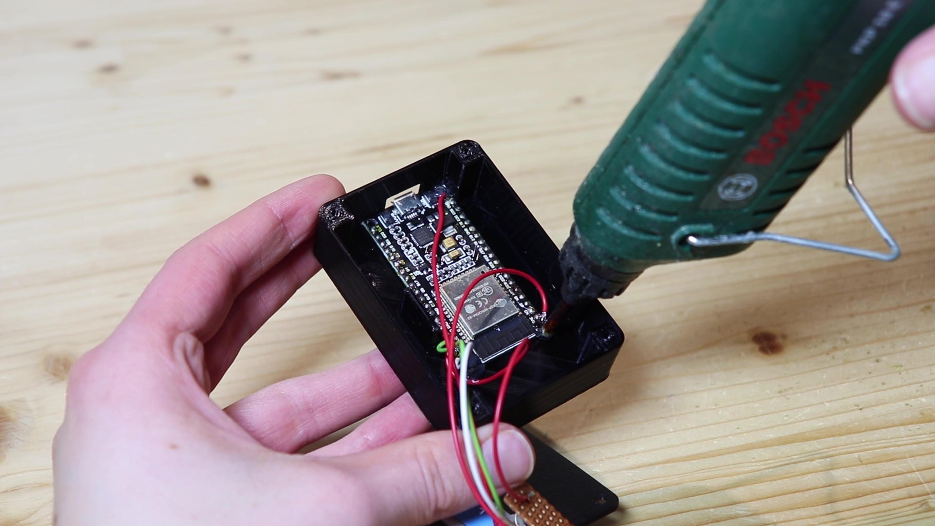
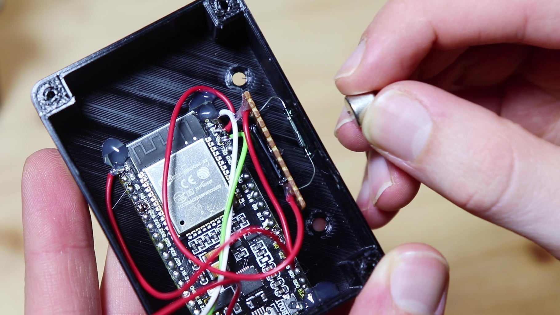


So now the circuit is finished, but it still lacks a box to put it in. So I designed and 3D printed a small box with its lid. The 3D printing files can be downloaded from below. To diffuse the light of the LEDs I will use opaque plexiglass, so I cut a piece and glued it under the hole in the lid of the box. Underneath I put the piece of led strip. Then I put the ESP32 in the box, with the USB port aligned with the hole. I glued the magnetic contact near the wall of the box, so that the magnet could activate it. I closed the box with 4 screws, and we were done.
To power the sensor, I used a USB power supply. Both the door opening sensor and the LEDs work well, so we can mount the sensor on the door.
Smart alarm system


Step 5: Installing the Door Sensor


The sensor will be mounted on the wall next to the door. I used a piece of double-sided tape to mount it. Then I connected the sensor to a nearby outlet with a usb power supply. With another piece of double-sided tape I fixed the magnet on the door, so that when the door is closed the sensor will detect the magnet. And so the sensor works, because on the Home Assistant app I can see if the door is open or closed.
Step 6: "Alarmo" Integration


Now we need to turn the sensor into an actual alarm. To do this I will use Home Assistant's Alarmo integration. This integration allows you to create a real alarm system with the various sensors that are connected to Home Assistant.
To download this integration you can use the Home Assistant Community Store (HACS). Installing it is very easy, as it is using it.
- Once you have opened the integration's settings page, in the General tab you can set the different alarm modes (Armed away, Armed home, Armed vacation) each with its settings
- In each alarm mode you can set the exit and entry delay
- From the Sensors tab you can add to your alarm system different sensors that are connected to Home Assistant; I added the entity of the sensor we have just built
- From the Codes tab you can set different codes to arm/disarm the alarm system assigned to different users
- In the Actions tab you can set to receive notifications on your phone when the alarm is set off, and in the notification you can add the name of the sensor that triggered the alarm, the date and the time - these informations are very useful
- In the Actions tab you can also create some automations based on the status of the alarm (for example turning a siren on), but these don't offer yet a lot of functions
The Alarmo integration also provides a card for the Home Assistant dashboard.
For what I have tested it, this integration is really well done, and it is also very easy to use.
Step 7: Controlling the LEDs


To control the LEDs I put on the sensor you can use the classic Home Assistant automations. For example I chose that the first two LEDs indicate the alarm status with various colors: when the alarm is disermed, the LEDs are blue, when ti is armed they are green, when the alarm is set off the LEDs are flashing red and when the timer after which the alarm activates they are yellow. The different statuses of the alarm are available as conditions in the automations, so making these automations is really easy. The third led turns on when there is at least one light on in the house, so when I go out I can immediately see if I forgot any lights on. For the fourth led, I don't know what automation to create yet, so I ask you: what could the last led be useful for? Write it down in the comments!
Now that we have everything programmed, it's just a matter of trying to see if the alarm works.
Step 8: Testing the Alarm System

Now let's test if the alarm system works as it should.
- I enter the code and activate the alarm, and a 10-second timer starts, allowing me to exit. During this time the LEDs flash yellow.
- After the timer ends the alarm is armed and the LEDs turn green.
- If I open the door and don't turn it off in 10 seconds, the alarm goes off, so it immediately sends me a notification on my phone and is also announced by Alexa. In this case the LEDs turn red and flash.
- When I disable the alarm with the code, the LEDs turn blue.
Step 9: End

So this is my anti-theft alarm system, and it seems to work just fine. I hope you found this guide interesting and maybe useful to make this project. To see the building process, check out the video on my YouTube channel (it in Italian but it has English subtitles). Bye!


![Tim's Mechanical Spider Leg [LU9685-20CU]](https://content.instructables.com/FFB/5R4I/LVKZ6G6R/FFB5R4ILVKZ6G6R.png?auto=webp&crop=1.2%3A1&frame=1&width=306)


