

Introduction: Easy Fingerboard


Skateboarding might be a fair weather sport, but with a small scale fingerboard can be active inside all day long. Though these boards are 1:8 scale, they are 8x the fun!
This easy project would be great to use in the classroom with students in 4th grade onward as a fun challenge that explores STEM concepts including engineering, math, 3D design, and manufacturing. The design can be modified to create more intricate shapes and used to explore new ways to design an already established object. From a STEM perspective, students can learn about design tolerance using a 3D printer, and examine what thresholds work best for allowing parts to fit together snugly and to allow rotation.
This design uses Tinkercad to create a fingerboard that is printed as one piece, without any supports. The wheels are press fit onto the axles and stay locked in place, but still rotate. Here is my fingerboard model, you're welcome to remix this however you like:
Ready to get you skate on? Let's make!
Step 1: Making the Deck
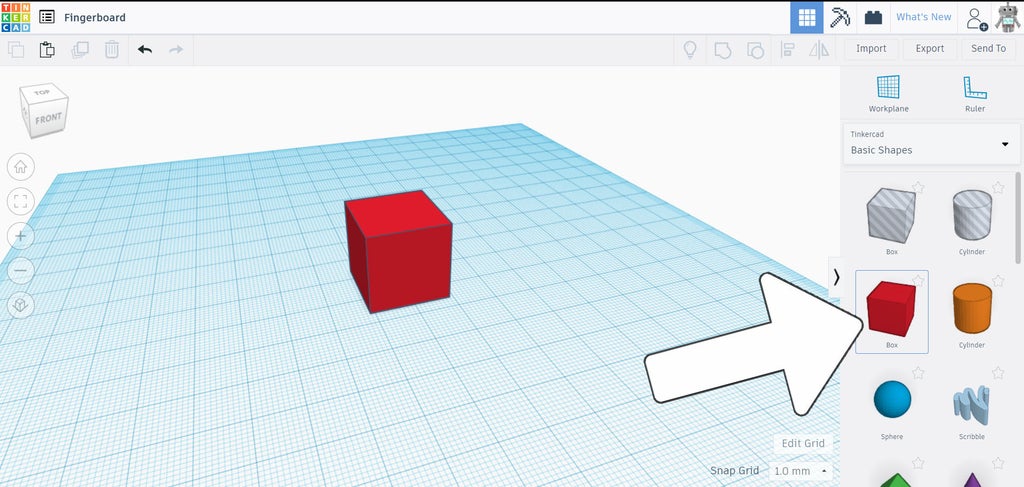
Begin by opening a new design in Tinkercad.
To start making the deck a box was dragged from the sidebar onto the workplane.
Once placed the shape can be clicked and values can be input for the dimensions of the deck, in our case we're making the deck on it's side so we'll use 60mm x 2mm (length and depth of deck).
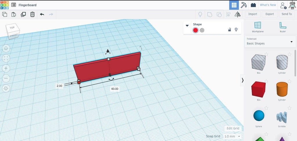
The actual dimensions aren't important, since we can resize or scale the board later to suit our needs.
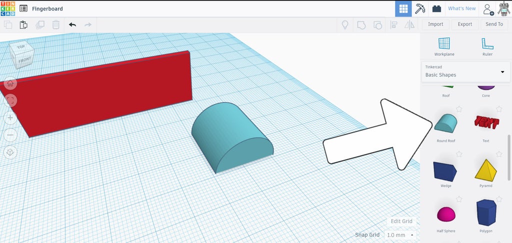
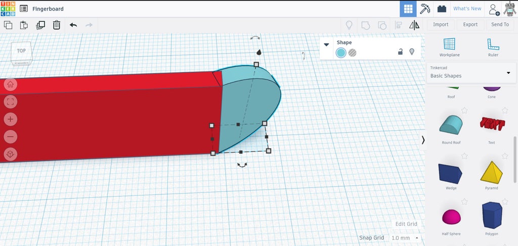
Next, a rounded roof shape was dragged from the library and onto the workplane.
This will be the inclined kick of the deck. We'll resize this by clicking on it and reducing the depth to 2mm to match the deck we placed earlier.
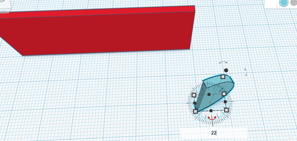
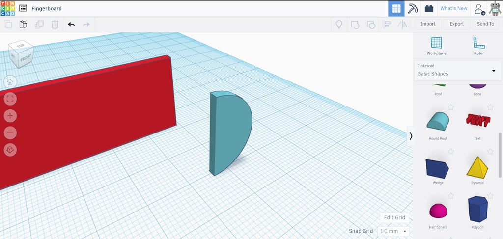
The shape can be rotated by clicking on the piece and locating the semicircle arrows near the selected shape. There are 3 different arrows corresponding to the axis on which it can rotate. Since our board is being built sideways we want to rotate around the Z axis, which will b located on the bottom of the shape on the workplane.
Click and hold on the semicircular arrows and move your mouse to rotate the piece around that axis. You can also input an exact rotation in degrees by using the text box to put in an angle. I used 22°.
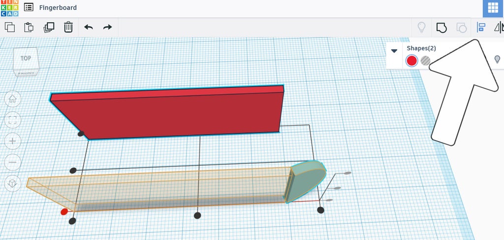
To line up the two shapes you can drag either of them towards the other, but to get really precise we can use the align tool from the top navigation bar. Select both shapes and then click the align icon. There will be an overlay that appears on the workplane with handles at the ends and middle of each work plane. We want both pieces to be aligned along their bottoms, so use the handle closest to you (shown in red above) to move both pieces to be bottom aligned.
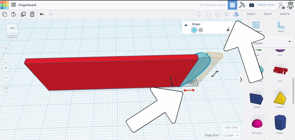
After they are aligned along the bottom, click anywhere to stop the align. next step is to move the two pieces together laterally so that the rotated rounded roof shape overlaps the rectangle. Select the rounded roof and drag towards the rectangle while holding shift, which will constrain the movement along one axis. move the rounded roof until the end is completely inside the rectangle.
The the basic board shape is complete! We can work on the details, now.
Step 2: Symmetry
We could repeat the same steps to create the kick for the other end of the board, but I think making a copy is easier.
Select the kick from one end of the board and duplicate (ctrl+d), then use the flip command from the top toolbar.
Arrows will appear on the workplane indicating which direction the selected object will be flipped. As shown in red above, flip along the axis to create a mirror of the kick.
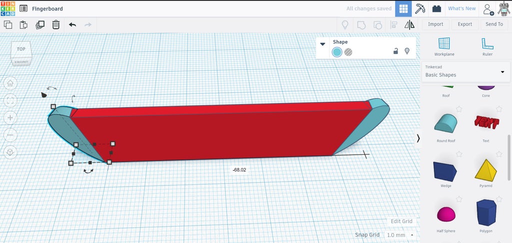
This mirror shape can now be moved to the other side of the board. You may input the measurement (I used -66.02mm) or use the shift key to constrain the movement along the lateral axis to the other end of the board.
Select all 3 shapes (kick, deck, and other kick) and group (ctrl+g) to combine the shapes into one piece.
Step 3: Axle
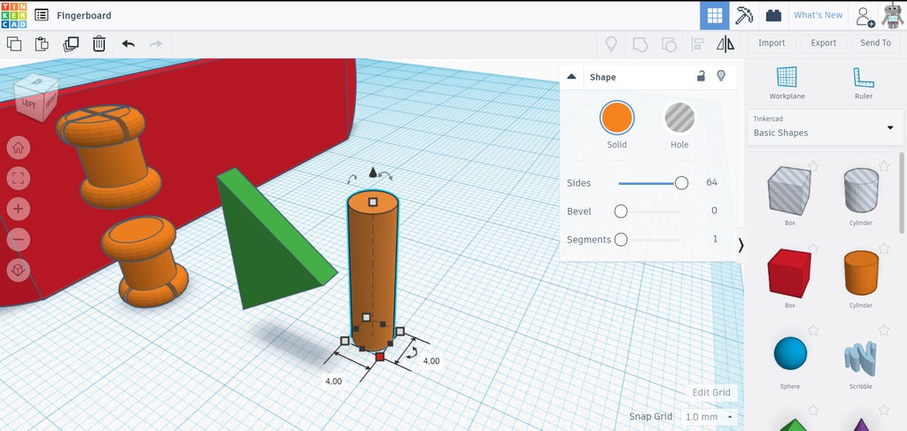
The trucks are the most technical part of this build, but by breaking it down into smaller parts it's easily manageable. Start by dragging a cylinder from the library to the workplane. There is a modifier menu that pops up for some shapes that allows changes to the parameters of the selected object. The cylinder is one of those shapes.
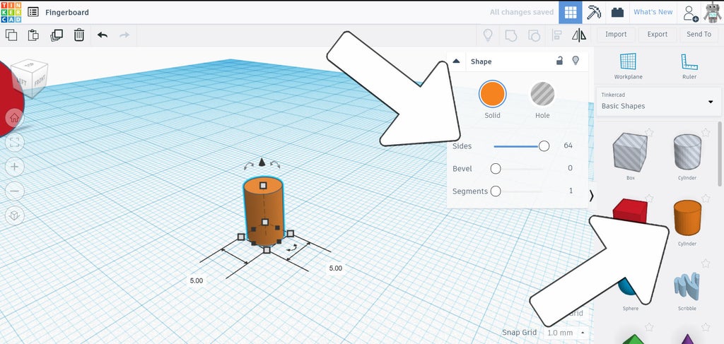
The menu for this shape has sliders that can be moved to refine the shape parameters. We want to move the sides slider all the way up to maximum, this will give the cylinder smooth sides. Change the diameter of the cylinder to 5mmx5mm.
Next, find the torus from the library and drag that onto the workplane. Using the same menu, the torus can be modified to have more sides which will make the shape smooth. Change the diameter of the torus to 7mmx7mm.
The cylinder shape will be the axle that the wheels ride on, and the torus will be the edge that keeps the wheel on the axle.

Now, drag a box hole from the library onto the workplane. We'll use this hole shape to create relief openings in the axle that will allow the wheel to slip on and stay in place.
Resize the box shape to 0.5mmx8mm, with a height of 2mm.
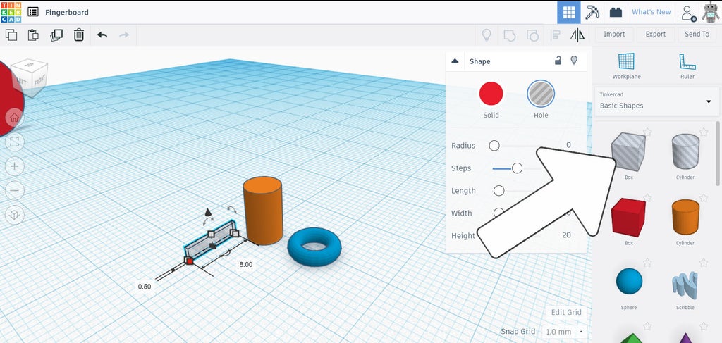
Make a duplicate of the box hole and rotate the copy 90°, making an X shape.
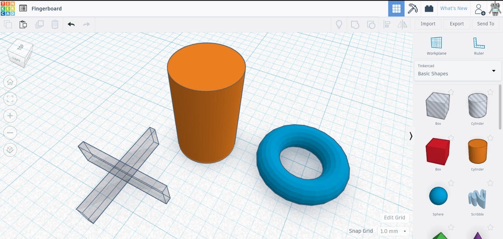
Above, these basic shapes are what are used to make the axle for the wheels.
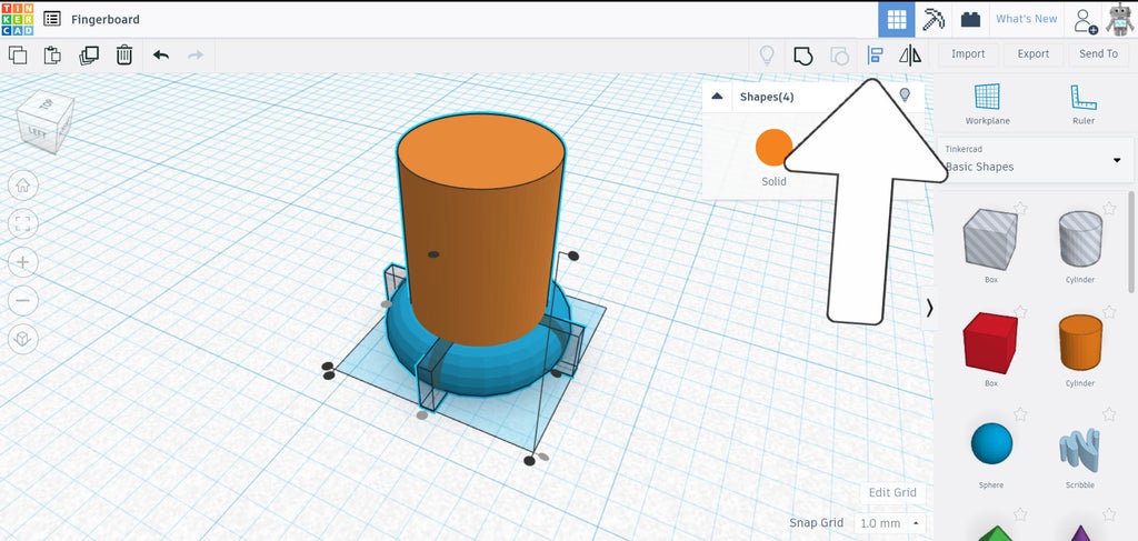
Select all 4 shapes (2 boxes in X configuration, torus, and cylinder) and align them in the center by using the middle handles on the workplane.
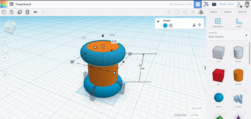
With all the shapes aligned and centered, make a duplicate of the torus, then move the duplicate upwards, this will be the channel the wheels will ride inside. I show 6mm here, but this can be any size to match your wheel width. Select everything and group to create the axle.
This is one side of an axle for our skateboard. Next, we'll duplicate this to create the corresponding axle on the other side.
Step 4: Duplicate Axle + Make Trucks
Select the grouped axle and duplicate, then mirror the copy and move upwards. The relief cuts should be facing outwards.
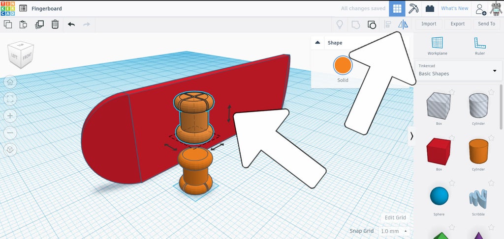
Before joining the two axles into one we can start the truck design. Find the roof shape in the library and dag it onto the workplane.
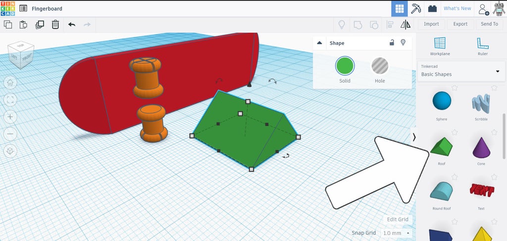
Rotate and resize the roof shape into a flat triangle prism shape, about 4mm thick.
Grab a cylinder from the library and drag it to the workplane, smooth out the sides using the slider, then resize the diameter to 4mmx4mm.
The cylinder and the tip of the triangle prism we aligned and then moved so the tip was almost poking out the cylinder (shown below).
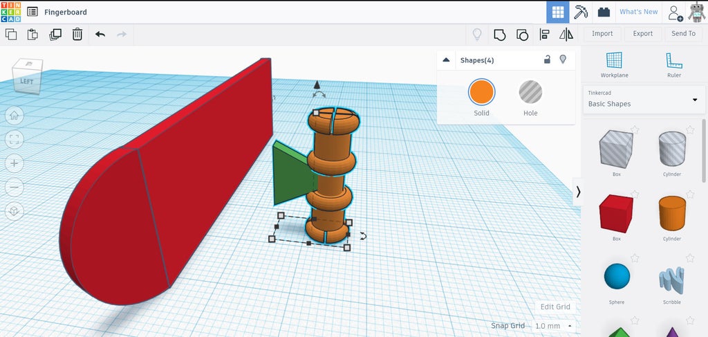
The cylinder and triangle prism can be aligned with the two wheel axles. Select the axles, cylinder, and triangle prism and group to create the truck assembly.
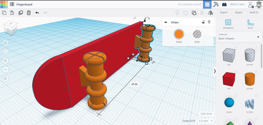
Move the truck assembly so the wide end of the triangle prism is inside the deck, then duplicate the truck and move the copy (using shift to constrain the axis of motion) to the other end of the deck.
The construction of the board is nearly complete! If you're unhappy with any elements of the design so far you can select the shape you want to modify and ungroup. Then, once changes are made, group again.
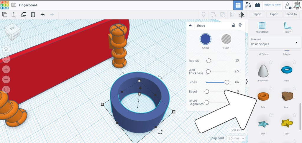
Step 5: Wheels
There's a few ways to make 3D printed wheels, but I like using the tube shape. Dragging a tube onto the workplane brings up the modify menu where you can change the interior and exterior diameters of the tube shape to suit your design.
An alternative to this approach would be using a cylinder with a smaller hole cylinder inside it to create the wheel shape. Either works here.
Copy the wheel 3 more times to get 4 wheels total.
Step 6: Export + Print
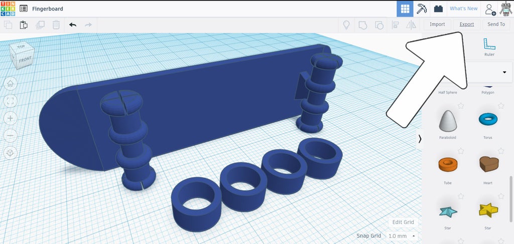
With everything grouped together, select all and export using the icon in the top right. For 3D printing export as .STL.

The reasons the board was deigned sideways is so that it can be printed without using any support structure. Support is used in areas of overhang when 3D printing, which allows areas that are suspended above the print bed with nothing underneath it something to rest on when printing starts. Printing without support material is preferred as there is no cleanup after the print is done.
This design prints without any supports, but you may need to tweak your printed settings to dial in this print.
Step 7: Add Wheels

The tolerance between the axle diameter and the interior diameter of the wheel is enough to allow the wheels to spin freely, and the relief cuts on the end of the axles allow the wheels to be pushed on and then spring back into shape to hold the wheels on.
Step 8: Skate!
While finger shoes and finger pants are optional, they definitely add to the effect.

Have you made you own fingerboard? I want to see it!
Share a picture of your creation in the comments below.
Happy making :)

Participated in the
Classroom Science Contest


