

Introduction: Equidistant Layout Divider


It might be specialized, but a layout divider is a tool you might find yourself reaching for once you have one handy. There's times in the shop when I have an arbitrary length to a piece and I need to split the difference. Instead of measuring out the distance and doing division, this handy tool articulates to whatever distance you need and creates an even spacing between each joint.
It might seem complicated, but I was able to design this in Tinkercad, a browser-based CAD software that's easy to use and completely free! The parts were then cut out on a laser cutter.
DISCLOSURE
Dremel was kind enough to loan me a laser to try out and see what projects I could come up with using Tinkercad. You can find out more about Dremel's new laser cutter and get a hefty discount here (discount ends September 30, 2018).
Here's the layout divider in action

Though certainly not a precision tool when made out of plywood, it can serve as a great reference tool when "close enough" is all that's needed.
You can explore my design below, in the ebedded Tinkercad interface
The SVG file is available at the end of this step
Ready? Let's make!

Step 1: Reference

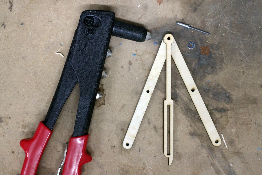
Before any designing there's a reference measurement that needs to be taken. I used rivets as the pins that allow articulation and hold the parts together,. I needed to measure the diameter of the rivet head so I could use that in my design.
Step 2: Basic Shapes
I used Tinkercad to design all the parts for this. Tinkercad is a browser based design tool, and it's completely free!
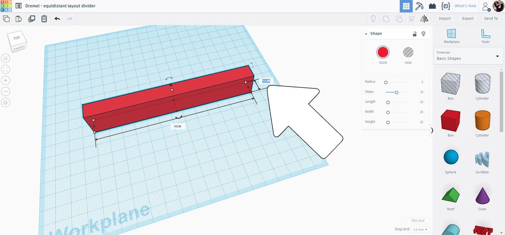
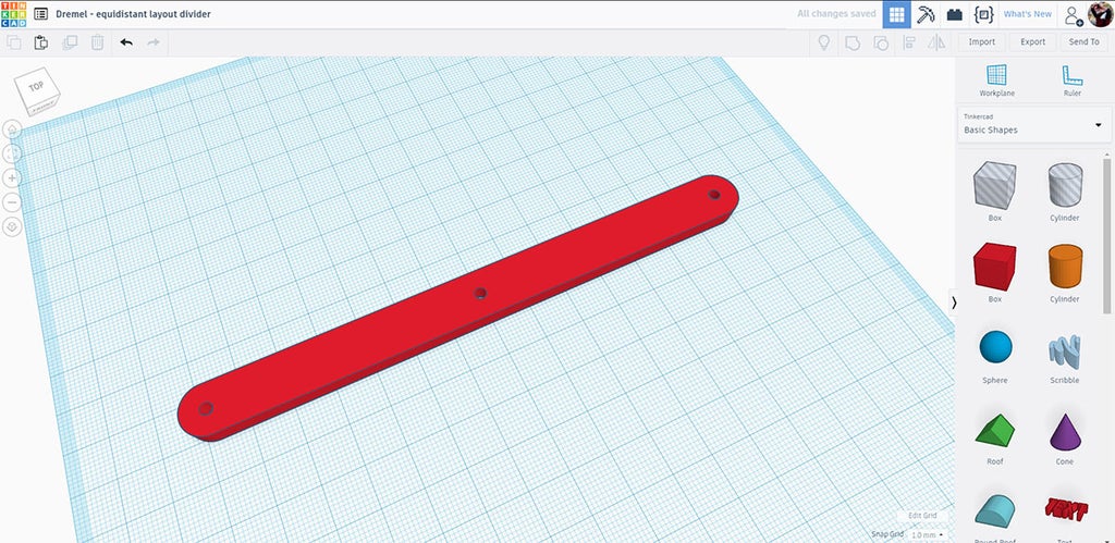
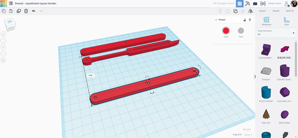
Start a new design in Tinkercad and drag in a box to start
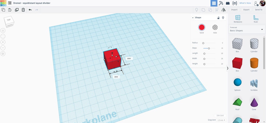
With the shape selected there are handles on each corner and ends that allow you to pull to stretch the shape. There are text boxes on each side that allow you to manually input a dimension. I have this design at 12mm wide and 133mm long. Since I'll be cutting these out on a laser there is not height requirement so I put the height at 5mm, that allows a close approximation to how the design will look when it's cut out.
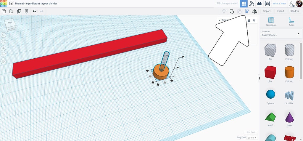
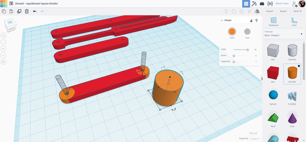
To make the ends of the arms I used two cylinders, one solid and one a hole. The hole was made to be the same diameter as the rivet head I had previously measured, the solid cylinder was scaled to match the width of the rectangle shape, 12mm.
With both cylinders were selected I used the align command from the top toolbar to align the two shapes on top of each other and centered.
These cylinders will be moved to the end of the rectangle and them copied to make the end caps.
Step 3: Starting Articulation Arm
The two nested cylinders were moved towards the end of the rectangle, but placed offset from the end. The cylinders and the rectangle were then all selected and the align tool was used to bring them all in line.
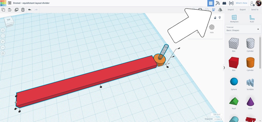
To get the cylinders into the right location I used the workplane tool, which allows for a new workplane to be placed anywhere, which will then allow other shapes to be moved with accuracy in relation to the new workplane. It sounds complicated, but is actually really easy when you see it in action.
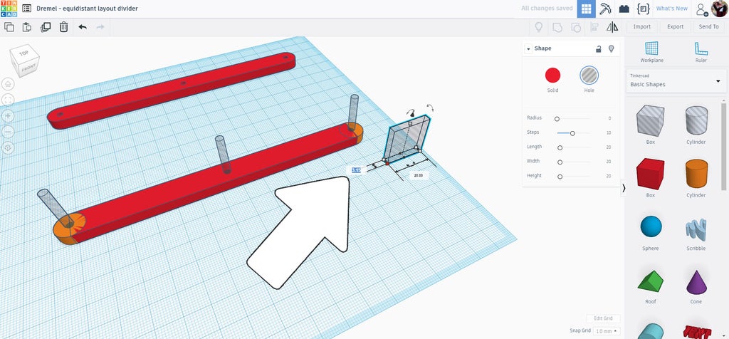
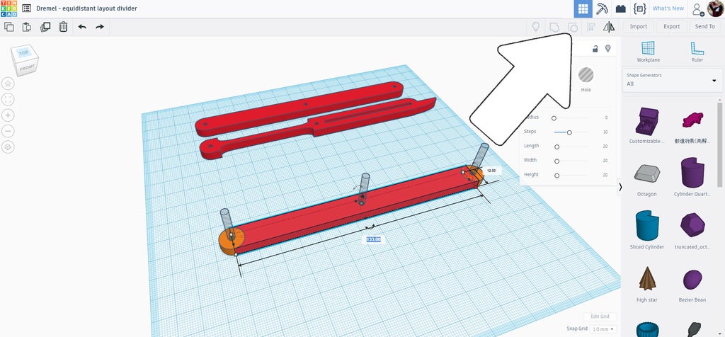
Find the workplane on the right side toolbar, click it and then hover your mouse over the end of the rectangle - you should see an orange box which indicates where the new workplane will be. When the workplane box is vertical and on the end of the rectangle click the mouse to accept the location.
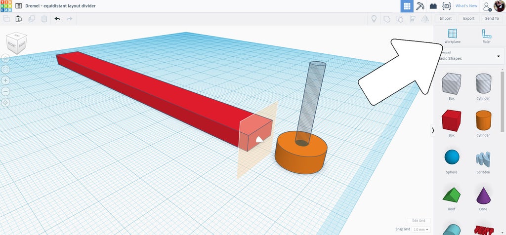
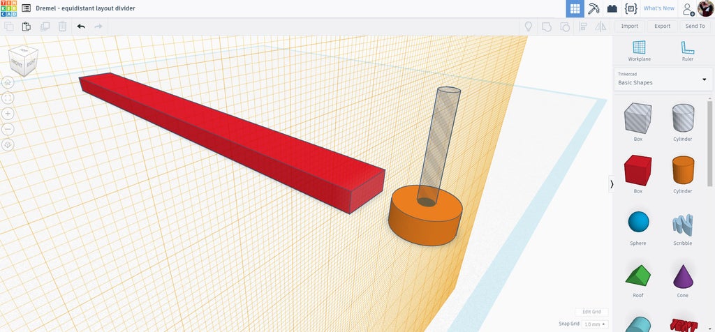
There is now a temporary workplane on the end of the rectangle that will allow us to move the cylinders against it.
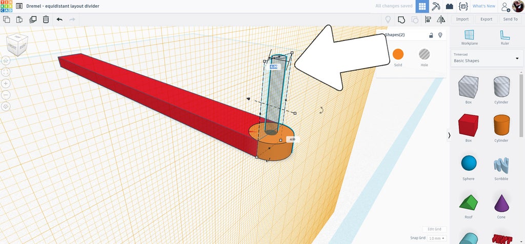
Select both cylinders and drag them towards the workplane, you will notice a text box appear that gives a readout of how far away the cylinder is from the workplane. You can continue dragging until that value is 0, or you can enter the value manually and the pieces will automatically move there.
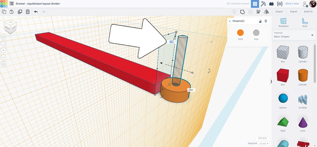
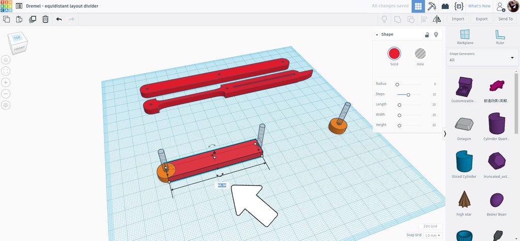
Now that the large cylinder edge it touching the end of the rectangle we can position it exactly where we need. We want the center of the cylinder to be right on the end of the rectangle. We know that the diameter of the large cylinder is 12mm, so to get it centered on the end of the rectangle we need to move it 6mm. As before, you can drag or manually input the value to get the shapes to move.
When the cylinders are in position chose workplane again from the right side toolbar and then click anywhere there is white space /blank space on the screen to reset the original workplane.
Step 4: Complete Articulation Arm
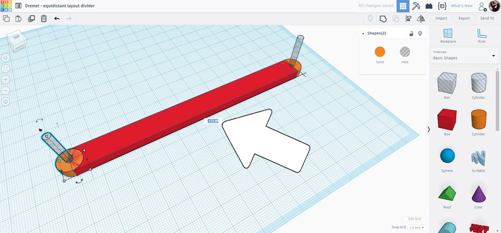
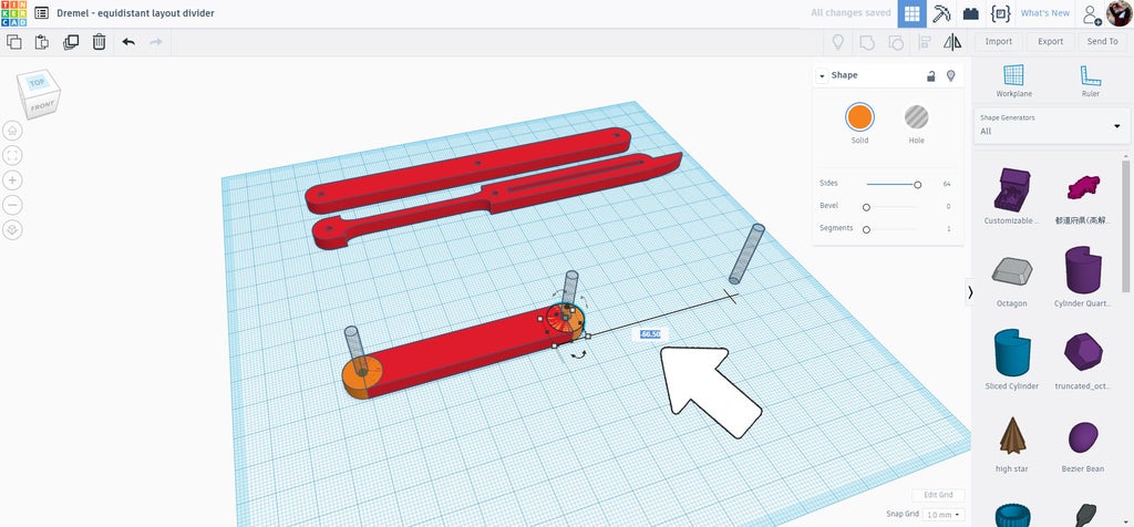
To get the same result on the other end both cylinders are selected and then duplicated (ctrl+D). Then drag them towards the other end. While moving the text box shows the distance moved, since we know the length f the rectangle is 133mm we can manually input that value to move the pieces to the other end.
Select all the pieces and then group together using the group tool on the top toolbar or ctrl+G. I made a new cylinder hole the same diameter as before, as this will be the pivot point for the articulating parts.
Select the grouped rectangle and the cylinder hole and align the two so they are centered.
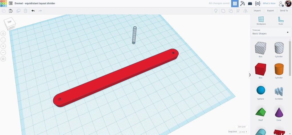
Group the pieces together. You now have the articulating arm finished, this piece is the most common piece in the assembly.
This piece will be used to create the other pieces in the design. move this completed piece out of the way for now.
Step 5: Pointer
Make a duplicate of the arm you ust made by selecting it and duplicate (ctrl+D). Move the duplicate towards the center of the workplane then ungroup from the top toolbar, or use ctrl+U.
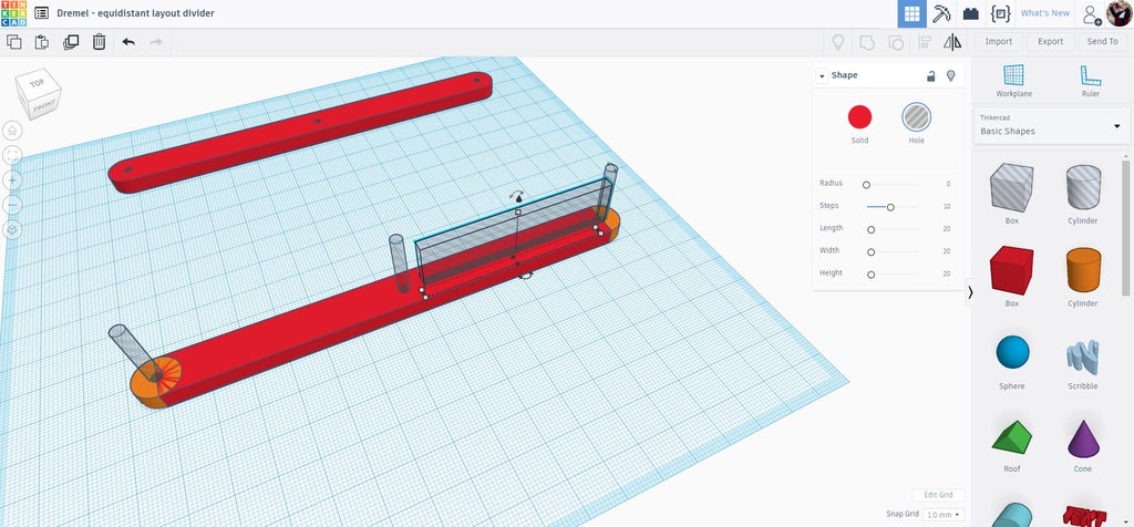
Drag a new hole box onto the workplane and change the width of the box to the same as the rivet head, then use the align tool to bring the rectangle hole in line with the ungrouped pieces.
Drag the box hole until it's over one end of the rectangle on top of the hole cylinder. The box hole can then be stretched until it almost reaches the center of the elongated rectangle. This will be the guideway where a rivet head will slide when the layout divider is opened.
To make room for the rivet heads when the layout divider is closed there needs to be some material removed from the opposite end of the piece. I used a box hole to make a cutout - any shape will work here since we're only removing material. The box hole was placed offset from the center of the rectangle, then duplicated and placed on the other side of the rectangle to make the cutouts even.
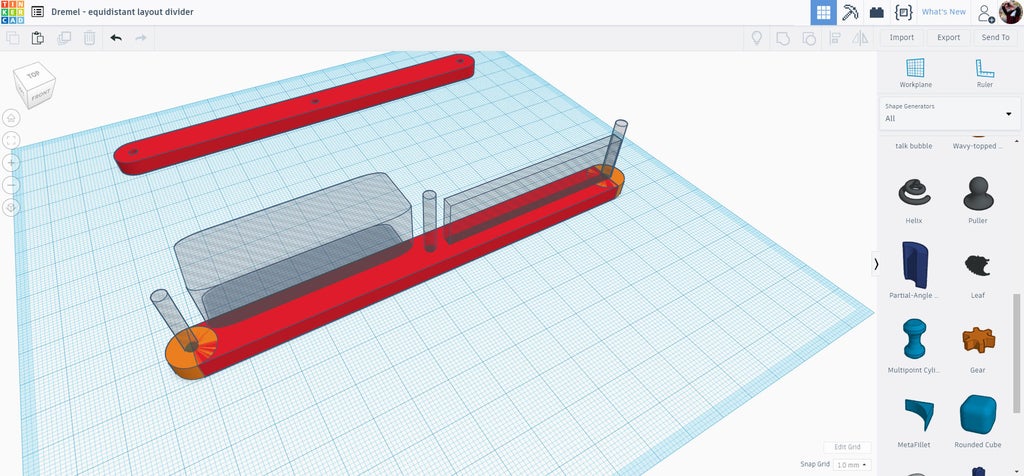
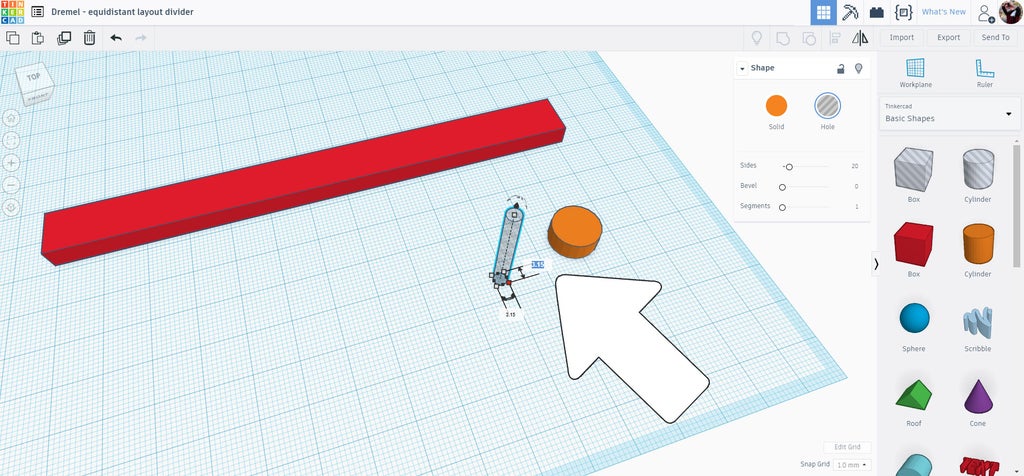
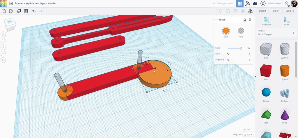
The pointer at the tip I made from a sliced pie shape I found under the Shape Generators dropdown library on the right side of the screen. Drag a sliced pie onto the workplane.
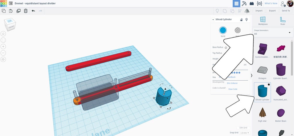
With the sliced pie selected there is a variety of options on how to edit the shape. I changed the arc of the pie to 180 degrees, then stretched the pie shape to elongate it and make it more of a pointer.
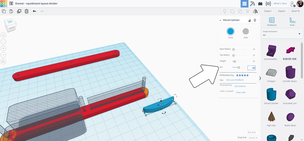
The pointer pie shape was moved and aligned with the rest of the pointer pieces.
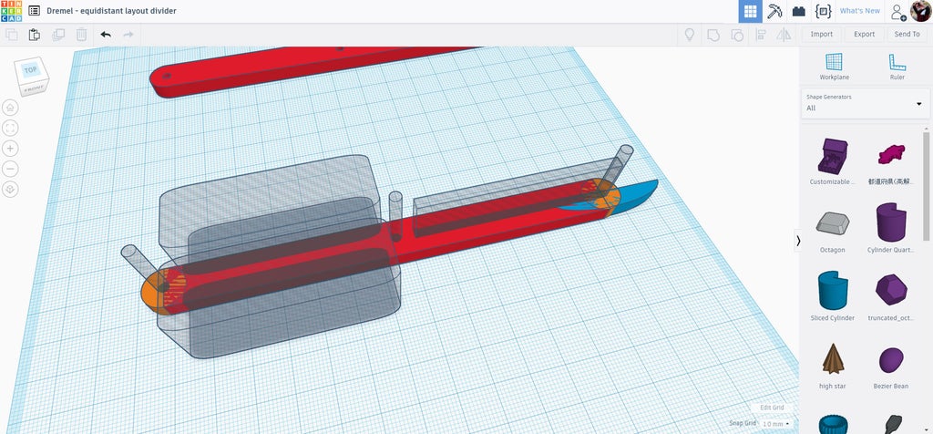
Select all the elements of this pointer piece and group (ctrl+G) to finalize the shape.
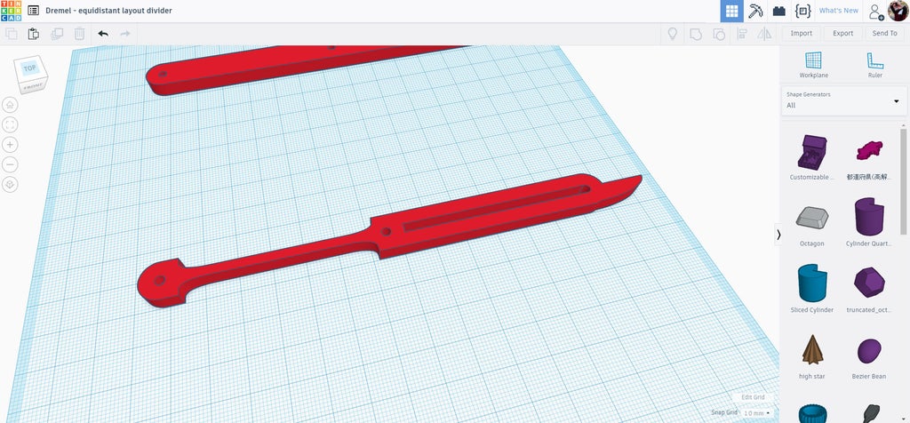
This is a completed pointer piece. Move the pointer out of the way and we can work on the final piece for the layout divider.
Step 6: End Piece + Handle
Select the original articulating arm and make a duplicate (ctrl+D), then drag the copy to the center of the workplane.
Ungroup the copy to reveal the individual parts.
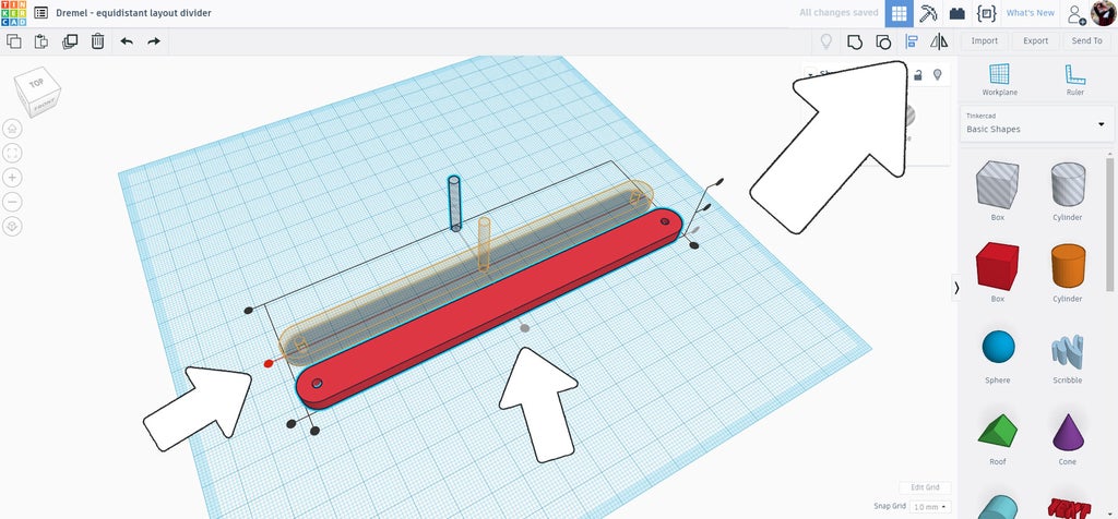
Grab the end of the rectangle piece and bring it towards the middle, halving the original length.
Select the orphaned solid cylinder and move it to the central hole cylinder to complete the end piece.
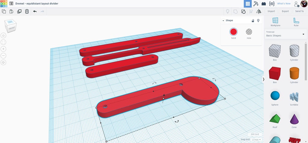
A new cylinder was dragged onto the workplane and flattened to match the other components.
The cylinder was positioned towards one end, ensuring the bulge of the cylinder only protrudes from one side.
Group the elements together and the end piece and handle is complete.
d
Step 7: Export
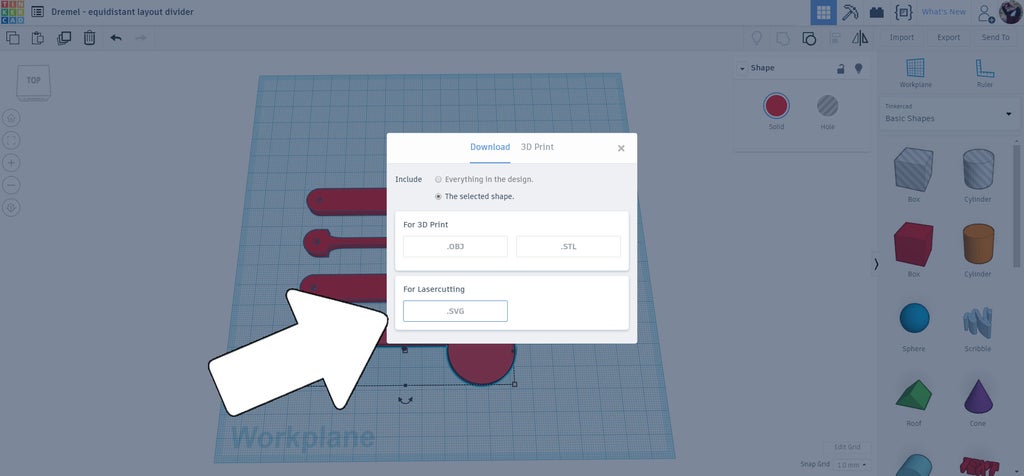
With the 4 components complete each can be exported separately. Be exporting them one at a time you will have control over how many of each you will cut out on your laser.
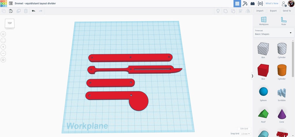
Select one of the components and export as an SVG file. Repeat for all components.
Step 8: Laser Time!
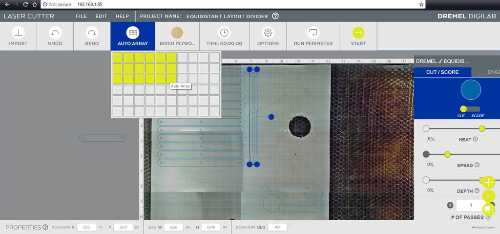
The Dremel laser can take a picture of whatever you load into the machine, this allows you to accurately place your files wherever your material is without worrying about if it will fit. You'll be able to see where to best place your files. Load in each file into the Dremel interface. Once loaded in you can drag items around the screen to position them.
A great function the Dremel editor has is the array tool, allowing multiples to be quickly and accurately placed and spaced to minimize waste. I needed 2 handle pieces, 2 end pieces, 7 pointer pieces, and 12 articulating pieces. The array tool made quick work of the placement and I was ready to start cutting.
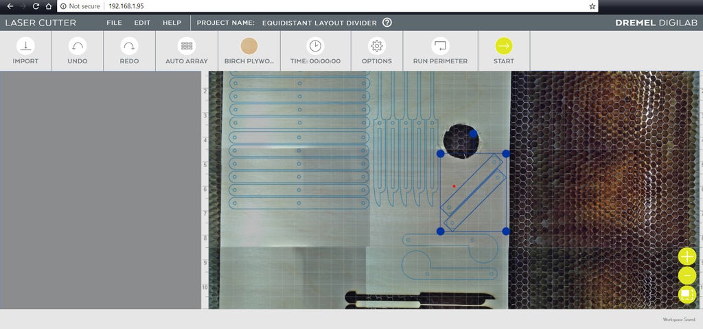
Pieces that went off the material I had in the machine could be easily dragged to a better placement, and even rotated to maximize the nesting of parts to be cut.
Step 9: Rivets

I used pop rivets to hold this layout divider together, with washers on either side of the rivet to help keep it seated. Instead crimping the rivet until it pops I loosely crimped the rivet to deform the end and prevent it from escaping through the washer opening. By loosely tightening the rivets instead of crimping them allows the layout divider to articulate and move.
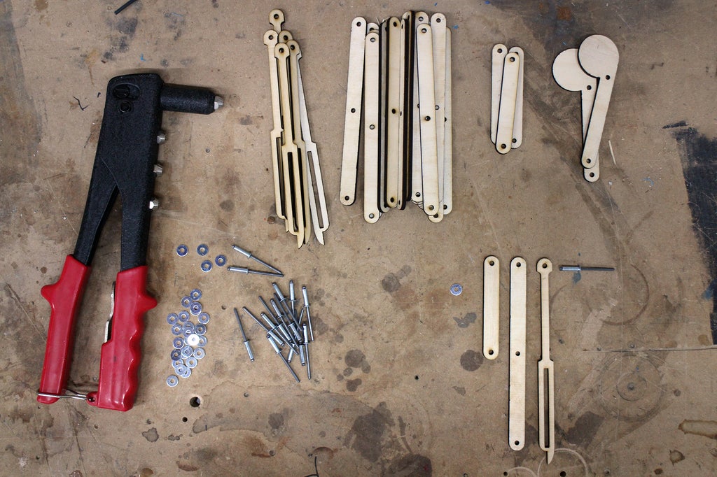
I'm using an inexpensive riveter and common rivets. I set up the components so that the two articulating arms had a common end stacked on top of each other, then a pointer piece was placed on top - aligning the openings on one side when they are stacked. A rivet was inserted into the common opening and a washed places on top.
To keep things consistent I set up as many of these as possible before moving on. The rivet was then set inside the riveter and the handle squeezed to mushroom the top of the rivet, ensuring nt to squeeze too tightly and seize the movement between the pieces.
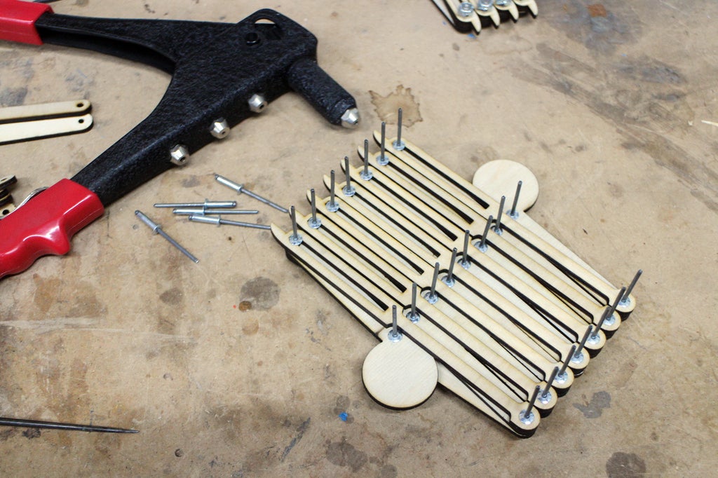
This step was repeated until all pointer pieces were attached to a pair or articulating arms, checking the movement action on each one to ensure they could operate freely. The riveted pieces were then lined up next to each other and more articulating arms were added to connect the riveted pieces which were then riveted together in the same fashion.
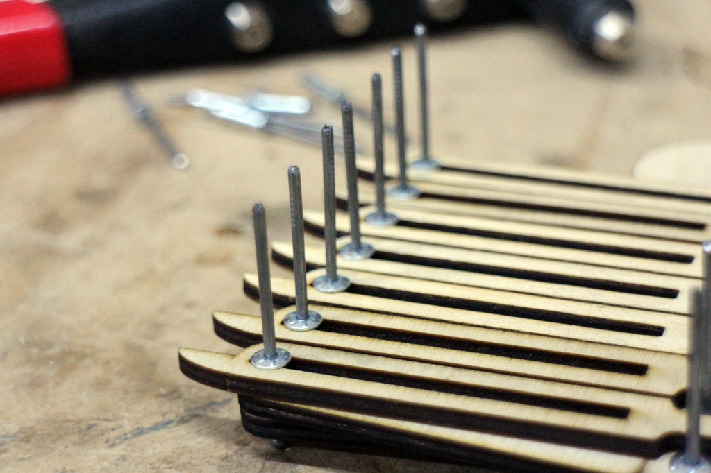
Above is a close up of the rivets with the tails still attached, since they were not squeezed enough to make the rivet pop.
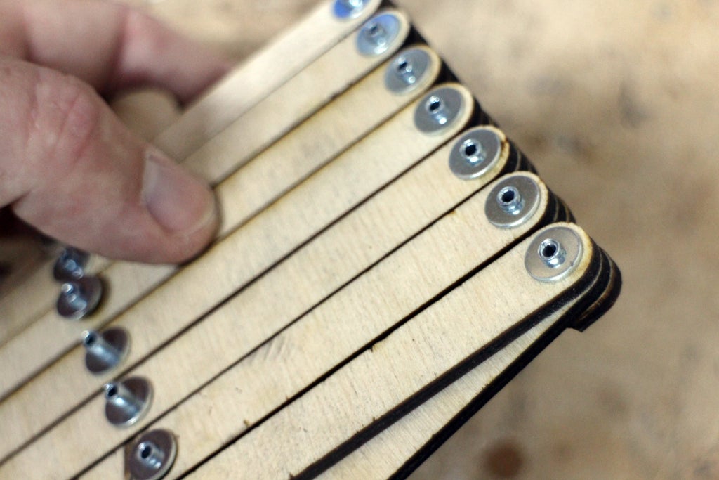
Above is a close up of the mushroomed tops of the rivets that were gently squeezed.
Step 10: Cut Rivet Tails

The rivet tails usually fall off once a rivet is popped, but since we were only gently squeezing these rivets the tails need to be cut off in order to be removed.
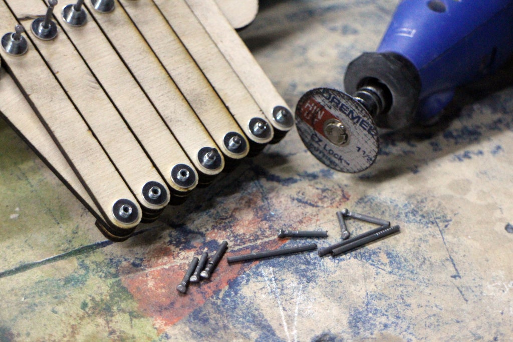
I used a rotary tool with a cutoff wheel to slice the tails off, the remainder of the rivet tail will either fall off or can be pulled through the rivet leaving just the low profile rivet head.
Step 11: Start Dividing!

Your layout divider is now ready to start segmenting your spaces, however you need them split up. Sure, the action might not be completely accurate but it will be close enough, and it sure beats doing the math for quick dividing tasks.
This is a useful tool, or an educational toy. However you use it, there's endless fun from opening and closing the articulating parts and watching the mesmerizing parts move.
Have you made your own layout divider or been inspired by this project? I want to see it! Share a picture of your creation in the comments below.
Happy making! :)

![Tim's Mechanical Spider Leg [LU9685-20CU]](https://content.instructables.com/FFB/5R4I/LVKZ6G6R/FFB5R4ILVKZ6G6R.png?auto=webp&crop=1.2%3A1&frame=1&width=306)


