

Introduction: Hi-5 Collector Circuit


In this lesson, you will build the final circuit for the Hi-5 Collector project and upload the final sketch. The final circuit is a simple one you have already built during the Digital Input and Digital Output lessons. The sketch uses code that you have already used and introduces two new elements we will go over.
You will learn:
+ how to store button presses
+ ways to record a completed circuit
Step 1: Materials

+ microcontroller
+ USB cord
+ alligator leads
+ 1 x sewable LED
+ LiPo Battery
+ handmade switch
+ paper
+ pen
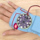
Step 2: Build Circuit

Connect the circuit as illustrated.
handmade switch --> pin 2
handmade switch --> ground (-)
LED power (+) --> pin 3
LED ground (-) --> ground (-)
Step 3: Upload

Download the attached sketch and upload it to your board. The LED will blink twice then stay on. This means that the sketch has loaded and is running.
How Does it Work?
When the sketch loads and is running the switch listens to see if there are any switch presses. Open the serial monitor to watch the switch presses.
Go ahead and press your switch! The LED will go off and that one press will be recorded in the software. Press the switch four more times and the LED will go on, indicating you have reached five presses. Press it another five times, it will go off and come back on when you reach 10. This is how it collects high-fives, it records how many times the button has been pressed and lets you know what you have reached your goal.
Put the switch on and give a high-five to test it out!
Attachments

Step 4: The Code
Variables are created to hold the number of times the switch is pressed, the current state of the switch (on/off) and one to hold the previous state of the switch. The previous state gets stored because it is compared to the current state later in the sketch.
int buttonPushCounter = 0;
int buttonState = 0;
int lastButtonState = 0;
This is where the previous state of the switch gets compared to the current state. The != characters mean not equal to. If the buttonState variable value (1 or 0) is not equal to the lastButtonState, check to see if it's LOW (0/pressed). If it's LOW, increment the count of switch presses (high-fives) and store it in the variable buttonPushCounter. The block of code that gets executed also prints the current value of the buttonPushCounter, so you can see it's progression.
 if (buttonState != lastButtonState) {
    if (buttonState == LOW) {
      // if the current state is LOW then the button
      // went from off to on.
      // if the state has changed, increment the counter
      buttonPushCounter++;
      //print that the button is pressed/on
      Serial.println("on");
      //print the number of pushes you are on
      Serial.print("number of button pushes:  ");
      Serial.println(buttonPushCounter);
    }
The modulo - %, divides one number by another number and leaves the remainder. Here it is dividing the buttonPushCounter variable value by five and asking if the remainder equals zero. The remainder will only equal zero when the value of buttonPushCounter is zero or a number evenly divisible by 5, like 5 ,10, 25, etc. If the division of the buttonPushCounter by five equals zero, the LED goes HIGH and turns on. If it does not equal zero, the LED is LOW and remains off. Try changing the five to a higher number to collect more high-fives.
if (buttonPushCounter % 5 == 1) {
    digitalWrite(ledPin, HIGH);
  } else {
    digitalWrite(ledPin, LOW);
  }
Step 5: Make It Mobile

When plugged into the computer through USB, the LilyPad board receives power. To power the board while it's not connected to the computer you use the LiPo battery.
Unplug the USB cord from the board and grab your LiPo battery and plug it into the JST connector on the board. Push the switch towards ON to power the board. Your project is now mobile and can go anywhere! To charge the LiPo battery, keep the board connected to the computer via USB and push the switch towards CHG.
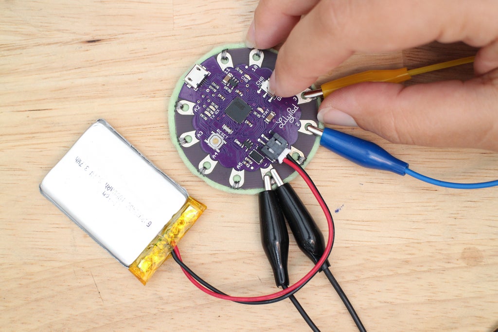

Give a high-five or clap your hands 5 times to see the LED light up. Snap a photo of your switch working with a battery and upload it below!
Step 6: Record Connections

After the final circuit is built and tested with the sketch it is ready to transfer onto fabric. To do this, the circuit needs to be unclipped and taken apart. To know how to put the circuit back together it needs to be recorded. There are three ways you can do this that I will briefly go over now:
1) Draw a schematic diagram. I find this to be a fun process because learning how to read schematics is like learning how to decode secret messages coupled with reading a map. In a schematic diagram, each electrical component is represented by a graphic symbol. Check out this instructable of How to Read Circuit Diagrams for an introduction to schematic symbols. The Electronic Symbol page on Wikipedia is also a good place to start.
2) Create your own drawing. Use a pencil or computer to create a diagram of your own making. Mark the pin numbers on the microcontroller and the power and ground of each component. Draw in the traces and you have your own roadmap of which to rebuild your circuit by.
3) Write it down. For simple circuits, you can write down each connection line-by-line. For example:
high-five switch --> pin 2 of LilyPad
high-five switch --> ground of LilyPad
No matter what method you go with, always double check the recording to make sure you wrote the connections down correctly. How did you record your circuit? Share a photo of your diagram below!
Step 7: Disconnect

Once you have recorded the circuit, you are ready to safely take the circuit off the alligator leads. After you disconnect everything, you will have four components:
1 x LiPo battery
1 x LilyPad USB
1 x sewable LED
1 x handmade switch
Share your final circuit clipped together and in action below along with your diagram. In the next step, we will build the accessory this circuit will be sewn to!


![Tim's Mechanical Spider Leg [LU9685-20CU]](https://content.instructables.com/FFB/5R4I/LVKZ6G6R/FFB5R4ILVKZ6G6R.png?auto=webp&crop=1.2%3A1&frame=1&width=306)


