

Introduction: Home Assistant/ESPHome LED Matrix Temperature and Power Meter


There are many ways to extend HomeAssistant, and one very interesting area (in my opinion) is the ability to connect various displays to show vital data around the house. This article describes how to build your own ESPHome-based LED matrix temperature and electric power meter. It requires an existing Home Assistant system, with the ESPHome add-on installed.
If you follow this article, it will display outdoor temperature and current power produced from a solar cell installation. If you want other measures to be displayed, you can easily customize it to show any data that exists in your Home Assistant system.
There is a button that can be used to switch between the different data sources, or you can also make it toggle between the data sources automatically by adjusting the code.
New: If you long-press the button, you can change the intensity of the LED matrix in 16 steps, each press increases the intensity until you reach 15 and then it starts over at 0. Long-press again to leave the intensity setting mode.
The case is 3D-printed and you can either use the ready-to-print STL files, or adapt the source file (made with Fusion 360) for your own needs.
Supplies
You will need the following items:
- Lolin/Wemos D1 Mini Pro (or similar ESP8266 or ESP32 microcontroller that works with ESPHome)
- MAX7219 LED Dot Matrix module 8x32 dots
- PCB-mounted push button with cap
- Small piece of veroboard/stripboard with standard 0.1" pitch, to mount the push button on
- 5V power supply, any USB charger will do fine.
Some links:
Step 1: Setup Microcontroller With ESPHome
Visit https://web.esphome.io to setup the D1 Mini Pro (or whatever microcontroller you want to use). Give it a name that describes the function, in my case it's called "solar-wattmeter".
Once it is setup and connected to your network, you must also add it to your Home Assistant system, this will allow the device to read any data in your HA system. To add it, follow the instructions found here: https://www.home-assistant.io/integrations/esphome/
Step 2: Push Button Assembly
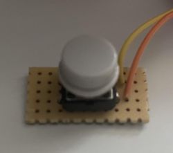
Cut a piece of verobord/stripboard to a size of 10x5 holes (see image), length should be around 28.5 to 29 mm. The connection lines on the board should run along the longer side of the board (horizontal if the board is oriented as in the image). Solder the push button to the middle of it. Then solder two wires, appr. 150 mm long so that they connect to the two button connectors on one side.
Step 3: Connect the Components

Connect the MAX7219 display to the D1 Mini (Pro):
- VCC to 5V
- GND to GND
- DIN to GPIO13 (D7)
- CS to GPIO12 (D6)
- CLK to GPIO14 (D5)
Connect the button to the D1 Mini (Pro), using pin GPIO5 (D1) and GND.
Connect the power input to the VCC and GND pins of the MAX7219 display (can also be connected directly to the D1 Mini Pro, but since the display will draw most of the power it makes more sense to connect it there and let the D1 Mini Pro be powered through the connection between the display and the D1 Mini Pro).
Please check the image in the assembly step below to see appr. how long cables you need between display and the D1 Mini (Pro), and between the switch and the D1 Mini (Pro). Around 10-15 cm should be fine.
Step 4: Configuration (software)
As a first step, you need the font "Pixelmix" uploaded to HomeAssistant, in folder /homeassistant/esphome/fonts. If the folder "fonts" does not exist, then create it (the "File Editor add-on is a helpful tool for this). The font is free for personal use, and can be downloaded here:
https://www.dafont.com/pixelmix.font
Next step is to edit the YAML file for the device, using the code below. Everything above the comment "Everything above..." should not be changed, as this part was created as part of installing the device and adding it to HomeAssistant.
Other parts you will need to adapt for your needs, here are some hints:
sensor:
This part you need to adapt, to fetch the data you need, using the sensor names of your HA system.
display lambda:
This is the actual code that will display the data. Make changes here as needed, as a minimum change the sensor names to match what you defined under the "sensor:" part.
If you leave everything else un-changed, the display will start up showing inverter (solar) power. Pushing the button will switch to showing the outside temperature, push again to go back to showing the power.
interval:
Un-comment this part if you want the display to automatically switch between values to display. If you keep it commented, you can switch between values with the button.
esphome:
  name: "solar-wattmeter"
  friendly_name: solar-wattmeter

esp8266:
  board: d1_mini_pro

# Enable logging
logger:

# Enable Home Assistant API
api:
  encryption:
    key: "********************************************"

ota:

wifi:
  ssid: !secret wifi_ssid
  password: !secret wifi_password

  # Enable fallback hotspot (captive portal) in case wifi connection fails
  ap:
    ssid: "Esphome-Web-Dae120"
    password: "************"

captive_portal:

# Everything above this line should be left un-changed, it was created during the install

# Everything below is the actual implementation

spi:
  clk_pin: D5
  mosi_pin: D7

font:
  - file: 'fonts/pixelmix.ttf'
    id: digit_font
    size: 8
  - file: 'fonts/pixelmix.ttf'
    id: digit_font_sml
    size: 6

sensor:
  - platform: homeassistant
    entity_id: sensor.inverter_active_power
    id: active_power
  - platform: homeassistant
    entity_id: sensor.netatmo_hagby_hallen_utomhus_temperature
    id: outdoor_temp

binary_sensor:
  - platform: gpio
    pin:
      number: GPIO5
      mode: INPUT_PULLUP
      inverted: True
    name: "mode switch"
    filters:
      - delayed_on: 10ms
    on_click:
    - min_length: 50ms
      max_length: 350ms
      then:
        - lambda: |-
            if (id(mode) == 1) {
              id(page) = (id(page) + 1);
              if (id(page) > 2) {
                id(page) = 1;
              }
            } else {
              id(led_brightness) = (id(led_brightness) + 1);
              if (id(led_brightness) > 15) {
                id(led_brightness) = 0;
              }
            }
    - min_length: 800ms
      max_length: 2500ms
      then:
        - lambda: |-
            if (id(mode) == 1) {
              id(mode) = 2;
            }
            else {
              id(mode) = 1;
            }

display:
  - platform: max7219digit
    id: dmx
    cs_pin: D6
    num_chips: 4
    flip_x: False
    intensity: 1
    scroll_enable: False
    lambda: |-
      if (id(mode) == 1) {
        switch (id(page)){
          case 1:
             if(id(active_power).has_state()) {
               it.printf(24,0,id(digit_font),TextAlign::TOP_RIGHT,"%.0f",id(active_power).state);
             } else {
               it.print(24, 0, id(digit_font), TextAlign::TOP_RIGHT, "----");
             }
             it.print(27, 0, id(digit_font), "W");
             break;
          case 2:
             if(id(outdoor_temp).has_state()) {
               it.printf(24,0,id(digit_font),TextAlign::TOP_RIGHT,"%.1f",id(outdoor_temp).state);
             } else {
               it.print(24, 0, id(digit_font), TextAlign::TOP_RIGHT, "-.-");
             }
             it.print(30, -1, id(digit_font_sml), TextAlign::TOP_RIGHT, "o");
             break;
        }
      } else {
        it.print(0, 0, id(digit_font), TextAlign::TOP_LEFT, "LVL");
        it.printf(30, 0, id(digit_font), TextAlign::TOP_RIGHT, "%i",id(led_brightness));
        it.intensity(id(led_brightness));
      }


globals:
- id: mode
  type: int
  initial_value: "1"
- id: page
  type: int
  initial_value: "1"
- id: led_brightness
  type: int
  initial_value: "3"

#interval:
#- interval: 2s
#  then:
#    - lambda: |-
#        id(page) = (id(page) + 1);
#        if (id(page) > 2) {
#          id(page) = 1;
#        }
Once the YAML file is updated, save it. Make sure your device is on and appears online in HA, then install the new configuration. Once installed, the display should come alive and display your data. Please note that it will display "----" for the first seconds, until a connection between HA and the device has been established.
Congratulations - your device is now ready to be mounted in the case.
If the device does not work, check the log from the ESPHome add-in in HomeAssistant, there are usually some clues there. You might also want to double-check the wiring.
Alternative code version
After using the device for some time, I decided to change the code so that it only displays the current power when the solar cells are producing electricity, and otherwise display the outdoor temperature. The button will still work, if you would like to display the temperature when the power is showing. Here's the changed part of the code for this version:
    lambda: |-
      switch (id(page)){
        case 1:
           if(id(active_power).has_state()) {
             if(id(active_power).state > 0) {
               it.printf(24,0,id(digit_font),TextAlign::TOP_RIGHT,"%.0f",id(active_power).state);
               it.print(27, 0, id(digit_font), "W");
             }
             else {
               it.printf(24,0,id(digit_font),TextAlign::TOP_RIGHT,"%.1f",id(outdoor_temp).state);
               it.print(30, -1, id(digit_font_sml), TextAlign::TOP_RIGHT, "o");
             }
           } else {
             it.print(24, 0, id(digit_font), TextAlign::TOP_RIGHT, "----");
             it.print(27, 0, id(digit_font), "W");
           }
           break;
        case 2:
           if(id(outdoor_temp).has_state()) {
             it.printf(24,0,id(digit_font),TextAlign::TOP_RIGHT,"%.1f",id(outdoor_temp).state);
           } else {
             it.print(24, 0, id(digit_font), TextAlign::TOP_RIGHT, "-.-");
           }
           it.print(30, -1, id(digit_font_sml), TextAlign::TOP_RIGHT, "o");
           break;
      }
Step 5: Printing the Case and Assembly


Printing
The STL files and the source file for the case can be downloaded here:
https://www.thingiverse.com/thing:6443928
You do not need to print the "Stand L" and "Stand R", unless you want the case to be able to stand on a flat surface.
There are two versions of the case bottom, one for the larger variant of the D1 Mini Pro (the one with a battery connector) and one for the more usual variant of the D1 Mini.
Note: When you slice the case top, make sure the first layer is less than 0.2 mm. My recommended settings are first layer 0.15 mm and remaining layers 0.20 mm. If the first layer is to thick, it will not print the "diffuser" for the display. the diffuser is just one layer thick and should cover the display completely, which makes the display nicer to look at (in my opinion).
Assembly
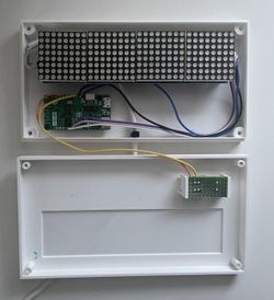
First you need to remove the two outer LED modules, then attach the display board to the case bottom with 3 mm screws (5 mm long). Re-attach the modules, and try to height-align all modules. Test fit the case top, and make sure the display modules are flush against the case top (diffuser layer). If not, then adjust the display modules height by slightly raising them in their connectors.
Attach the D1 Mini (Pro) to the case bottom, with 2 mm screws (also 5 mm long) or just slide it in place (depending on which version of the case you printed). If your version of microcontroller does not fit, you can probably attach it to only one or two of the screw holes.
Carefully insert the button assembly into the case top.
Screw bottom and top together with 3 mm screws, appr 15 mm long.
Attach the stands to the case bottom if required. When using stands, the power cable should be routed through one of the screw holes in the back instead of the hole in the bottom. If you want to wall-mount it, either hang it on two screws or just use some double-sided tape.
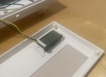
Tip for mounting the button
It can be difficult to cut the veroboard exactly so that it snap-fits into the case top. If your board is a tiny bit too short, use a zip-tie to pull the mounts together so that it grips the veroboard, as shown in this image:

Participated in the
Anything Goes Contest

![Tim's Mechanical Spider Leg [LU9685-20CU]](https://content.instructables.com/FFB/5R4I/LVKZ6G6R/FFB5R4ILVKZ6G6R.png?auto=webp&crop=1.2%3A1&frame=1&width=306)


