

Introduction: How to Solar Power Your Home Security Camera


Everyone needs security for their home, garden, and other valuables. It is never a new thing to set up a security camera for that purpose. However, it is a great idea to go for solar-powered wireless security cameras for increased and reliable security.
When we talk about the solar-powered security camera, there are two alternatives :
1. Buy a readymade solar-powered security camera system
2. Adding solar power system to the existing security camera
In this Instructable, we will cover the second alternative " DIY Solar Powered Security Camera System "
Why should you need a solar powered security camera? Because solar powered security cameras have a lot of benefits like:
1. Independence from the power grid
2. No requirement of long wires
3. Can be installed in remote sites or geographically challenging environments.
4. Minimize environmental impact
Note: This article can be used for DIY Off Grid Solar System for any load. It is is not restricted tos security camera only.
Visit my new website: www.opengreenenergy.com
Step 1: Materials Required
Step 2: Power Requirement


The first step to Solar-powered your outdoor security camera would be to identify the power requirements of your security camera.
Note down the following from the specifications :
1. Power rating in Watts
2. Voltage rating - 12V or 24V
The power rating will be required for calculating the Battery and Solar Panel size required for the Security Camera. The voltage rating is important for designing the battery bank. If your camera operates on 12 VDC you would require a 12V Battery. If your camera operates on 24 VDC you would require a 24V Battery.
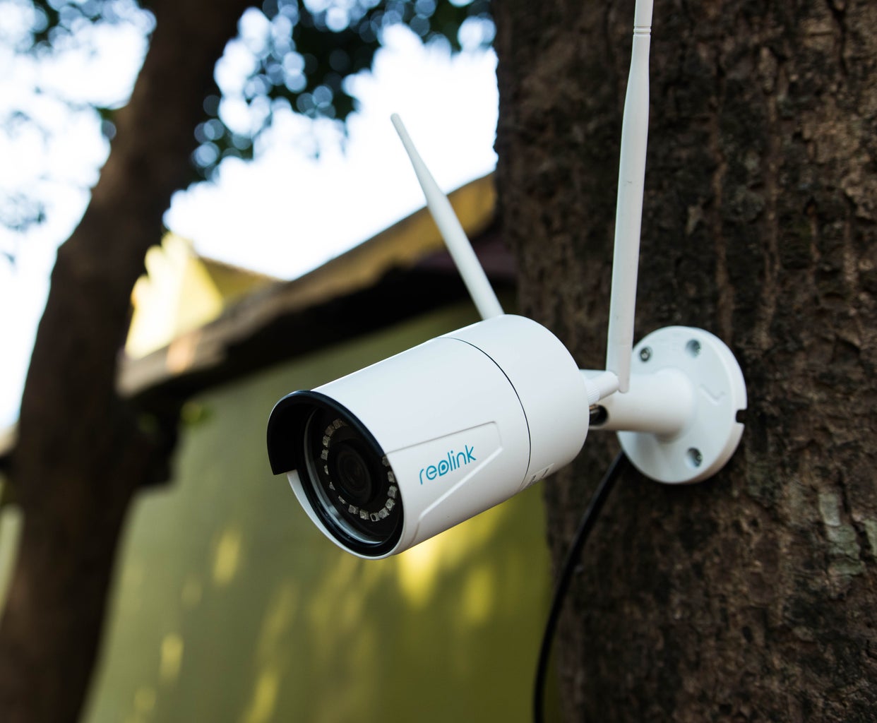
I am using the Reolink RLC-410W WiFi Camera, I noted down the power and voltage rating from the specification sheet. The specification sheet is attached above for better understanding.
Power Consumption is <8W, I enquired the actual power rating from the OEM which is 6W
The power supply voltage is 12V, so I need a 12V Battery Bank.
Step 3: Selecting the Battery


You have two good choices of battery types: Deep Cycle Lead Acid or Li-Ion
A deep cycle Lead Acid battery is less expensive and with a lifespan of 2 to 5 years and offers good performance for solar energy storage. Whereas the Li-Ion battery can be charged fast, are lightweight compared to their storage capacity. They also have a long lifespan averaging 5 to 9 years. However, these benefits come at a high cost of up to 20 times the cost of a deep cycle battery.
Sizing the Battery:
The entire power required to run the Security Camera is drawn from the Battery Pack. So make sure the solar batteries are capable of recharging fast and store enough power for continuously monitoring & recording.
Example:
The power rating of the camera = 6Watt
Watt-Hour required to run the whole day (24hrs) = 6W x 24 hrs = 144 Wh
Battery voltage = 12V
Watts ÷ Volts = Amps
Battery Capacity Required = 144 / 12= 12Ah
It is a good practice to operate the battery at 50% of its cycle. This will help to extend the lifespan of the batteries.
Multiplying the Amp-Hour by 2 ensures that you are operating on the top 50% of the Battery’s cycle, giving you 50% of its capacity remains available for future use.
So we need a Battery of 12 x 2 = 24Ah
Battery Rating: 12V / 24Ah
Note: When calculating your battery size, consider how many cloudy days you may have in a row. On cloudy days your battery will need to supply power without help from the panel.
Enclosure for Battery
The battery will need to be protected in a weatherproof container, typically called a “NEMA Box.” NEMA defines standards for various grades of electrical enclosures rated to protect against environmental conditions.
For further information on batteries, please have a look at this article.
Step 4: Selecting the Solar Panel


Once you have finalized the Battery Size, you can turn your attention to sizing the Solar Panel for your DIY solar security camera. The first step for sizing the solar panel is to identify the average peak sun hours in your area receives.
The average daily sun hours (solar insolation) in units of kWh/m2 per day is sometimes referred to as "peak sun hours" too. The term "peak sun hours" refers to the solar insolation which a particular location would receive if the sun were shining at its maximum value for a certain number of hours.
To find out the amount of solar insolation in your area, you can use the Global Solar Atlas.
For example,
As per the Global Solar Atlas, New Delhi, India receives 5.104 kWh/m2 per day (GTI)
Peak Solar Radiation = 1 kW/m2 ( Solar Panels are rated at an input rating of 1kW/m2.)
Peak Sun Hours = 5.1/1 = 5.1 Hours
To adequately charge your Battery you have to use a Solar Panel with equal or greater Voltage output.
As we have selected 12V battery system, so we have to use 12V Solar panel too. Here you should not confuse with the 12V. I wrote 12V as it is suitable for charging the 12V battery. But actually, the Solar panel voltage is around 17V or more.
Solar Panel Rating = Battery Watt-Hour / Peak Sun Hour = 288 / 5.1 = 56.47 Watt
Where Battery Watt-Hour = Battery Capacity in Ah x Battery Voltage = 24Ah x 12V = 288Wh
You will not get the rated power at the battery terminal, because of the various losses associated in the system. Taking losses into consideration, we have to add some margin in the sizing. Roughly 30% margin is Ok.
The rating of the panel shall be 56.47 x 1.3 =73.4 W
So we need a Solar panel of rating more than 73.4 W
Solar Panel Rating: 75W /12V
Alternative Way
As per the Global Solar Atlas PVOUT is 3.901 kWh/kWp per day.
This means that if we install 1 kW (1000W) solar panel, it will generate 3.901 kWh.
We have to charge the battery fully in single day sunlight,
Require Battery Capacity = 24 Ah/12V = 288 Wh
Required Solar Panel = 288 / 3.901 = 73.82 W
Solar Panel Rating: 75W /12V
image credit: https://www.titan-energy.co.uk
Step 5: Selecting the Charge Controller


If your Battery is the heart of your solar Security Camera, the Solar Charge Controller is the brain and ensures that your Battery is not over-charged or over discharged.
It is a device which is placed between a solar panel and a battery. It regulates the voltage and current coming from your solar panel. As the input voltage from the solar panel rises, the charge controller regulates the charge to the batteries preventing any overcharging.
To select the proper Charge Controller, you have to know the maximum output current of the solar panel and Battery Voltage. The maximum possible current that a PV panel can generate is the “short circuit current,” indicated as Isc in the panel’s label or specs sheet.
Now select a charge controller with,
1. Current Rating more than Short Circuit Current (Isc) with consideration of a safety factor ( 1.25 x 125 = 1.56 )
2. Voltage Rating same as the battery voltage.
Safety Factor :
1. We use a standard factor to account for all Photovoltaic (PV) output-boosting circumstances like a sunny day with very clear snowpack. (additional light reflected off the snow). That factor is 1.25 or 125%
2. A second de-rating factor may be required for systems in continuous operation, additional protection must be included, according to the National Electric Code (NEC), to allow for heat and equipment stress. This factor is also 1.25 or 125%.
So the overall safety factor is 1.25 x 1.25 = 1.56
For example,
A 75W Solar panel with Short Circuit Current (Isc) of 4.54A requires 4.54A x 1.56 = 7.08A
In this case, 7Amp or higher rated (10A) Charge Controller would be recommended.
Solar Charge Controller Rating: 10A/12V
Note: All thethree main components must match nominal voltage throughout the system: the solar panel, the solar charge controller, and the battery bank.
image credit: https://www.morningstarcorp.com/
If you like to reduce your system cost you can make a PWM charge controller. For step by step instruction, you can see my instructable on PWM CHARGE CONTROLLER.
Step 6: Selecting the Solar Cable


The current generated from the solar panels should reach the Battery with minimum loss. Each cable has its own ohmic resistance. The voltage drop due to this resistance is according to Ohm’s law
V = I x R (Here V is the voltage drop across the cable, R is the resistance and I is the current).
The resistance ( R ) of the cable depends on three parameters:
1.Cable Length: Longer the cable, more is the resistance
2. Cable Cross-section Area: Larger the area, smaller is the resistance
3. Material used: Copper or Aluminum. Copper has lesser resistance compared to Aluminium
In this application, copper cable is preferable.
You can calculate the cable size by using RENOGY online calculator.
You need to enter the following parameters :
1. Solar Panel Operating Voltage (Vmp)
2. Solar Panel Operating Current (Imp)
3. Cable Length from Solar Panel to Battery
4. Expected loss in percentage
The first two parameters ( Vmp and Imp) can be easily found from the specification sheet on the back side of the solar panel or from the datasheet. The cable length depends on your installation. The loss percentage considered for a good a design is around 2 to 3%.
In the earlier step, we have already finalized the Solar panel, the rating is 75W /12V. From the specification sheet
Vmp = 18V and Imp = 4.17A ( rounded off to next higher number i.e 5A ) .
Let the distance between the Solar panel and the Battery is 10 feet and the expected loss is 2%.
By using the above values in the online calculator by RENOGY,
The cable size is: 14 AWG
You can buy the Solar cables fromAmazonor Aliexpress
Note: The voltage grade of the cable should be matched with the Solar Panel maximum system voltage. In our case, it is 600 V.
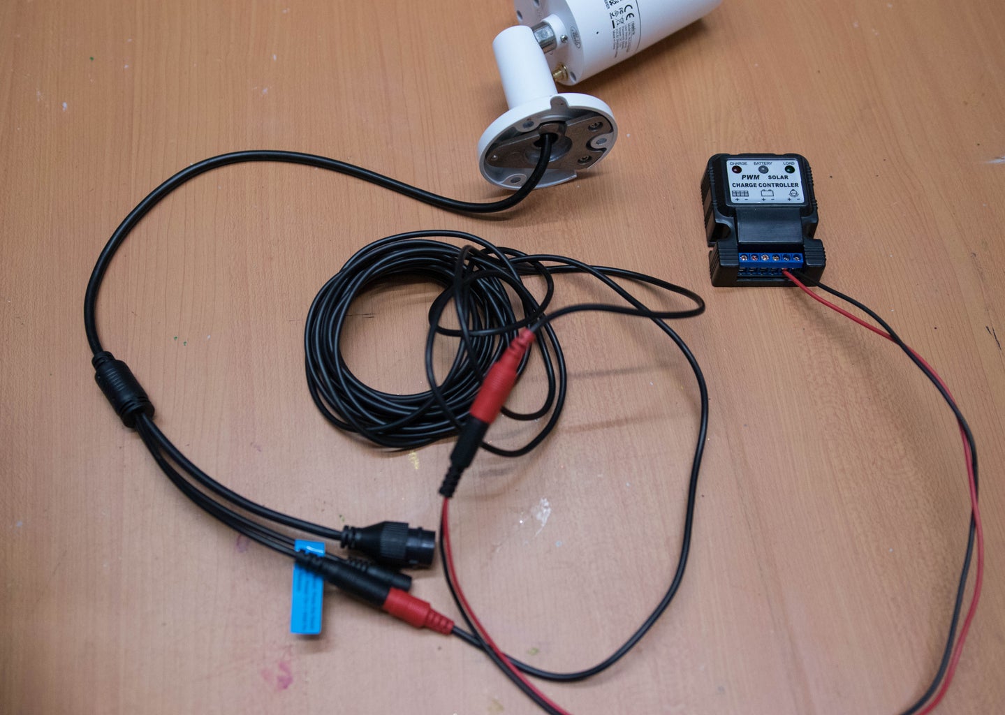
Step 7: Preparing the Power Cord
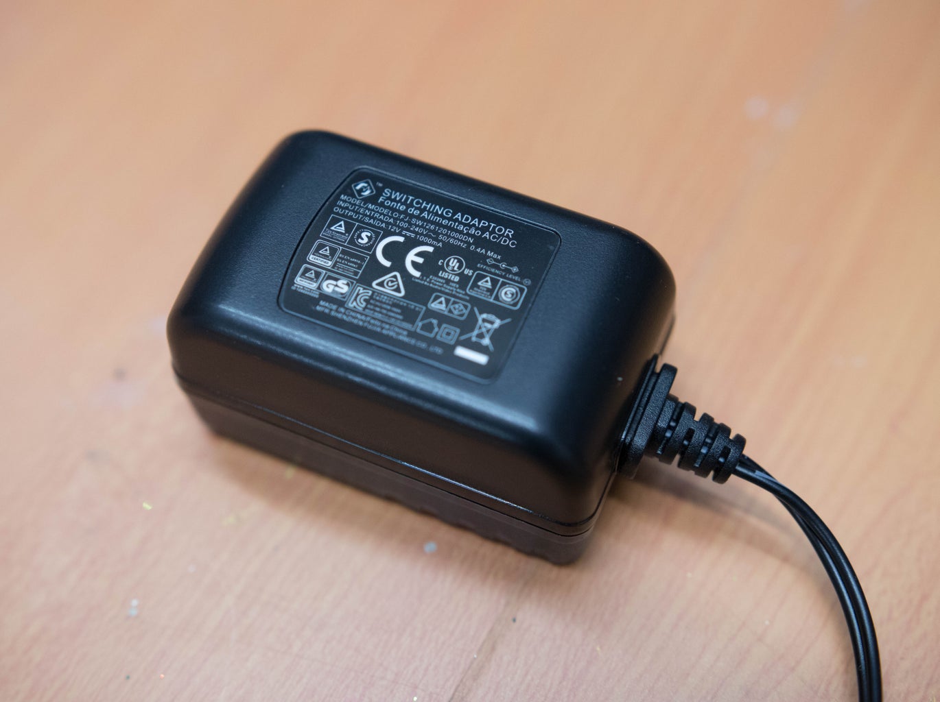


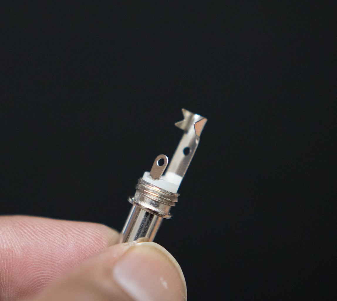


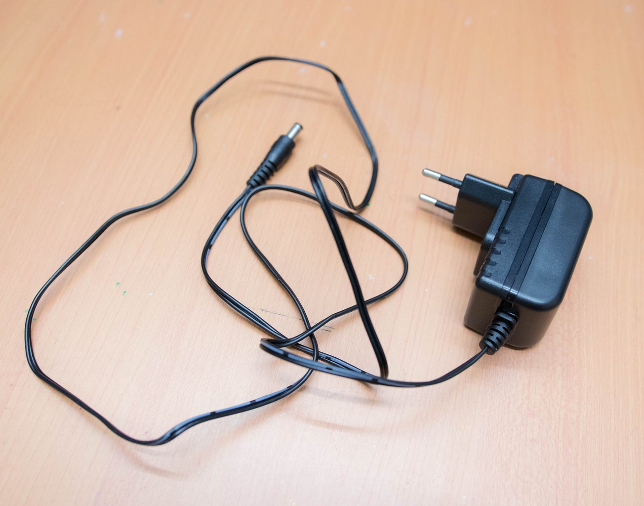
The Reolink RLC-410W camera comes with a 12V / 1A DC power supply and a long extension cable with DC Male / Female jack. Our objective is to provide power from the battery via the charge controller. So we need an additional DC mail jack for connection without cutting the original extension cable. The connection details are shown in the above picture.
Step 8: Installing the Solar Panel
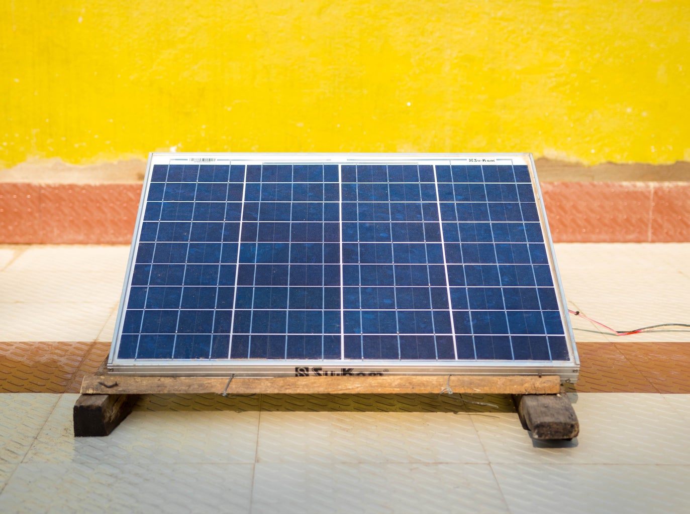
To get the maximum power from solar panels, you need to point the panel in the direction that captures the maximum sun light.It is suggested to face the solar panel to the equator where you can maximize exposure to the sunlight instead putting them in shade.
Tilt angle should be approximately equal to the latitude angle.
Step 9: Wiring


1. Connect your Battery to your solar charge controller :
Using an appropriate cross-section cable, connect your 12V battery to the battery terminals of the solar charge controller.Make sure that the positive (+) battery terminal is connected to the positive (+) terminal on the controller and do the same with the negative (-) terminals.
You can hardwire the cables onto the battery terminals, use ring terminals or for temporary connections use crocodile clips.
2. Connect your Solar panel to your solar charge controller :
Connect the positive and negative solar panel cables to the Solar Panel terminals on your solar charge controller. Again, make sure that the positive (+) cable connects to the corresponding positive (+) terminals on the controller and the same with the negative (-) terminals. If the solar panel is exposed to some light, the solar charge controller will immediately show a ‘battery charging’ signal.
3. Connect your Security Camera to your battery terminals :
Then you will need to connect your Security Camera to the Load terminals on your solar charge controller. As always, make sure that the positive (+) cable connects to the corresponding positive (+) terminals on the battery and the same with the negative (-) terminals.
You can see the above images for better understanding.
Step 10: Conclusion

After wiring all the components as per the wiring diagram, your WiFi outdoor camera is ready to operate by taking power from the sun. Now your security camera system is ready to provide the option of a reliable security system without the hassle and added expense of running cables.
Hope you have enjoyed my instructable.
If you have any suggestions for improvements, please comment below. Thanks


