

Introduction: I Made Educational Coding Board and Modules Then Programmed With ChatGPT


In this project, I will show you the assembly and use of the educational programming board and modules that I designed as open-source. I have designed four modules for now, these are LED, Buzzer, Potentiometer and Temperature Humidity sensor. In addition, the mainboard enables dual DC motor and one servo motor control. Also, all the source codes in the project was created by the very popular ChatGPT recently, with amazing results. Let's take a look at how it works!
Step 1: How It Works?
The mainboard is based on ESP8266 WiFi and has four standard RJ25 ports. Ports such as RJ25 are also often preferred on other popular programming boards. This allows the modules to be easily connected to the mainboard and used. It can be programmed just like an ESP8266 WiFi microcontroller boards. In addition to one servo motor control, it enables dual DC motor control with the DRV8848 motor driver on it.
Step 2: Printed Circuit Boards


Printed circuit boards are preferred for long-term use, stable and more durable electronic circuit prototypes. I prefer PCBWay to turn my circuit designs into durable prototypes. If you want to have these PCBs with low-price and high-quality, you can visit the shared links.
- PCB file for the mainboard - https://www.pcbway.com/project/shareproject/I_made_an_open_source_educational_programming_board
- PCB file for the modules - https://www.pcbway.com/project/shareproject/Modules_for_Educational_Programming_Board
Step 3: Using Solder Stencil


Some "surface mount device" ie SMD components are preferred in PCBs, this affects the size and cost of the board design. For the assembly of SMD components, a stencil is generally preferred.
I needed a stencil for the mainboard, there are more SMD components on the mainboard. The components used for the modules can be easily soldered with a soldering iron.
Solder stencils help to accurately apply solder paste in position of components and the stencil is usually ordered with the PCB. This process is simple, first fix the printed circuit board and place the stencil to match the board. Then put some solder paste on the stencil with the help of a spoon and spread it with a spatula.
Step 4: Placing the Necessary Components for the Mainboard


After applying the solder paste, it is necessary to place the required components on the PCB. Where to place these components is usually indicated by a designator or footprint reference. These references are used as part of the PCB design and ensure the correct placement of components. Designator shows what a component is and where it is located. For example, a resistor's designator starts with a number such as "R1", "R2", which indicates the resistor's position on the PCB. A footprint specifies the physical dimensions of a component and the locations of its ports.
The list of SMD components required for the mainboard is as follows:
- 11x 100nf 0805 Capacitor
- 5x 100uf 1210 Capacitor
- 1x 10uf 0805 Capacitor
- 1x 2.2uf 0805 Capacitor
- 1x 1N4001 SOD-323 Diode
- 2x LED Green 0805
- 2x LED Blue 0805
- 2x LED Red 0805
- 1x LED Yellow 0805
- 1x AON7401 Mosfet
- 2x Mini SMD Tact Switch Buton 4 Pin
- 1x LM1117 5V Regulator
- 1x LM1117 3V3 Regulator
- 1x DRV8833 or DRV8848 Motor Driver
- 1x AI-Thinker ESP-12F ESP8266MOD
- 1x CH340E USB to Serial IC
- 1x Type-C USB4105-GF-A
- 2x 5.1K 0805 Resistor
- 3x 1K 0805 Resistor
- 4x 22R 0805 Resistor
- 2x 0R 0805 Resistor
- 8x 10K 0805 Resistor
- 2x 200mR 1206 Resistor
Attachments

Step 5: Soldering the Mainboard


After the components are placed on the solder pads with the help of solder paste, the soldering process begins. Soldering is usually done with a hot plate machine or a hand soldering iron.
The soldering machine heats and melts the solder paste and fixes the components in place. After the soldering is complete, the components are completely fixed in place when the solder paste has cooled.
After soldering a few more components, the board will be complete. These components are a few headers and RJ25 jacks. It can be easily soldered with a soldering iron.
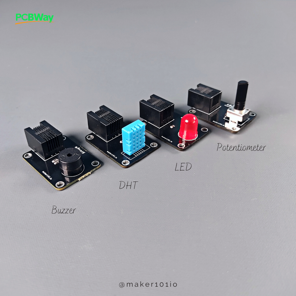
Step 6: Necessary Components and Soldering for Modules


In this step there is the soldering process of the modules. The modules are a potentiometer, a humidity and temperature sensor, a buzzer and an LED. It is possible to solder the modules with a soldering iron. For DHT sensor, you can choose version 11 or 22. You can see the locations of the components used in the modules in the shared designator.
By the way, I mixed up the LED and Buzzer module names, but the corrected and updated file has been shared with you. If you have any module add-on suggestions, please share them in the comments.
- 1x 330R 0805 Resistor
- 1x 1K 0805 Resistor
- 1x 100R 0805 Reistor
- 1x 4K7 0805 Resistor
- 1x BC817 SMD Transistor
- 4x RJ25 6pin Jack Connector
- 1x 12mm Buzzer
- 1x 10mm LED
- 1x Potentiometer
- 1x DHT11 / 22
Step 7: Programming With ChatGPT (LED and Buzzer Blink)


In this part, grab a cup of coffee and take a closer look at what we can do with ChatGPT! ChatGPT is a popular AI tool, many of you probably know or are using. In the first step I asked ChatGPT to generate a simple Blink code for the LED and Buzzer. Of course, I specified the pins to which the modules will be connected.
The result is quite successful, I copied the generated code and pasted it in the editor. By the way, if you do not have ESP8266 WiFi setup, you will have to complete it by reading the previous project.
There is a simple thing to do while uploading the code, when you see the "Connecting..." notification, press the boot and reset buttons at the same time, then release the reset and then the boot button. The upload will be completed in a few seconds.
Let's plug the modules into the pins specified in the code and see the result... As you can see in video, both the mainboard, the modules and the code are working properly.
Attachments
Step 8: Servo Motor Control With Potentiometer


Now let's test the pot module and the servo motor. What I want from ChatGPT is to generate a code for servo motor control with a pot connected to its analog pin. The result is amazing, added the servo library and used the map function.
Also added the WiFi settings. Since we will not be communicating over WiFi in this project, we are making the settings passive. Then we upload the code to the board. The result is successful again, the pot module and the servo are working successfully...
Attachments
Step 9: DHT Humidity and Temperature Sensor


The next module is a humidity and temperature sensor. I specified the pin that the module is connected to the board and also the library called DHT to use. I wanted it to generate a code that could display sensor values via serial monitor.
As you can see, the result is again great! Let's upload the generated code to the board and see the values on the serial monitor. The humidity and temperature module also performs its function successfully.
Attachments
Step 10: DC Motor Control With PWM


In the final step, let's try to generate code for a DC motor control. The 8848 driver is used for controls the DC motors, so I mentioned this in the question. Next, I defined the pins for the forward and backward motor movements. The driver contains sleep mode and I have specified the pin it is connected to.
Actually the result is fine, but it may have messed up the sleep mode a bit. Perhaps I should add a little more detail to the question. I wrote the details of the sleep mode, and also asked it to use "Pulse Width Modulation" for the motor movements. This result is really great for DC motor control with pulse width modulation! It will only require a minor change over sleep mode.
Only defining the sleep mode pin as high in the "Setup" section will be sufficient for motor movement. I delete the sleep mode lines defined in the motor movement functions and then the code is ready. Motor speed values can be defined optionally because "Pulse Width Modulation" is used.
There is the 1117 5Volt regulator on the motherboard, which makes it possible to supply it with an external power source. The motor movement LED indicators on the motherboard are working correctly, so the motor is running successfully. Thanks for reading! Please like and share for support...


![Tim's Mechanical Spider Leg [LU9685-20CU]](https://content.instructables.com/FFB/5R4I/LVKZ6G6R/FFB5R4ILVKZ6G6R.png?auto=webp&crop=1.2%3A1&frame=1&width=306)


