

Introduction: Integrated Circuits


Through the use of integrated circuit chips, creating things with electronics really starts to get interesting. Integrated circuits add worlds of functionality to your project. To be able to easily reproduce the function of some of these chips would require complex circuits with hundreds of components. By cramming complicated processes into these little unassuming computer chips, electronics manufacturers opened up the gates to the world of modern computing. While they might seem like mysterious black boxes, they don't need to be. Let's learn how to decipher and use these chips.
Step 1: What Is an Integrated Circuit?

Consider the simplest stereo audio mixer we made earlier that consisted of just four resistors. Imagine the whole thing was placed inside of a black project box, and there were input and output terminals that let us access parts of the circuit.

Now, imagine we wanted to add potentiometers to adjust the volume to each input. We would just attach the potentiometers to the appropriate terminals on the box. Integrated circuits typically require external components to be attached in order to take full advantage of their functionality.

Now imagine this whole box was squeezed into a tiny computer chip. That is basically all an integrated circuit is.

Each pin on an integrated circuit represents an input or output to or from a specialized circuit that is build into the chip itself.

In a schematic, an integrated circuit looks like a box with lines protruding from it. The box is typically labeled with the name of the chip. The pins will usually be labeled with their number. If not, assume the one in the left is pin 1, and read it like you would any other integrated circuit (which will be covered shortly).
Step 2: Types of Integrated Circuits

Just as there are endless circuits you can build using electronics, there are endless amounts of integrated circuit chips out in the world. There are so many, it is impossible for me to tell you about them all. Even talking about logic gates, which are amongst the most common integrated circuits, can be an entire class unto itself. And then, even if you did an entire class on logic gates class, you would still be scarcely scratching the surface of what integrated circuit chips can do.
The world of integrated circuits is vast, and there is a lot to learn. Fortunately, you do not need to know everything. Once you learn the basics of deciphering their functionality, it is simply a matter of research, exploration, and experimentation.
Step 3: Datasheets

Nearly any electronic component you encounter has a datasheet associated with it.
Datasheets tend to tell you helpful things like the maximum and minimum voltage a part can take, its absolute current rating, its physical dimensions, and a wide array of other helpful data.
When working with an integrated circuit chip, you absolutely need its datasheet. The reason for this is because it tells you what each of the pins does. Without this, you would be lost.
As you can see from the first two pages of the 555 datasheet shown here, there is an internal diagram and pin-out information. If you were to find and download the full datasheet for the 555, you will also find electrical ratings, application notes, and example circuits.
To find a chip's datasheet, you can either search Google, or find the part on the website of a large electronics distributor such as Digikey or Mouser. They will have current datasheets for every part in their inventory.
Step 4: 'Reading' an Integrated Circuit

This is another component that has its name printed directly on it. Sometimes it also has additional information printed on such as manufacturing codes. The chip above is a CD4017 decade counter. All of the additional information printed on there is largely irrelevant.
When getting started, you might find yourself looking up the wrong numbers. As you get the hang of it, you will begin to understand which ones are meaningful and which are not.
Once you know what the chip is, the next thing to do is determine which end is up by finding the chip's 'top' marking. This marking is typically a little U-shaped notched into the top of the chip. On smaller chips it can also be a small round indent near one of the corner pins.

Once you find the marking, rotate the chip so that the marking is pointed either upward or away from you.

Now, if you were to look at the furthest pin on the top left, that is pin 1. The pin numbers increase sequentially down the left side until you reach the end.

Once you reach the last pin on the left side, begin again on the right side with the pin closest to you. This is whatever number is next in the sequence from where you left off. Then, to determine the remaining pin numbers, you can then count sequentially away from you on the right side.

Basically, you read the pins in a big counterclockwise U-shape like the notch at the top (likely coincidental).
Step 5: Deciphering

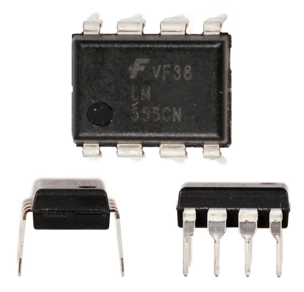
Let's take a moment and look at a 555 chip. This chip was first produced back in 1971. Nearly 50 years later it is still widely popular, and with over a billion manufactured yearly it is one of the most common chips you may encounter.

The chip is basically a timer chip. This doesn't mean it tells time, but does something at a programmable interval. In other words, this can be used to create a pulse generator and produce square waves by turning the output on and off rapidly.
The square wave is a digital waveform because it is either entirely on or entirely off. The 555 chip serves as a transition between the now familiar world of analog electronics to the strange new world of digital computing. For this reason, it is perhaps a fitting component to end the class with.
Once you identify the top of the 555 chip and can read the pin numbers, you can cross reference them with the datasheet to figure out what the pins actually are. There will often be a chart on the datasheet which looks something like this. Note that some of the pins are abbreviated. Until you get familiar with electronics, you may need to play detective on the datasheet to figure out what these abbreviations mean. Feel free to examine an actual 555 datasheet.

Let's take a trip around the chip for a moment and discuss what each pin is.
Pin 1 - This is the ground pin. You connect it to ground. Most integrated circuits typically have a ground pin.
Pin 2 - The trigger pin is the input. When this pin gets connected to ground, it triggers the output to turn on at the supply voltage.
Pin 3 - The output is where the result of the chips inner workings is output. The pin is either entirely on at the supply voltage (high) or entirely off at ground (low).
Pin 4 - As the name implies, the reset pin resets the chip when connected to ground. It is not used often and in many circuits connected to power to prevent accidental resetting.
Pin 5 - The control pin allows the chip to be controlled by external voltages. This is typically electric waveforms created by other integrated circuit chips and is not commonly used.
Pin 6 - The threshold pin looks for changes in voltage from an external timing capacitor and both grounds the output pin and resets pin 7 when a voltage crosses a threshold of 2/3 the supply voltage.
Pin 7 - This pin discharges an external timing capacitor to ground when triggered. This pin is crucial in determining the timing on the output pin.
Pin 8 - VCC is simply another way of saying power. This pin is simply connected to the power supply and used to power the board.
While this may seem intimidating right now, all of this will be explained further later. I just wanted to illustrate that even though it may look like a black box, each pin serves a purpose in the greater whole. It's just a matter of looking at the datasheet and researching the internet to understand what each pin does.

The pin functionality is not happening arbitrarily or by magic. As mentioned earlier, there is actually a circuit that has been miniaturized and jammed onto the chip. You can see here how the circuit relates to the different pins. When you look closely, you will see it is just a bunch of transistors, resistors and diodes.
If you were particularly enterprising, you could use the knowledge you have just acquired and build this circuit. However, it would be a gigantic mess of wires and take a long time. Besides, there is really no need. Thanks to this tiny integrated circuit chip, you can incorporate this whole circuit into your project with one simple part.
Step 6: Breadboarding

If you wondered why breadboards are laid out in the manner they are, it is to allow for integrated circuits to straddle the center. You can insert a chip in the middle, and each pin will have its own bus line that you can connect additional components to. This makes it easy to experiment with connecting different components to integrated circuit chips.
If you want to try working with, check out my Atari Punk Console Synthesizer instructable.


