

Introduction: Make Your Doorbell Smart With an ESP8266


Hello and welcome to this guide! Today let's see how we can turn an ordinary front door bell into a smart doorbell, so a doorbell that's connected to our smart home ans so to our smartphone. This idea came from a problem: in my house the doorbell chime is in the electrical panel with the main switch. The electrical panel has its own door, and it is itself inside a cabinet. So if someone rings the doorbell it can be heard very little, and my idea was to get a notification on the phone when someone rings. This system is very useful for me also because I often build my projects in my garage, so with the notification on my phone I know if someone rings the doorbell while I'm in the garage. But now, let's get started!
To see all the details about this project, watch the video on my YouTube channel (it is in Italianbut it has English subtitles).
Supplies
For this project we will need just two main components:
- An ESP8266 Wemos D1 board (or another ESP board)
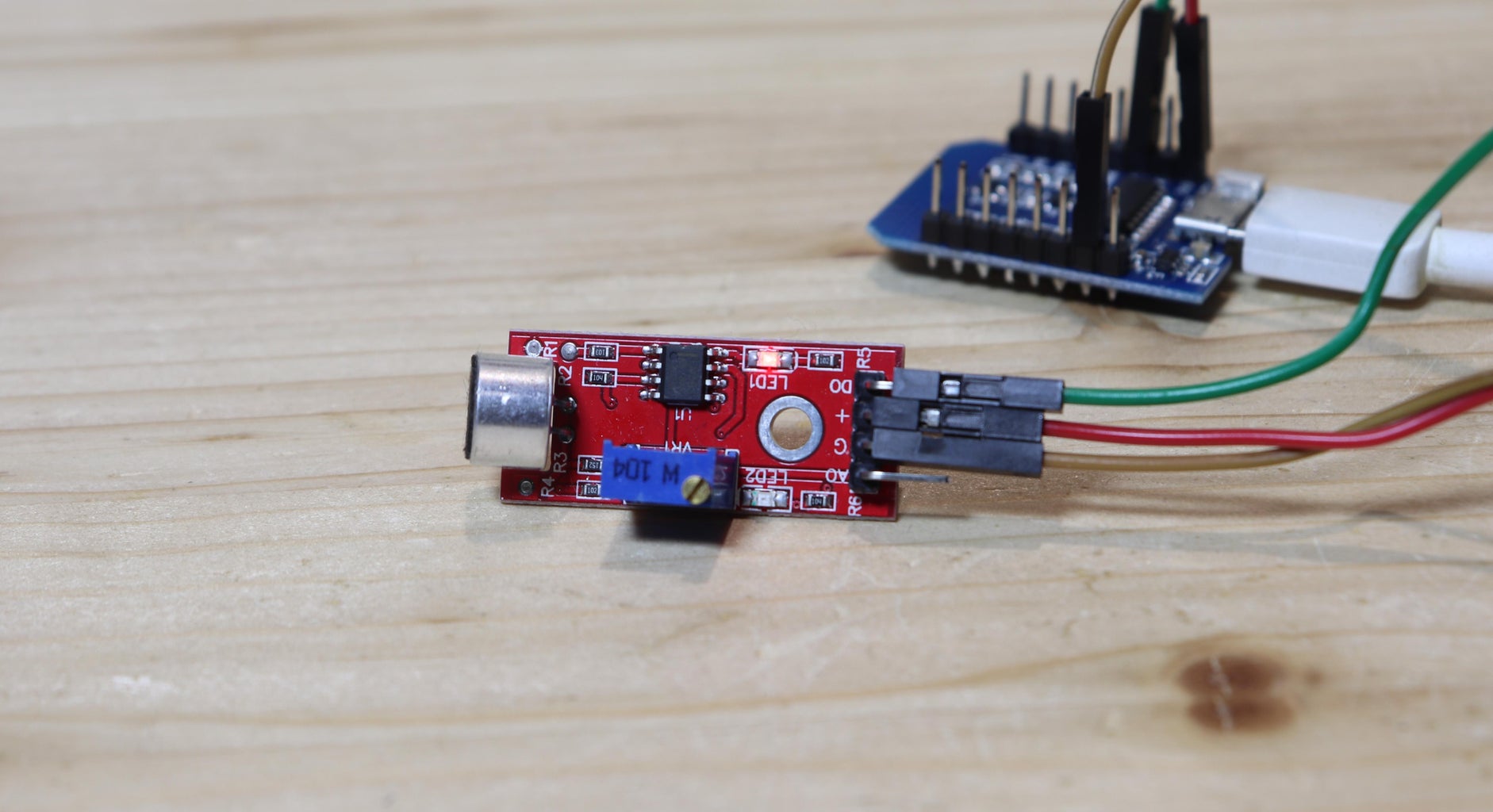
- A microphone module for Arduino (shown in the picture)
To make the circuit more neat I used:
- A piece of perfboard
- A JST connector
Tools:
- Soldering iron
- 3D printer with filament (optional)
Step 1: Project Overview

The system we will see today to connect the doorbell to home automation is based on an ESP8266 board. This board is a kind of Arduino, but with a much more powerful chip and connection to WiFi. In order for the ESP8266 to hear when someone rings the doorbell, I used this board with a microphone on it made especially for Arduino. Surely there are other ways to detect when the doorbell is rung, but using the microphone has the great advantage that we do not have to make any changes to the electrical system. In fact, we only need to place the board with the microphone near the doorbell chime. This board with the microphone has the microphone at the top here and the connection pins below, with positive, ground, digital output, and analog output. The digital output is activated when the noise detected by the microphone exceeds a certain threshold. To adjust this threshold you have to turn the small potentiometer that is on the pcb. The board with the microphone will be connected later to the ESP8266.
Step 2: Home Assistant and Software

To connect the ESP8266 to our smart home and to our mobile phone we will use Home Assistant and ESPhome. Home Assistant is a system that works locally and allows us to connect all our home automation devices together, such as light bulbs to smart outlets.
To run Home Assistant I use and old Windows PC running a virtual machine, but if you have it you can use a Raspberry pi, which consumes less power. To see the data from your smartphone you can download the Home Assistant app. To connect from outside the local network I'm using the Nabu Casa Cloud, which is the simplest solution but it's not free. There are other solutions but they are not totally safe.
ESPhome is an add-on to Home Assistant that allows us to connect ESP cards to Home Assistant via WiFi. To connect the ESP8266 board to ESPhome you can follow these steps:
- Install the ESPhome plugin in Home Assistant
- On ESPhome's dashboard, click on New device and on Continue
- Give your device a name
- Select ESP8266 or the board you used
- Copy the encryption key that is given, we will need it later
- Click on EDIT to see the device's code
- Under the name of the board you've chosen, write the type of board; if you used the same board as me, it will be:
esp8266:
  board: d1_mini
- Under wifi, insert your wifi ssid and password
- To make the connection more stable, you can give the board a static IP address, with this code:
wifi:
  ssid: yourssid
  password: yourwifipassword


  manual_ip:
    # Set this to the IP of the ESP
    static_ip: 192.168.1.61
    # Set this to the IP address of the router. Often ends with .1
    gateway: 192.168.1.1
    # The subnet of the network. 255.255.255.0 works for most home networks.
    subnet: 255.255.255.0
- At the end of the code, paste this:
binary_sensor:
  - platform: gpio
    pin: GPIO13
    name: "Campanello porta"
    device_class: sound
    filters:
      - delayed_off: 2000ms
    on_press:
      then:
        - light.turn_on: led
        - delay: 4s
        - light.turn_off: led

light:
  - platform: status_led
    name: "Led stato campanello porta"
    id: "led"
    pin:
      number: GPIO2
      inverted: true
If you are using the same board as me, probably the pins used in the code will be ok for you, but if you are using another board, you will probably need to change the pins.
- After the code is complete, we can click on Install, connect the ESP8266 to our computer and follow the instructions on screen to upload the code (it's very easy!)
- When the ESP8266 is connected to the WiFi, we can go to the Home Assistant settings, where we will probably see that Home Assistant has discovered the new device
- Click on configure and paste there the encryption key
If you do not have Home Assistant to connect the ESP8266 to the Internet, you can use the Blynk platform, that is partially free and doesn't require a computer to run. However, this code doesn't work for Blynk.
Step 3: Connections

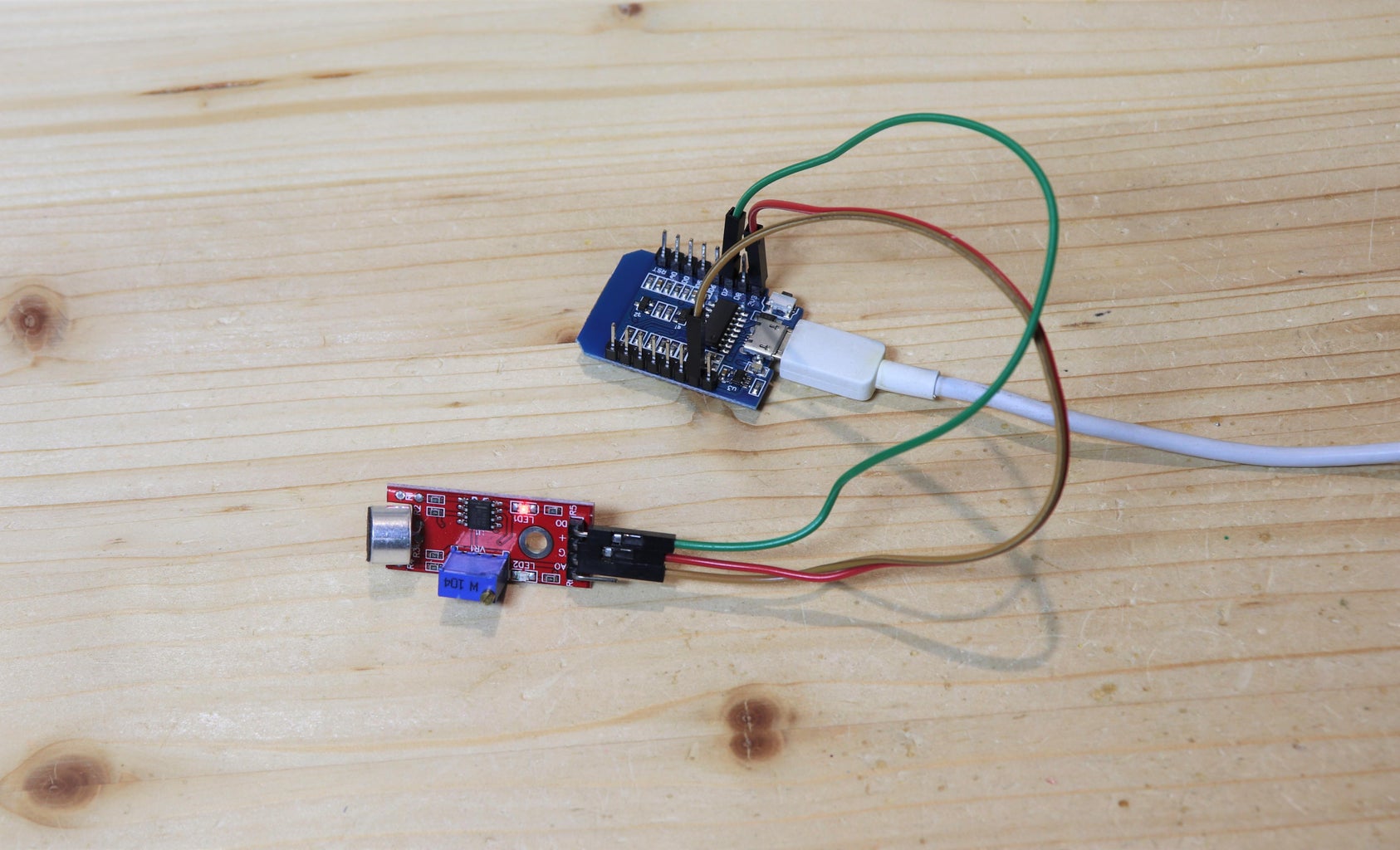
Now that we have programmed the ESP8266 we can connect the board with the microphone. I connected ground and 3.3v of the ESP8266 to ground and 3.3v of the microphone, and pin D7 of the ESP8266 to the digital output of the microphone, following the schematic on top.
Now if we touch the microphone, and this will be picked up by the microphone as a noise, we see on Home Assistant's entity that it has detected a sound.
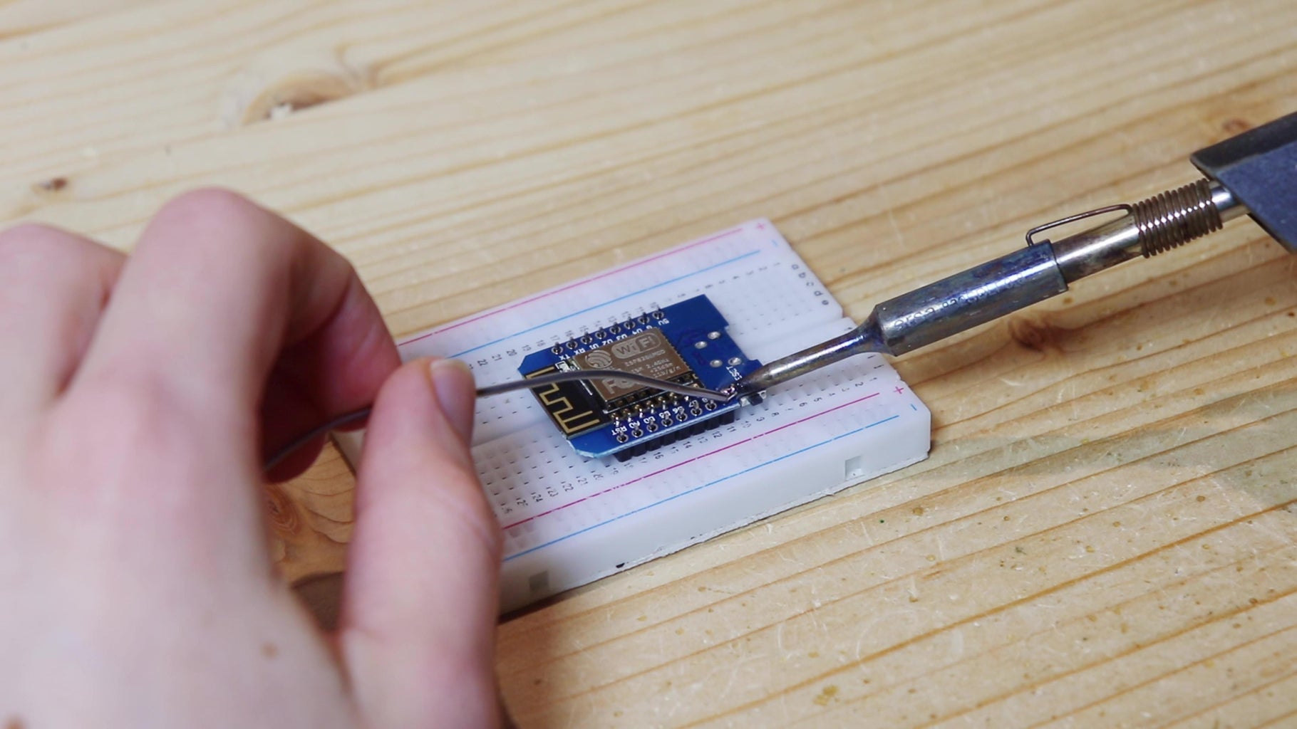
Step 4: Enclosure
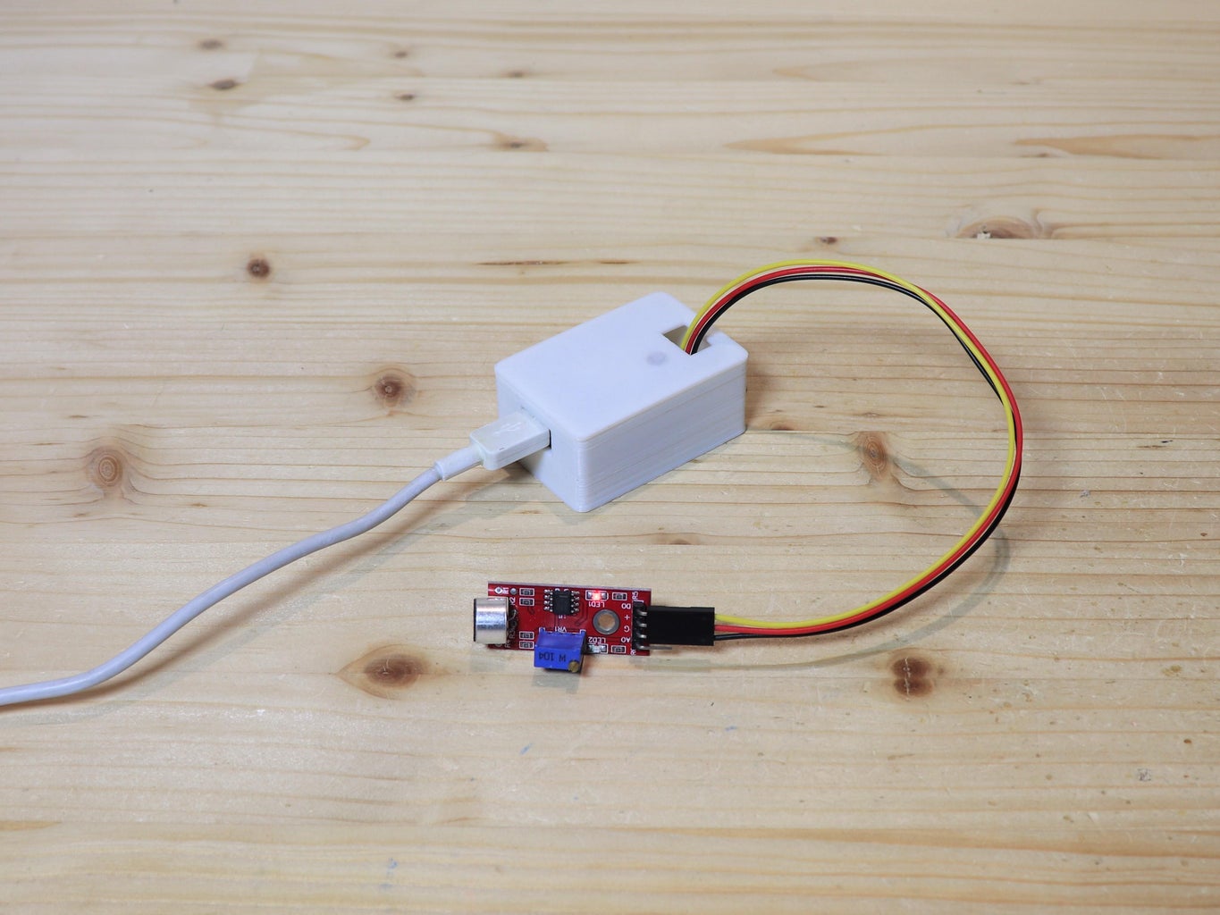
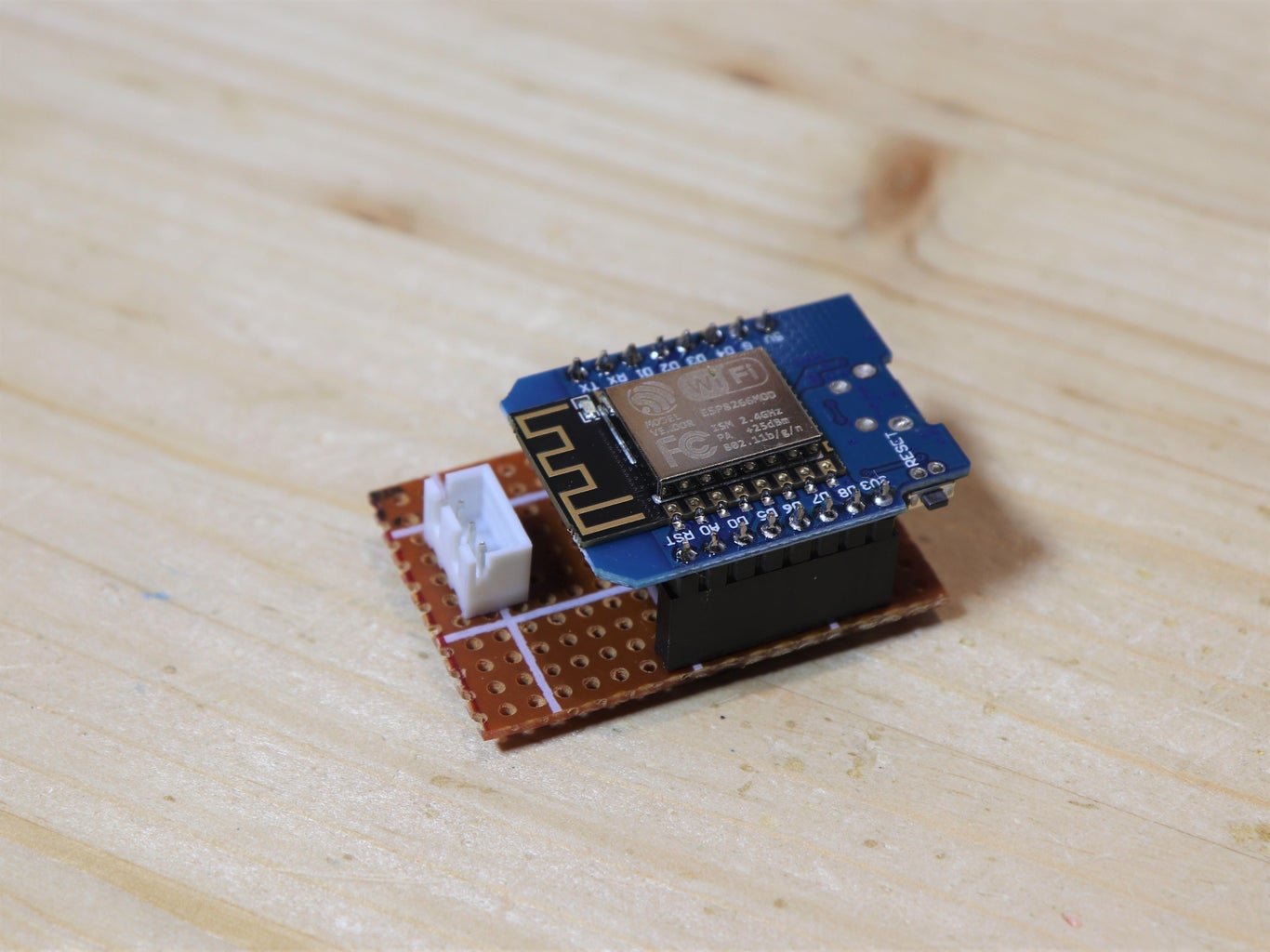


Now we just need to turn this test circuit into something that looks more like a finished product. I will mount the ESP8266 on a perfboard. First I cut a piece of perfboard. Then I soldered jumper connectors to the perfboard to mount the ESP8266. I also soldered a JST connector, to which I connected the board with the microphone. I made the same connections underneath the perfboard as we saw before, this time by soldering some wires. To connect the microphone, I found this cable that has a jumper connector on one end and a JST on the other. Then I 3D printed a small box in which to put the ESP8266. On the lid of the box I made a hole which has just 1 layer of 3D printing that matches the position of the ESP8266's onboard led, to see the led trough the white PLA also when the box is closed. I closed the box with the lid and let the microphone wire pass trough the hole on the lid. Below you can find the STL files for 3D printing.
Smart doorbell enclosure

Step 5: Installation


Now that we have finished the construction, we can mount the microphone next to the doorbell chime to send the notification when it is being rung. The doorbell chime is in this electrical panel, so I attached the small box with the ESP8266 next to the box with double-sided tape. Then I attached the pcb with the microphone next to the chime with another piece of double-sided tape. To power the ESP8266 I used a USB power supply.
Now I adjusted the microphone sensitivity potentiometer so that it comes on when the doorbell is rung, but it doesn't come on with other noises.
Step 6: Home Assistant Automation


To receive a notification on my phone when someone rings the doorbell, which is the purpose of this project, I created a very simple Home Assistant automation, which you can see in the screenshot above. Here's how it works:
- To be activated, the automation checks whether the microphone on the doorbell has "heared" the chime
- In the actions, the automation uses the notify service of Home Assistant to send a mobile notification
Step 7: Finished!


So, here's our finished project. For me, it works great and I always get the notification when someone rings the doorbell. The only problem I noticed is that sometimes the microphone picks up other noises, so I had to carefully adjust the sensitivity potentiometer on the microphone board to get notifications only for the doorbell sound.
I hope you found this guide interesting and maybe useful. To see come of my other projects, check my YouTube channel.
To see all the details about this project, watch the video on my YouTube channel (it is in Italianbut it has English subtitles).


![Tim's Mechanical Spider Leg [LU9685-20CU]](https://content.instructables.com/FFB/5R4I/LVKZ6G6R/FFB5R4ILVKZ6G6R.png?auto=webp&crop=1.2%3A1&frame=1&width=306)


