

Introduction: Make a Headphone Amp V2


After discovering Cew27'sCmoy Headphone Amp a few months ago on Instructables, I've been inspired to build my own.
I was also inspired by Koogars amazing Crystal CMoy Free Form Headphone Amplifier which I have been admiring for a few years now. I even did a bunch of projects using resin because of this project!
This is my second headphone amp build – my first can be found here. What I really like about this one compared to the first build is a couple of things. Firstly, it’s a simpler build and only needs one IC to run it, and second, you don’t have to worry about separating the input and output grounds as I did with the first build.
Also, in my opinion it has better sound quality then the first build and seems more stable. There is still a small amount of interference sometimes if your mobile isn’t switched to air plane mode, but I don’t think this is really avoidable. Once your phone is on air plane mode, there is no detectable interference and the amp works perfectly.
You might be asking yourself right about now, what the hell is a headphone amp and why do I need one! Your phone doesn’t really have the power to drive a pair of headphones. You can hear this when you listen to music through your phone speakers, the sound sounds flat and has no real range. When you plug your headphones into a separate amp, you’ll be astonished at the level of audible improvement in clarity, detail and dynamics you get out of your speakers.
So without further ado – let’s get cracking
Step 1: About the Amp Circuit I Choose to Build

The amp is built using op amp 5532. The op amp is a low-distortion, low-noise device, which can drive low-impedance loads to a full voltage swing while maintaining low distortion. Furthermore, it is fully output short-circuit proof. I’ve included the datasheet on the op amp in case anyone is interested.
The other positives about this op amp is it’s cheap, you only need 1 for the circuit and you don’t have to worry about virtual grounds or trying to separate the input and output grounds.
Also, when you first look at the schematic it might seem that there are 2 op amp IC’s. There is actually only one and is done this way so it is easier to design.
The end result is a high quality, high performance portable device that is relatively easy to build and will change the way you listen to music from your phone.
Attachments


Step 2: Tools and Parts


Parts:
It might seem like you need a lot of parts buts most can be purchased in bulk and if you already mess about with electronics then you will probably have most of the components already.
1. 10K duel gang Potentiometer – eBay
2. Potentiometer knob - eBay
3. 2 X 18K Resistor – metal film – eBay
4. 4 X 68K resistor – metal film – eBay
5. 47K resistor - eBay
6. 5mm LED – eBay
7. NE5532 IC – eBay (10 IC's for just over a dollar!)
8. 8 pin socket holder - eBay
9. SPDT switch - eBay
10. 3 X 4.7uf capacitor – eBay
11. 2 X 22pf ceramic capacitor – eBay
12. 3 X 220uf capacitor – eBay
13. 2 X 3.5mm stereo jack socket – eBay
14. Prototype board - eBay
15. 9v battery holder - eBay
16. 9v battery
17. Wires
18. Case. I used a small tin case - check out eBay if you want to use one similar. You could use a tobacco tin or an altoids tin or something similar - eBay
19. You’ll also need a male to male 3.5mm cord - eBay
Tools
1. Drill
2. Soldering iron
3. Pliers
4. Wire cutters
5. The usual, basic tools that you have in your tool box
Step 3: Making the Circuit - Part 1


First thing to do is to take a good look at the circuit design and breadboard it to make sure it works for you.
NOTE – Although it might look like there are 2 IC's in the schematic, it's actually only one which has been split. This allows for a clearer schematic
Steps:
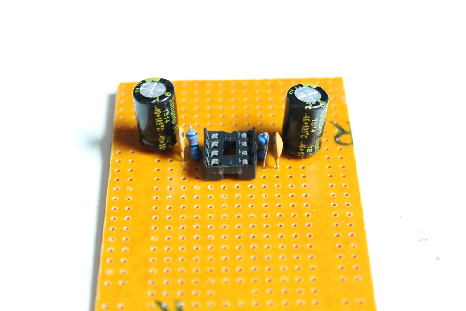
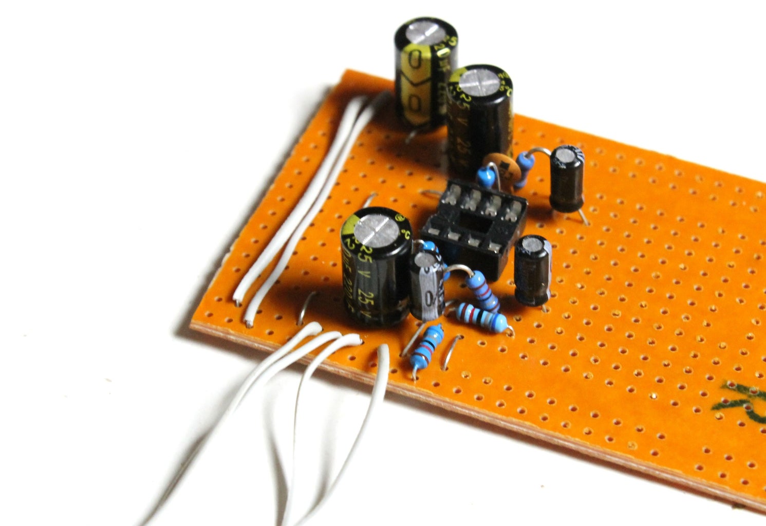
1. Solder the 8 pin socket into the prototype board. Make sure you give yourself enough room on either side if the socket, you can always trim the prototype board later once you have finished the circuit
2. Solder one of the 68K resistors to pins 1 and 2 and also another to pins 6 and 7
3. Solder a 22pf cap to exactly the same pins
Step 4: Making the Circuit - Part 2
As you are building the circuit, you’ll start to run out of
room quickly on pins 2 and 3 on the IC. Just make sure that you try and make room for all of the components.
Steps:
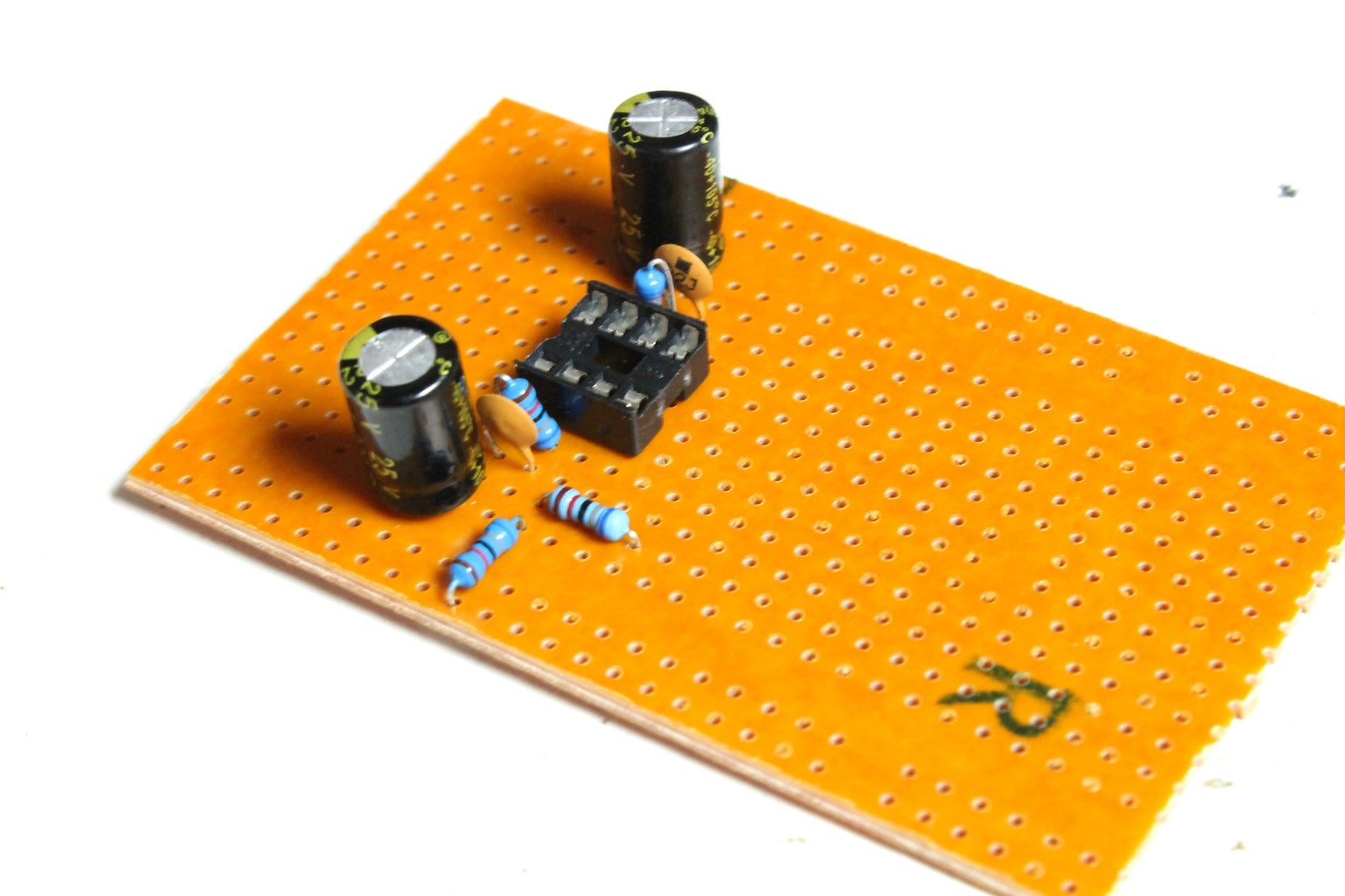
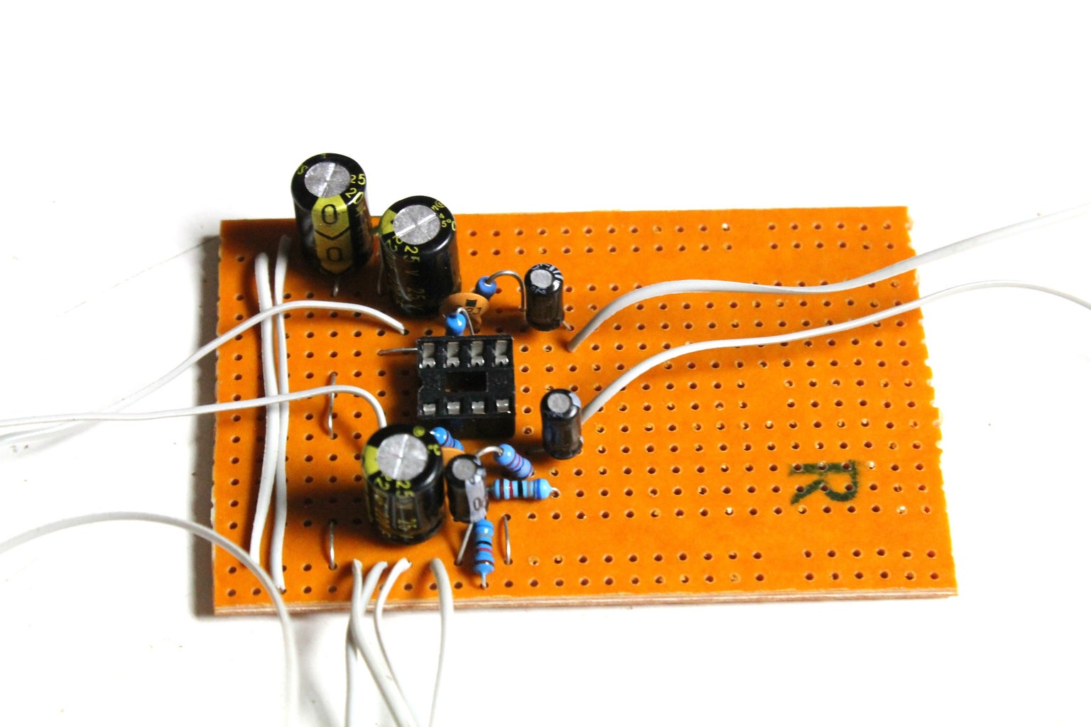
1. Next, you need to add the 220uf capacitors for the output socket.
2. Solder the positive leg on the cap to pin 1 on the IC. Solder the ground leg to a solder point on the prototype board that is open
3. Solder the positive leg on another 220uf cap to pin 7 on the IC. Again, solder the ground leg to a solder point that is open
4. Pin 3 needs to have 3 components attached to it. 2 68K resistors need to be connected to pin 3. One then needs to be connected to ground and the other positive.
5. Next, you need to add a 4.7uf cap. Solder the positive leg to pin 3 and the ground leg to ground on the prototype board
See I told you it starts to get a little squashy on the board
Step 5: Making the Circuit - Part 3


Steps:
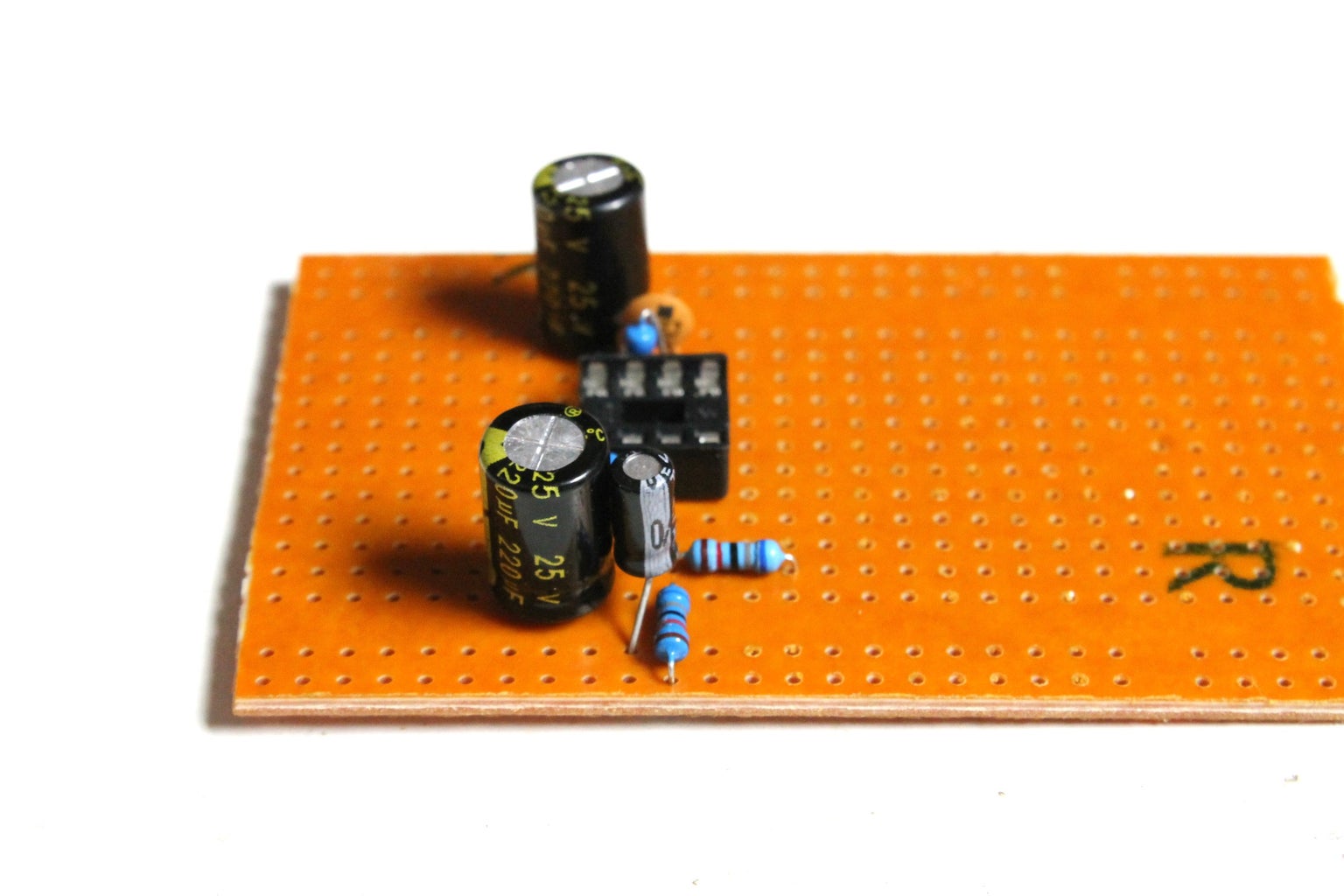
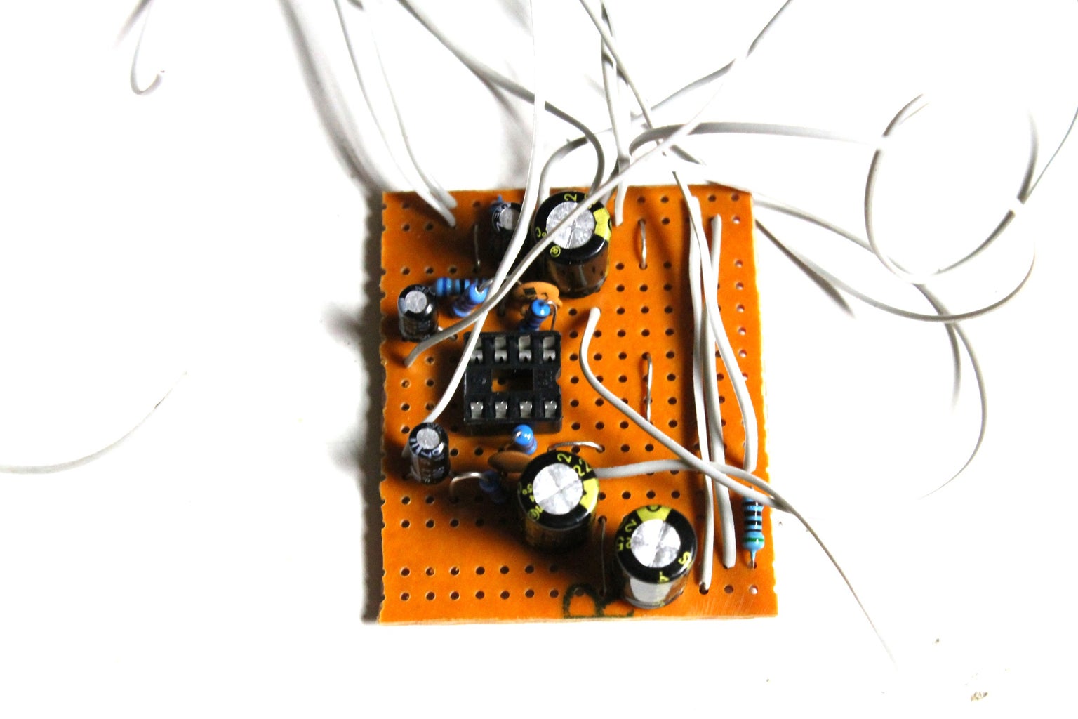
1. Solder an 18k resistor to pin 2 on the IC. The other leg solder to an open solder point on the prototype board
2. Next, solder the positive leg of a 4.7uf cap to the other leg of the 18k resistor. The other leg solder to a spare solder point on the board. This will later be connected to the potentiometer and output section of the amp.
3. Now you need to do the same thing for the other channel on your headphones. This time, add a 18K resistor to pin 6 on the IC. The ground leg on the cap solder to an open solder point on the prototype board
4. Solder the positive leg from a 4.7uf cap to the other leg of the 18K resistor – same as pin 2. Solder the ground leg to an open solder point on the prototype board
5. Connect pin 4 to ground
6. Connect pin 8 to positive
7. You also need to connect pins 3 and 5 together. I do this underneath the circuit with a
resistor leg.
Step 6: Making the Circuit - Part 4


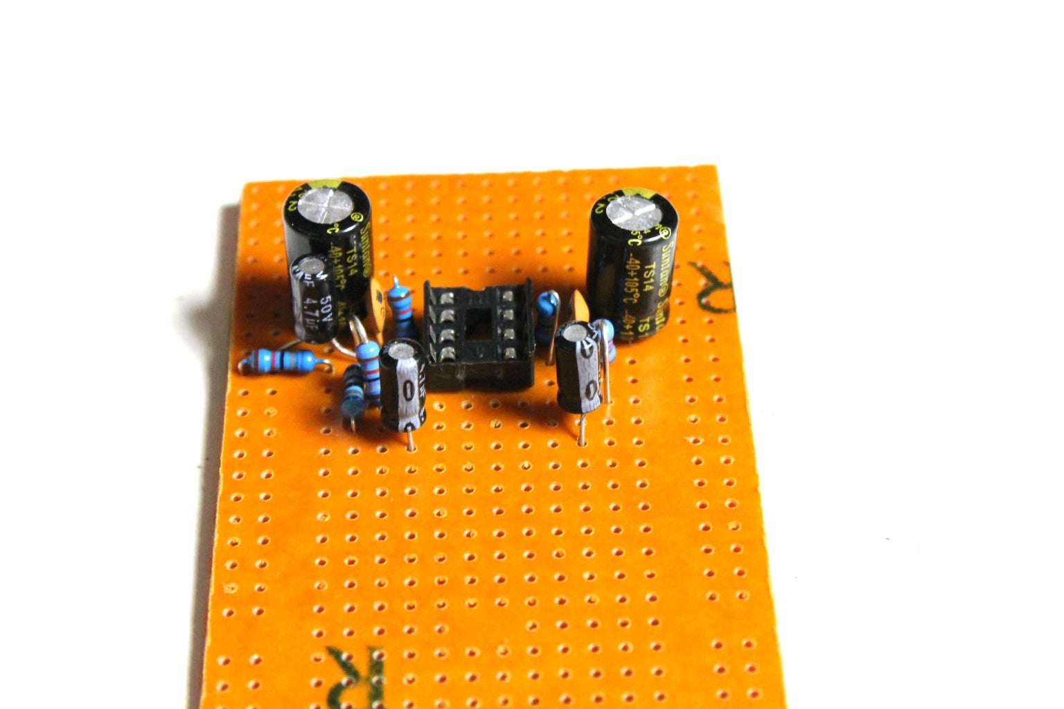
That’s all of the components connected. I later decided to add an LED as well so just follow the below if you want to do this as well.
Steps:
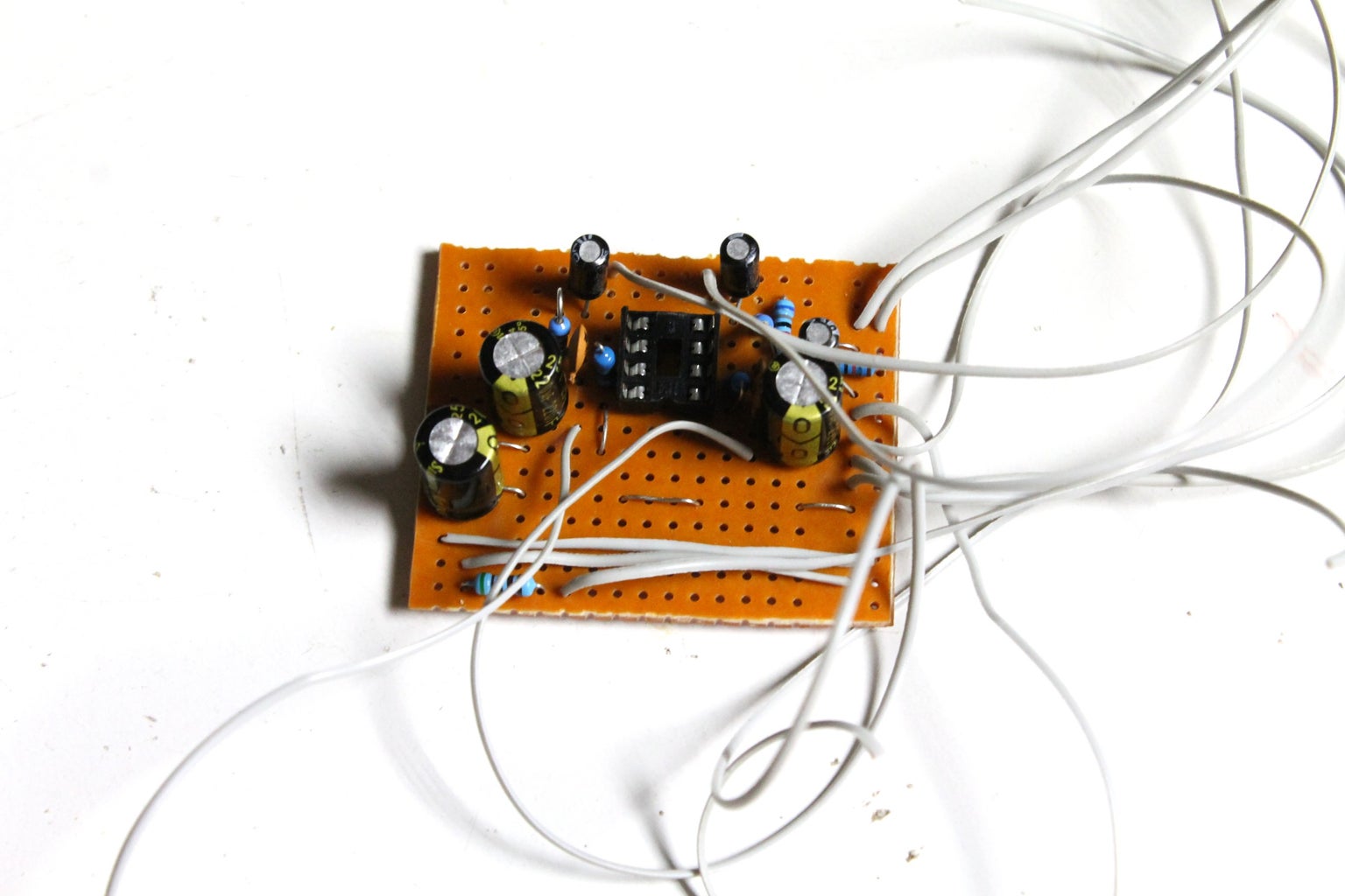
1. First connect both the ground and positive bus strips on the prototype board with some wire
2. Next, add 4 lengths of wire to ground bus strip
3. Add a couple of wires to the ground legs on the 4.7uf caps
4. Do the same to the ground legs on the 220uf caps
5. You also need to add a wire to each of the positive and ground bus strips for power
6. If you want to add an LED “on” indicator, solder a 20k resistor to ground and then to a spare solder point. Solder a wire to the other end of the resistor.
7. Lastly, trim the circuit board to size.
That’s it for the board, now it’s time to build the case
Step 7: Pick a Case


Picking the right case in my opinion, is just as important as getting the electronics working. It took me awhile to find just the right tin for this project, which a friend actually gave to me. Initially I made a couple of different ones out of wood but I didn’t go with a wood case in the end as it just wasn’t working for me.
If you are looking for an old tin case, then you can always try eBay. Just type in Tobacco tin and you’ll come across heaps of them. You can also use an Altoids tine which you can now buy in many different designs
Steps:
1. The most important thing about finding the right case is to ensure that you will be able to fit the battery and circuit inside. You’ll also need to add a couple of 3.5mm sockets, a switch and a volume pot to it so make sure you have a little wiggle room for all of the components
2. Place the circuit inside the case and if necessary, trim the edges so you can push it right up against the side of the case
3. If everything fits ok then you can start to drill all of the holes needed to add the components
Step 8: Adding the Auxiliary Parts to the Case


As there isn’t much room in the case, you will need to really think about where you add all of the axillary components. Don’t just start drilling holes into the case, place the circuit and battery inside it and think about the best spots to add the sockets etc. Remember, the amp will probably sit in your pockets so you need to think about having the sockets facing up etc.
Steps
1. Drill 2 holes for the 3.5mm sockets. Try to put these close together and have them so if the case is in your pocket, they will be facing upwards.
2. Drill a hole for the SPDT switch
3. Drill a hole for the potentiometer
4. You can’t see it in the images, but you also need to drill a small hole for the LED. Try to get this as close to the switch as possible.
5. Once all of the holes are drilled, you can then add all of the auxiliary parts to the case.
Step 9: Wiring-up the Circuit and Toubleshooting


It’s now time to solder the wires from the circuit board to the auxiliary parts on the case. This can be a little fiddly, especially if you gave a small case. Wires take up a surprising amount of room so make sure you trim them as much as you can before attaching them. You want to make sure though that you can lift the circuit board up and check underneath and problem solve if necessary.
Steps:
1. Place the circuit board into the case
2. Using the schematic as a reference, solder each wire to the corresponding component.
3. Trim the wires beforehand though and make sure that they are as short as possible. This helps to reduce the space wires take-up and can help with better sound quality (the less the distance between components, the shorter the signal has to travel.
4. Once you have everything connected, you are ready to test. Plug in a battery and turn on the switch. If the LED come on then that’s the first good sign. Now add a lead to the input and plug it into your phone (or MP3 player)
5. Plug your headphones into the output socket and play some music. Make sure, though you don’t have the volume turned right up on the amp.
6. If you can hear music, congrats you managed to make the circuit without any mistakes. If you hear nothing, then you’ll need to troubleshoot.
Troubleshooting
1. Check the solder joins on the prototype board and make sure none are cross soldered
2. Double check the wiring to the components and make sure that these are wired-up correctly.
3. If you only hear out of one speaker, check that you have connected the sockets correctly. Usually, the larger solder lug on the socket is ground. The other 2 are either the inputs or outputs. It doesn’t matter though in what order you wire these up to the prototype board. Also, make sure you have connected pins 3 and 5 together or only 1 speaker will work.
4. Make sure that you have connected the IC correctly. I managed to connect pin 8 to ground instead of positive.
Step 10:

Participated in the
Remix Contest


![Tim's Mechanical Spider Leg [LU9685-20CU]](https://content.instructables.com/FFB/5R4I/LVKZ6G6R/FFB5R4ILVKZ6G6R.png?auto=webp&crop=1.2%3A1&frame=1&width=306)


