

Introduction: All-In-One Portable Raspberry Pi Enclosure — Pi Terminal


Pi _Terminal is an all-in-one portable enclosure for the Raspberry Pi 4, featuring a 8 inch IPS screen, a low profile ice tower cooler, a UPS using two rechargeable 18650 lithium batteries and a HDMI switcher to use the display on it's own as a monitor.
The design was mainly inspired from these industrial retro CRTs. The goal wasn't to be the most compact, but rather to have spacious and flexible enclosure to expand and build more within.
I used Autodesk Fusion 360 to design all the parts and PCBs. I love how the mechanical and electronic spaces are seamlessly integrated to ensure aesthetics, form and fit from the first iteration.
Initially I started this because I needed a way to consolidate several of my RPI projects instead of having dedicated ones, it's almost impossible to get them at a reasonable price at the moment. I plan on adding some storage and a multi-boot configuration to group them all in one place using only one Pi.
Supplies

Electronics
- Custom PCBs — Order from PCBWay or download the gerbers from Github
- Raspberry Pi 4 Rpilocator
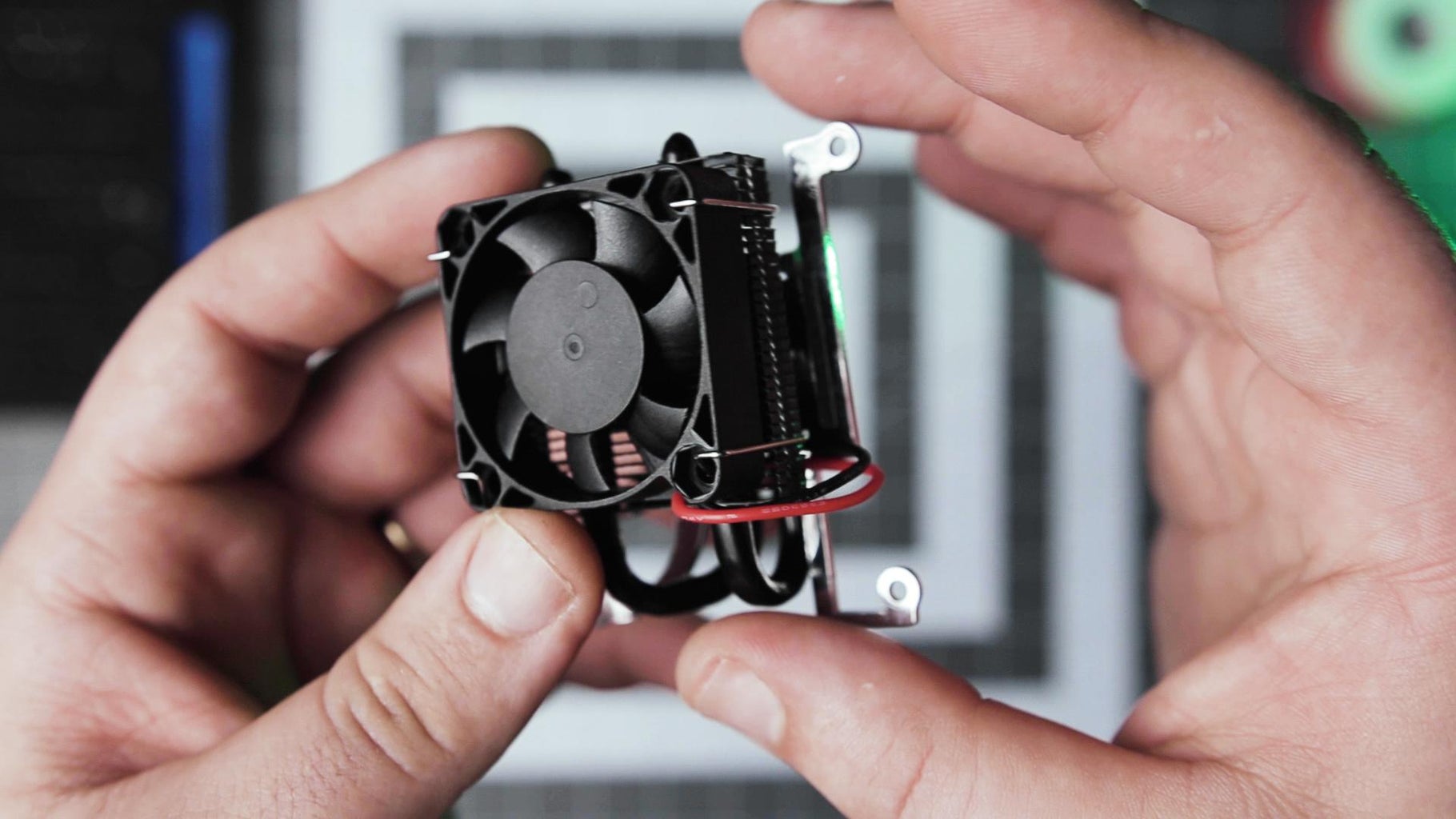
- Raspberry Pi Low-Profile CPU Cooler Amazon
- Pi-UpTime UPS 2.0 Amazon
- 2 × unprotected 18650 Li-Ion — 3400mAh
- IPS LCD 8 inch HJ080IA-01E with Driver Board AliexpressAmazon
- HDMI Switcher 2 in 1 Out Amazon
- Hook-up wire Amazon
- Dupont Connectors Amazon
- HDMI cables (Adafruit - Aliexpress mix and match connectors to make the needed cables)
- 1 × Micro HDMI to Standard Plug
- 1 × Micro HDMI to Standard Socket
- 1 × Standard HDMI Plug to Socket
- 1 × Standard HDMI Plug to Plug
- Micro to Micro USB cable (short)
- 3.5mm Audio cable (short)
Control Panel Digikey BOM
- 2 × 100 Ohms Resistors 0603 (1608 Metric)
- 2 × 4 Ohms 2 W Small Speakers
- 6 × Pushbutton Switch DPST-NO
- 1 × Pushbutton Switch DPDT
- 7 × Round Switch Cap
- 3 × Green LEDs 1206 (3016 Metric) Vf 2.1V
- 2 × 3.50mm Switched Headphone Jack
- 1 × Header Connector 20 position (2×10 - 2.54mm)
- 1 × Header Connector 4 position (2×2 - 2.54mm)
Power Adapter Digikey BOM
- 2 × 5.1 kOhms Resistors 0603 (1608 Metric)
- 1 × Rocker Switch SPST Panel Mount, Snap-In
- 1 × Header Connector 2 position (1×2 - 2.54mm)
- 2 × USB - C Receptacle Connector 24 (6+18 Dummy) Charging only
- 1 × 2 Position Terminal Block
- 1 × Jumper Connector (1×2 - 2.54mm)
- 1 × USB - micro B Receptacle
Hardware
- 21 × M2.5 × 3.4 mm Heat-Set Inserts McMasterCarr
- 8 × M4 × 8 mm Heat-Set Inserts McMasterCarr
- 1 × Tripod 1/4"-20 Heat-Set Insert, 0.3" Installed Length McMasterCarr
- 2 × Mini Pull Handles 3/4" Center-to-Center Width, 1/2" Projection McMasterCarr
- 4 × Thumb Screws M4 x 6 to 10 mm Long McMasterCarr
- 13 × Socket Head Screw M2.5 x 5 mm Long Amazon
- 3 × Socket Head Screw M2.5 x 8 mm Long Amazon
- 5 × Socket Head Screw M2.5 x 20 mm Long Amazon
- 3 × Flat Head M2.5 x 5 - 6 mm Long
- M2.5 Nylon Spacer Standoffs Amazon
3D printing and Finishing
- 1 × Spool of PLA filament Amazon
- Assorted Grits Sandpaper Amazon
- Glazing and Spot Putty Amazon
- Filler Primer (sandable) Amazon
- Spray Paint Amazon
- Flat Matte Clear Coat Amazon
Tools
- 3D Printer (minimum 200 mm × 200 mm build surface) Amazon
- Soldering Station/Iron. Amazon
- Helping hands Amazon
- Precision Screwdriver Set Amazon
- Wire stripper Amazon
- Crimping tools Amazon
- Isopropyl alcohol
- Sanding block
- Flux, Solder and heat shrink tubing
- Flush cutters, hobby knife, tweezers and pliers
⚠️ Some parts are optional and depend on the configuration you need. For example, if you use the UPS, you only need to populate the terminal block and 1 USB C socket in the power adapter, the same goes for the hardware and fasteners (further details below). You can adapt the build to suit your needs and remove any unnecessary parts.
Affiliate links may be included in the parts list. I may receive a small commission at no additional cost to you.
Step 1: Watch the Build Video
This video will give you an overview of the entire build to get a good idea of what's involved.
Step 2: 3D Printing


Grab the STLs from Thingiverse or directly from this page.
Just a heads up, this is a very long print compared to a quick weekend project, it's about 4 days of straight printing. In the video you can see how long each part took to complete. I spread them out over a week and had 1 failure and one almost 😬 where the support broke off mid-print. Luckily I was around to pause and hot glue it back to save the part.

Step 3: Finishing


It was the first time I tried this kind of finish and I must say that it makes a total difference but it requires considerable effort. It's up to you whether you want to go this route or if you're happy with the current state of the parts.
⚠️ With all the sanding and dust involved, I strongly advise doing this outdoors or in a well-ventilated area as well as wearing proper protective gear.
Post-processing
I started by lightly sanding all visible surfaces with a coarse 240 grit to knock down the layer lines, after that I wiped it down with isopropyl and applied a thin layer of glazing putty to fill most of the cracks and defects.
Once it dried, I went over it with 240 grit again, then 320 to further refine the surface. You can sand until you start to reach the high points on the PLA, this way only the dips and cracks are filled in and you don't alter the geometry of the model. Flat surfaces are quite easy, only the details and corners can be a bit tricky (patience).
Again, a proper wipe down with isopropyl and it's time to use the filler primer. This will help fill in and expose the smaller crack defects and will also reduce the amount of sanding needed.
I worked up the grits from 320 to 600 after the filler primer dried and I was ready to paint.
If you want you can still do more filling with glazing putty and more coats of filler primer. Rinse and repeat until you are satisfied with the smoothness of the surface.
Painting
Making sure the surface was clean and dust free, I applied 2 coats following the instructions on the can. Once it was completely dry after about 24h, I applied a matte clear coat to the visible sides to protect them.
Step 4: Soldering


There is few SMD parts to get out the way first in both the control panel (3 leds and 2 resistors) and the little power adapter boards (2 resistors)
Next, the switches and the rest of the TH components. You might need a set of helping hands to hold the boards steady while positioning the components.
Control board
Make sure the switches and audio jacks are aligned properly, there is a bit of play and if you solder them crooked the buttons will end up looking weird. ⚠️ Both of the headers are soldered pointing to the inside of the case.
Power Adapter (Option 1: with the UPS)
The jumper on the power adapter is shorted and you can supply power to the UPS from the terminal block with 20-22 awg wire or the USB C receptacle. The main rocker switch will be connected to the on-off jumper on the UPS.
Power Adapter (Option 2: no UPS, direct power to the Pi and screen)
The jumper on the power adapter is connected to the main rocker switch to control the power coming in. The Pi and the screen are supplied from the USB C and Micro receptacles or the directly from the the terminal block.
Speakers
Lastly, solder the speakers to the control board with the shortest length wire possible to be able to fit them inside the 2 allocated slots in the 3d printed spacer.
Step 5: Wiring
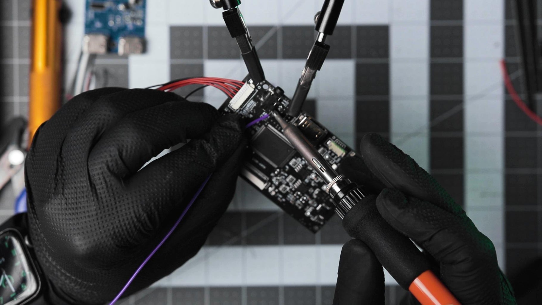

Starting with the HDMI switcher. I desoldered the existing switch and extended the pins on the board with 6 wires. Most of these things have an OnOn (DPDT) switch, which means you can't just leave it in place and extend connections.
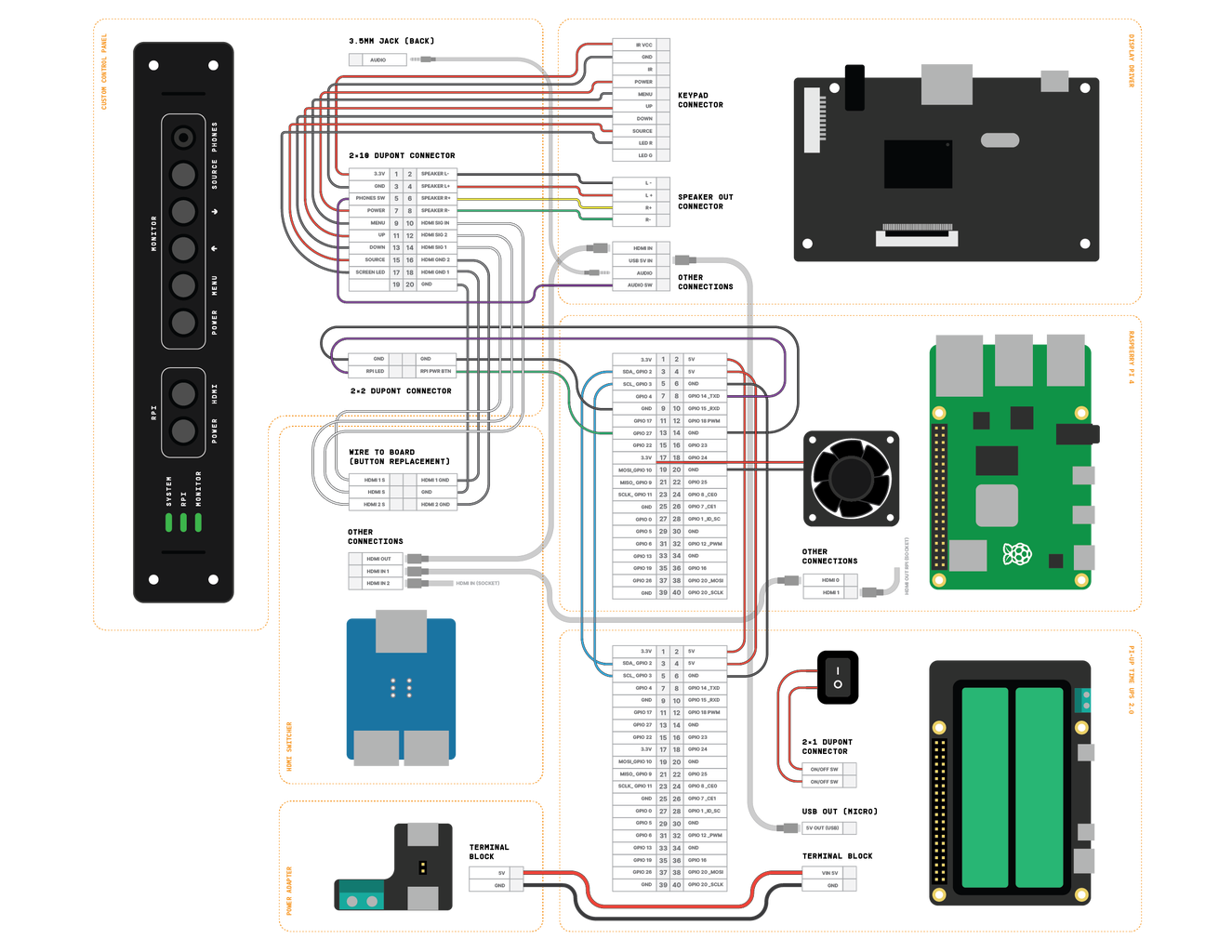
Next I soldered a wire to the audio jack switch on the display driver board since we are moving it to the front of the control panel. After that I prepared a 2 x10 dupont connector and marked the polarity with a sharpie to avoid connecting it to the wrong side. Then I crimped all 19 connections and started populating the connector, please refer to the wiring diagram (pdf below) or silkscreen markings on the back of the board. There is also a 2 x 2 dupont on the right side of the board for the RPI shutdown button and led.
Since I'm using the low profile ice tower, I can't stack the UPS on the Pi like a HAT, so we'll prepare a 5 wire dupont connectors for it and 2 wires with ferrule crimps to connect power from the adapter's terminal block. (There is also an option to use USB C to power the UPS)
⚠️ No need to connect the UPS now, we'll do it at the last step of the assembly.
At this point it's a good idea to test the control panel and make sure all the connections in the cable harness are ok before moving forward.
Attachments

Step 6: Assembly _1


It's time to install all the heated inserts and start putting this thing together.
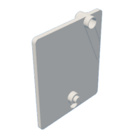
Start by placing the main bezel face down, insert the display followed by the back plate and secure it with the 6 M2.5 x 5mm screws. Then connect the driver board to the screen with the flat connector and only fasten the 2 screws on the right of the board (M2.5 x 5mm). Then place the small HDMI switcher support plate and only fasten the bottom screw (M2.5 x 8mm). Finally, put the HDMI switcher in place along with the remaining top screw (M2.5 x 20 mm)
Step 7: Assembly _2

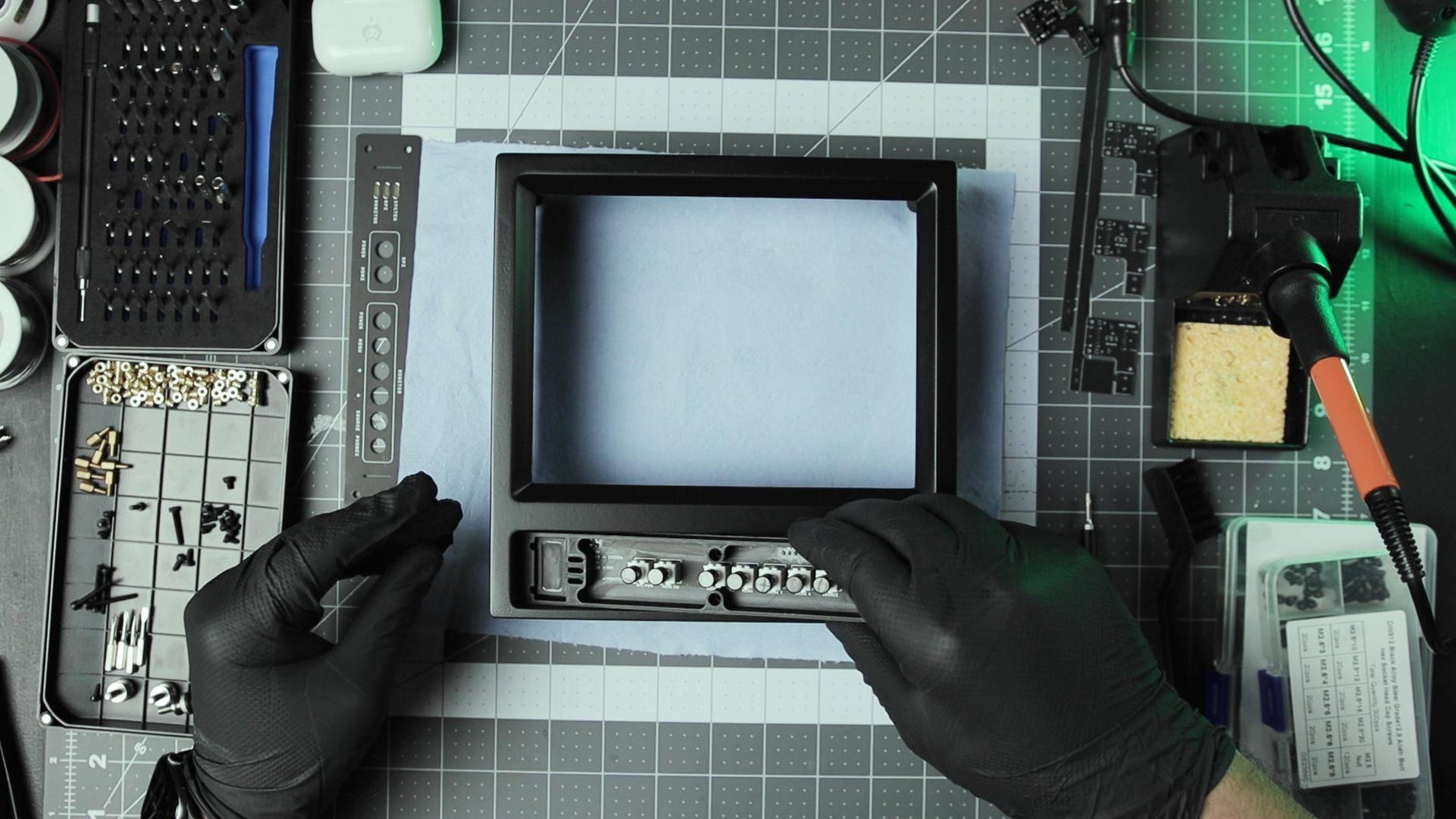


Snap the switch caps onto the buttons, then place the control panel PCB in the allocated slot, followed by the 3d printed spacer, paying particular attention to the two speakers and the 3 light pipes for the Leds. Fasten the 2 center screws only (M2.5 x 8mm) to secure the spacer on top of the PCB to the main bezel. Next, place the front panel PCB on the spacer and secure the 2 mini pull handles with 4 screws (M2.5 x 20mm) from the back.
We can now connect the cables to the control panel headers and screen before having more things in the way. You can always reach this part, it's just more convient this way.
Step 8: Assembly _3

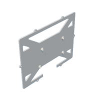
The bottom plate connects to the main bezel from the bottom with 3 flat head screws (M2.5 x 5mm).
⚠️ without the back cover in place, the bottom plate isn't particularly strong and you can break it easily. Since it's only connected at the edge and relies on the back shell to compress and support it from below.
Step 9: Assembly _4

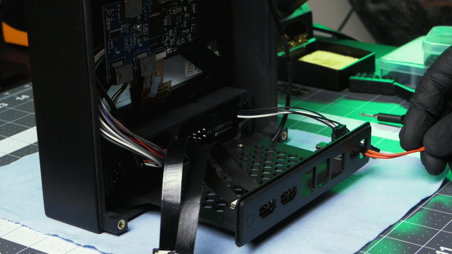
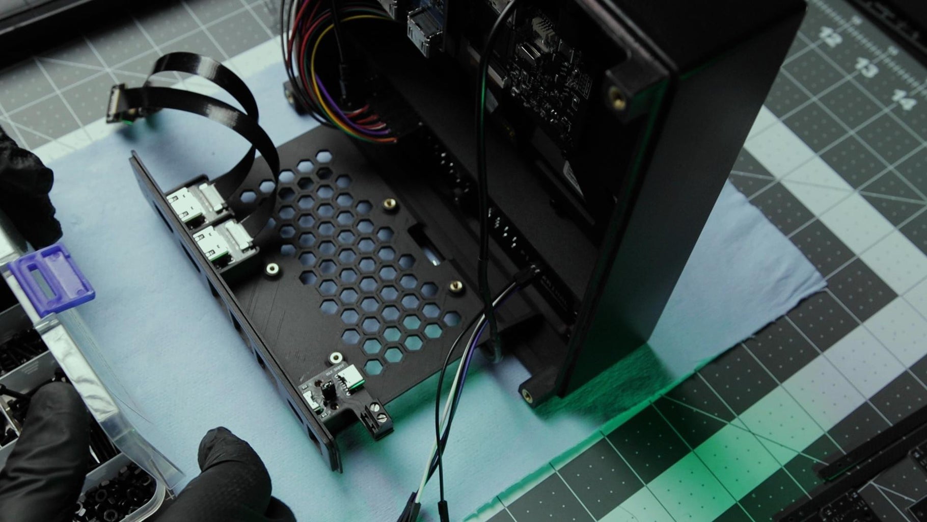
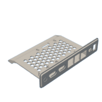
Start placing the component by snapping the 2 HDMI sockets in place, then secure the power adapter with 2 screws (M2.5 x 5mm) then snap in place the main rocker switch with the 2 wires to the back IO plate.
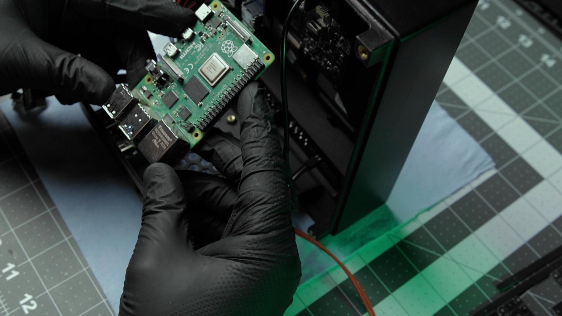
Next, fasten the Pi with 4 standoffs (M2.5) to the bottom plate, followed by the low profile ice tower. Stack couple more standoffs to secure the cooler to the Pi and to have enough clearance for the fan when mounting the UPS on top if you're using one.
The remaining HDMI cables can be connected to the sockets and the switcher (wiring diagram Step 5)
Before dealing with the UPS we can also connect the Ice tower fan and the 2x2 dupont cable from the control panel to the Pi's header.
Step 10: Assembly _5


Install the UPS
The Pi-Up time UPs don't ship with the Vin terminal block, so you need to solder one and connect the 2 wires from the power adapter or use the USB C and skip this step. Here is the recommended installation steps from the manufacturer:
- Removethe jumper J3 for the on/off switch
- Make sure the right battery chemistry based on battery you are planning to use. (Li-Ion / Li-PO4)
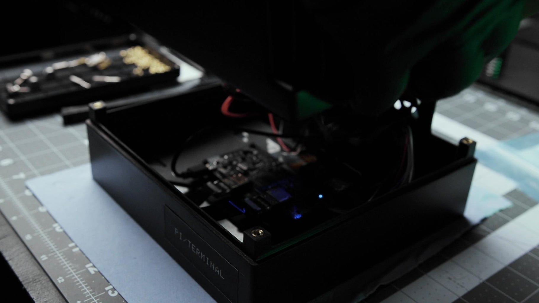
- Insert the 18650 cells in the battery holders following the right polarity. Improper battery insertion can damage the electronics. The Blue UPS light comes on when the UPS is functioning properly.
Source: alchemy-power.com
⚠️ Please read safety instructions and warnings before using or charging your batteries.
Rechargeable Lithium Ion batteries are potentially hazardous and can present a serious FIRE HAZARD if damaged, defective or improperly used.
With the main power switch in the OFF position connect it with dupont wires to the UPS on jumper J3.
Connect the Pi to the UPS using the 5 wire dupont cable prepared earlier.
Connect the screen Power In to the USB (micro) 5V out on the UPS.
(For reference: wiring diagram Step 5)
⚠️ Power requirements:
The UPS provides 2.5A max and requires 1.2A for charging current. I used the official Raspberry Pi 3A power supply and it works fine(ish) I only saw voltage drop bolts on boot when simultaneously charging the batteries and the screen is on. If you plan to connect power-hungry devices to the Pi, you may need to make some modifications.
Plug the USB C power supply into the port on the IO board. The green LED lights up indicating that the battery is charging. If there is no light, the battery is charged. When you unplug the USB C cable, the UPS LED turns blue, indicating that the UPS is in use.
That's for the assembly! it's time to close it with the back cover gently making sure the IO plate fits in the allocated slot. Thread the 4 thumbscrews (M4 x 6-10mm) into the corners and voilà.
Step 11: Configuration
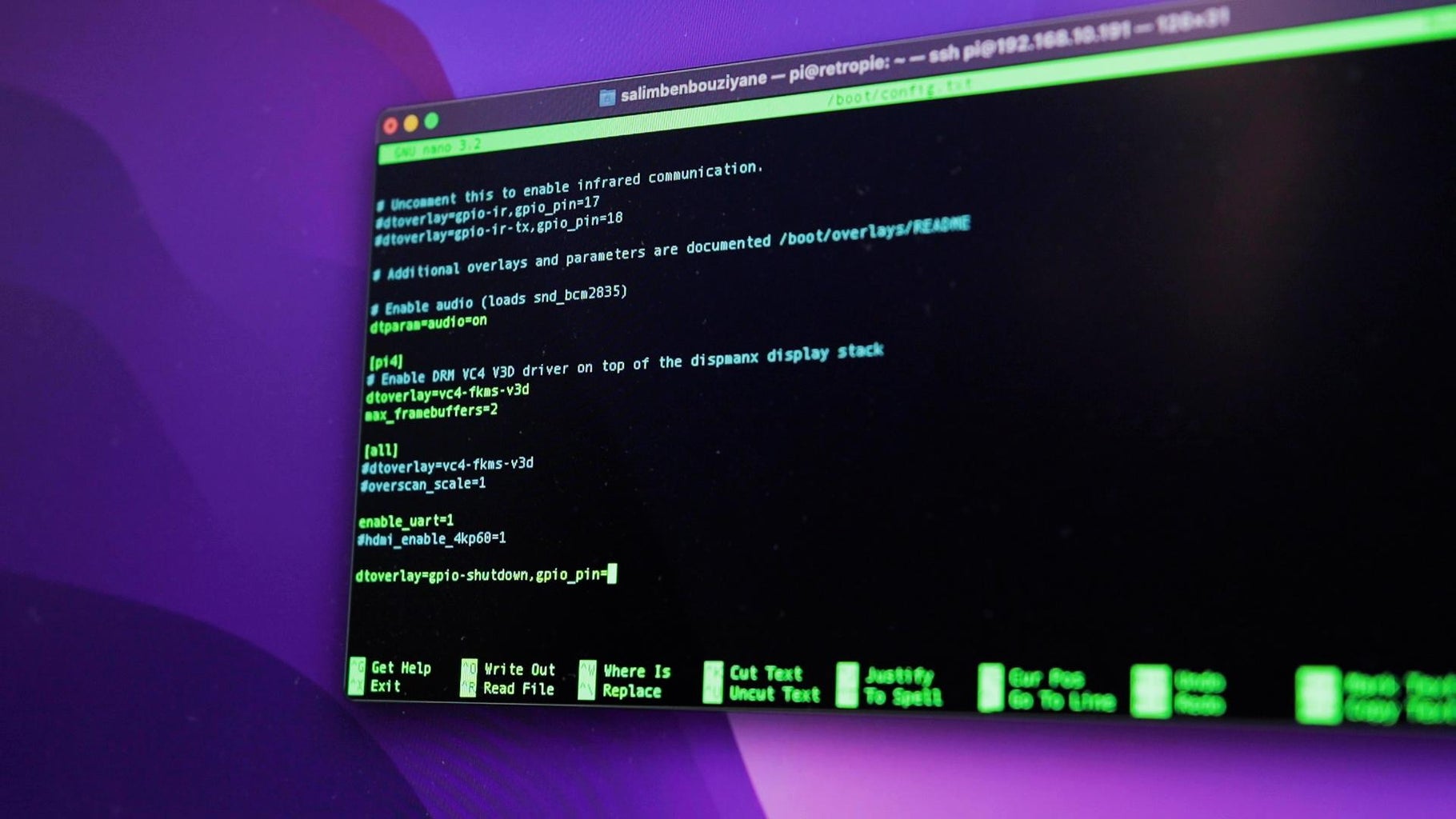
To be able to shutdown the Pi with control panel button we need to add following dtoverlay in /boot/config.txt
dtoverlay=gpio-shutdown,gpio_pin=27
by default the GPIO shutdown is on the GPIO 3 but I connected the UPS to I2C using that since it was closer. that's why I changed the pin to 27. There is a lot of different ways to implement this and you can customize it to your needs.
Once the Pi is turned off it continues to draw some power so it's a good idea to flick the main power switch off to minimize battery consumption when it's not plugged.
On the alchemy power website there is some example scripts to monitor the voltage via I2C and turn off the Pi when the batteries are nearly dead.
Step 12: Done


Thank you for sticking around until the end!
This was a lot of fun to make and I enjoyed the process. There is certainly a lot of improvements to be made. I'd love to hear your suggestions in the comments below.
I have a lot of ideas and I plan on making more projects like these Follow me for more

![Tim's Mechanical Spider Leg [LU9685-20CU]](https://content.instructables.com/FFB/5R4I/LVKZ6G6R/FFB5R4ILVKZ6G6R.png?auto=webp&crop=1.2%3A1&frame=1&width=306)


