

Introduction: Materials and Calibration

More by the author:


About: Autodesk Technology Center San Francisco is a hub for research, development, and demonstration of new manufacturing technologies and workflows relating to configurable microfactories.
LOAD STOCK
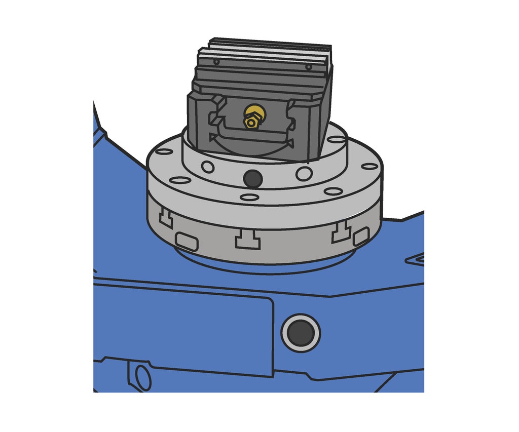
Install vise in machine.
- Press Door Unlock.
- Carefully wipe chips from receiver plate and bottom of vise.
- Set vise on receiver plate.
- Tighten front bolt to 30 Newton-meters using a torque wrench.
Install stock in vise
- Ensure 4th and 5th axes are locked.
- Center stock in vise.
- Lang vises have tick-marks on the front edges of the jaws which can be used as a reference.
- Tighten to 100 Newton-meters (70 Foot-pounds) using a torque wrench.
- Lang 3-jaw chucks should not be tightened more than 70 Newton-meters (50 Foot-pounds).
- Close the door.

CHECK WORK COORDINATE SYSTEM
Because Work Home is set to the top center of the Lang receiver plate, you don’t need to probe your stock. As long as the receiver plate is not moved for a custom project, G54 will not change.
- Follow these steps to ensure the G54 coordinates inside the machine are correct.
- On display, under Running, select Work Crd.
- Ensure G54 has a green check next to it.
- Compare the G54 (X, Y, and Z) coordinates with the numbers recorded outside the machine.
- If the numbers are different, consult shop staff.
- Take a picture of G54 on the controller so that you can ensure consistency for multiple-day operations.
Step 1: Tool Offsets
SET THE TOOL LENGTH OFFSETS
Matsuura library tools are stored inside the tool carousel. Before running a program, you will call up each tool to verify the number and measure the tool length offset.

Perform a tool change
- Press MDI.
- Turn key to AUTO.
- On display, under Running, select NC Opera.
- Type T[tool number]M6.
- The G-code will appear in the command line.
- Press EOB.
- Press INSERT.
- The G-code will move to the program section of the screen.
- Turn the Rapid Rate to 10%.
- Press CYCLE START.

Check tool.
Verify that the tool in the machine is the same as the one in the library.
- Press Door Unclamp and open door.
- Check the tool number engraved on the tool holder.
- If the tool numbers do not match, check with shop staff.
- Close door.
Measure tool.
- Type G101.
- This command will measure the tool currently in the spindle.
- You will use G101 for every tool in your program.
- Press EOB.
- Press INSERT.
- Press CYCLE START.
- The machine will use a laser to measure the length of the tool.
Repeat these steps for each tool in your program.


