

Introduction: Mechanical Linear Actuator


I will guide you through creating a linear actuator for your Arduino or robotics project at home. But first, let's start with a brief introduction to what a linear actuator is.
A linear actuator is a mechanical device that converts energy (typically electrical, hydraulic, or pneumatic) into linear motion. It's used in a wide variety of applications to move or control a mechanism or system, such as in robotics, industrial machinery, and consumer electronics.
The basic principle of a linear actuator is relatively straightforward: it uses some form of energy to produce a straight-line movement, which is different from the rotational motion produced by conventional motors. Here are the main types of linear actuators:
- Electric Linear Actuators: These are powered by electric motors and are known for their precision and control. They are commonly used in applications where accurate positioning is crucial.
- Hydraulic Linear Actuators: These use hydraulic fluid pressure to create motion and are often found in heavy-duty applications, such as construction equipment and manufacturing machinery, due to their ability to exert large forces.
- Pneumatic Linear Actuators: These operate on compressed air and are typically used in applications requiring quick, repetitive movements.
- Mechanical Linear Actuators: These convert rotary motion into linear motion using mechanical components like screws or gears.
Here I am going to make Mechanical linear actuator.
enjoy!
Supplies

Items that we need
- TT gear motor
- M6 Threaded rod(length:15cm)
- M6 Nut
- Aluminum tube(Inner diameter:8mm , length:15.5cm)
- 1/2 inches PVC pipe(length:)
- Super glue
Tools that we need
- Drill
- Piler
- Hot glue gun
- Soldering Iron
- 3D printer
- Mini grinder
- Scissor
- Digital vernier caliper
- Soldering iron
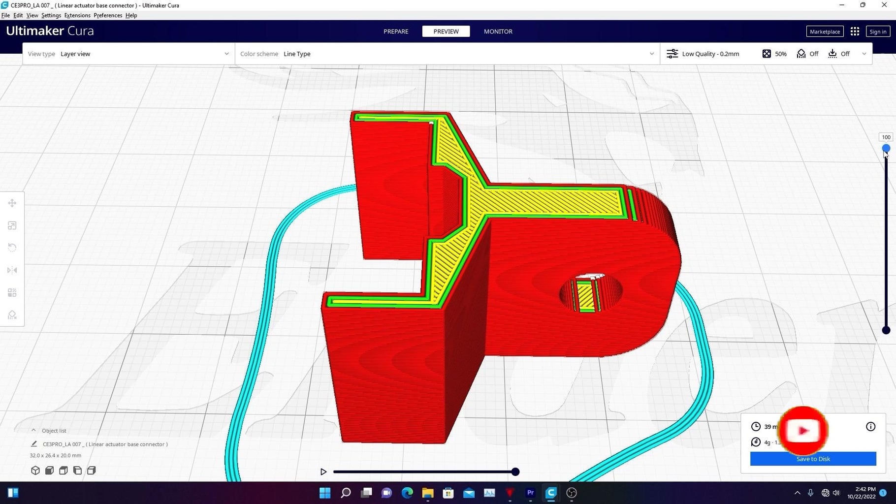
3D printed parts
You will also need to 3D print a few parts for this project. You can print them by using PLA with 100% infill rate and 0.1/0.2mm layer height. ( make sure your 3D printer prints to the very correct dimensions.)


Step 1: DC Motor Part


- Cut the excess part of TT gear motor.
- Take an M6 threaded rod and cut it into 15-centimeter lengths
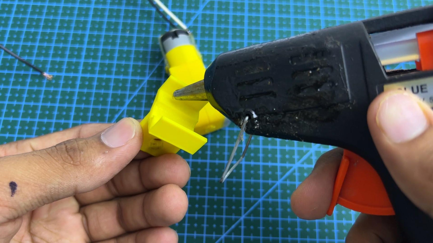
- using the TT gear motor and thread bar connector, fix the threaded bar to the gear motor's outer shaft
- after fixing, heat the 3D-printed part and deform it by by applying pressure using a piler
Step 2: Prepare the Middle Part


- insert the nut into the 3D-printed part.
- Take an aluminum tube with an 8mm inner diameter and cut it into 15.5cm lengths.
- fix the aluminum tube to the 3D-printed part
- After fixing, heat the 3D-printed part and deform its ends to ensure proper fixing.
- make a hole at the top of the aluminum tube
Step 3: Prepare the Outer Casing


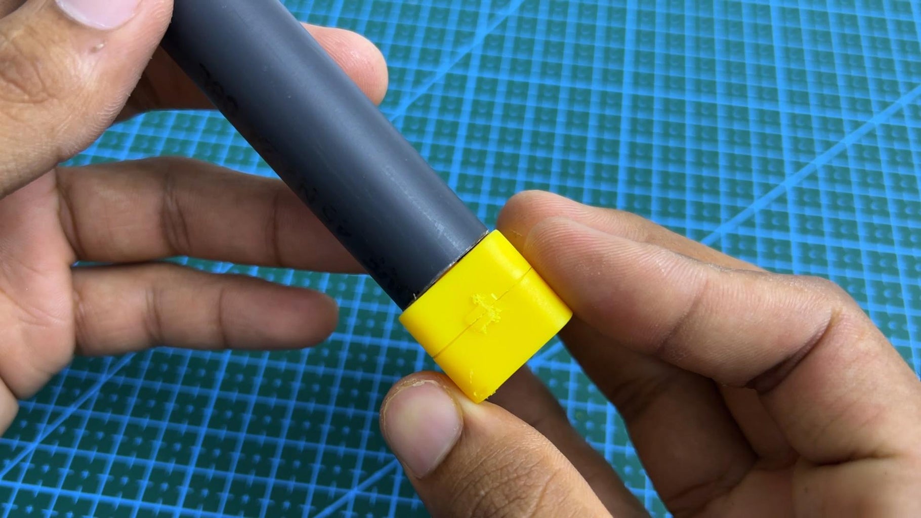


- take PVC pipe with a 1/2-inch diameter and cut it into 16cm lengths
- measure the necessary diameters and prepare a round part for the end of the pipe.
- fix the above part to the pipe by applying some super glue
- center the PVC pipe in the correct way and attach it to the gear motor's casing using hot glue
Step 4: Mark the Top and Bottom Limits


- identify the limitations of moving the aluminum tube inside the PVC pipe and mark its top and bottom limits. (For a clearer understanding, watch the attached video demonstrating the construction process.)
- we should only move the Aluminum tube between these limits. When the top mark and bottom mark reach their respective ends, we should stop the motor.
Step 5: Final Part


- attach the 3D-printed supporter to the gear motor's body using hot glue
- our linear actuator is ready! For a better understanding, I recommend watching the tutorial video given below
- You can get an idea about How much weight this can lift by watching this.
Step 6: Improved Version
Here, you can learn how to build a linear actuator equipped with top and bottom end limits. This actuator automatically stops at its top and bottom positions, eliminating the need to monitor its operating range. It handles this automatically.


![Tim's Mechanical Spider Leg [LU9685-20CU]](https://content.instructables.com/FFB/5R4I/LVKZ6G6R/FFB5R4ILVKZ6G6R.png?auto=webp&crop=1.2%3A1&frame=1&width=306)


