

Introduction: Open the Gate With Your Phone! - DIY Smart Gate (without Modifying the Gate)


Hi, I am Giovanni Aggiustatutto and welcome on this Instructable! Today we will see how we can open our house gate with our phone. In fact, in my apartment building there is an electric gate that opens with the classic radio remote control. By modifying this remote control we will be able to control the gate with the app on our phone, avoiding having to carry the remote control with us all the time. The most important thing is that we will only modify the remote control, without touching anything on the gate, and therefore without risking damaging it. But now let's get started!
To see more details about this project, watch the full video on my YouTube channel (it has English subtitles).
Supplies


To make this project I used:
- Remote control of my gate
- ESP8266 board Wemos D1 mini
- 5V relay
- BC548 transistor
- Perfboard
- 12V remote controlled relay (Amazon link)
- 5V voltage regulator
- 470 ohm resistor
- 2 LEDs with 680 ohm resistor
- Diode
- 2 terminal blocks
- 13 M4x35 mm screws with nuts
- White PLA filament
- Various cables
- Two 12V power supplies
Tools:
- 3D printer (optional, used only to make simple boxes)
- Soldering iron
- Hot glue
Step 1: Modifying the Remote


As I told you before, my gate opens with a simple remote control. Today's goal is to create a system that can press the remote control button when we give the command from the app. First, I disassembled the remote control. Inside we have the circuit board and a battery. On the two contacts of the battery there are 12V, but what happens if I connect a power supply instead of the battery? So I connected my 12v bench power supply to the two contacts, and the remote control LED lit up, so it could work.
At this point I removed the battery contacts and soldered two wires to the PCB, being careful to connect positive and negative as they were connected with the battery. Then I soldered a wire between the two contacts of the remote control button, so that as soon as the remote is powered it immediately sends the signal to open the gate. I went to the garage (near the gate) and when I connected the 12v to the remote control the gate opened. So the basic idea works, now it remains to connect the remote control to the home automation and then control it from the phone.
Step 2: Smart Relay


As we have seen to open the gate we only need to give power to the remote control for a few seconds. So you could just use a smart relay like a Shelly relay to give power to the remote from the app. This solution is really simple and doesn't require to have Home Assistant, since smart relays generally have their own cloud service included. If you choose this option, if you have a 230V smart relay, connect to the input of the relay the mains voltage, and to the output of the relay the power supply to which is connected the remote control of the gate. Instead if you have a 12V smart relay, connect the input to the output of the power supply, and the output directly to the remote.
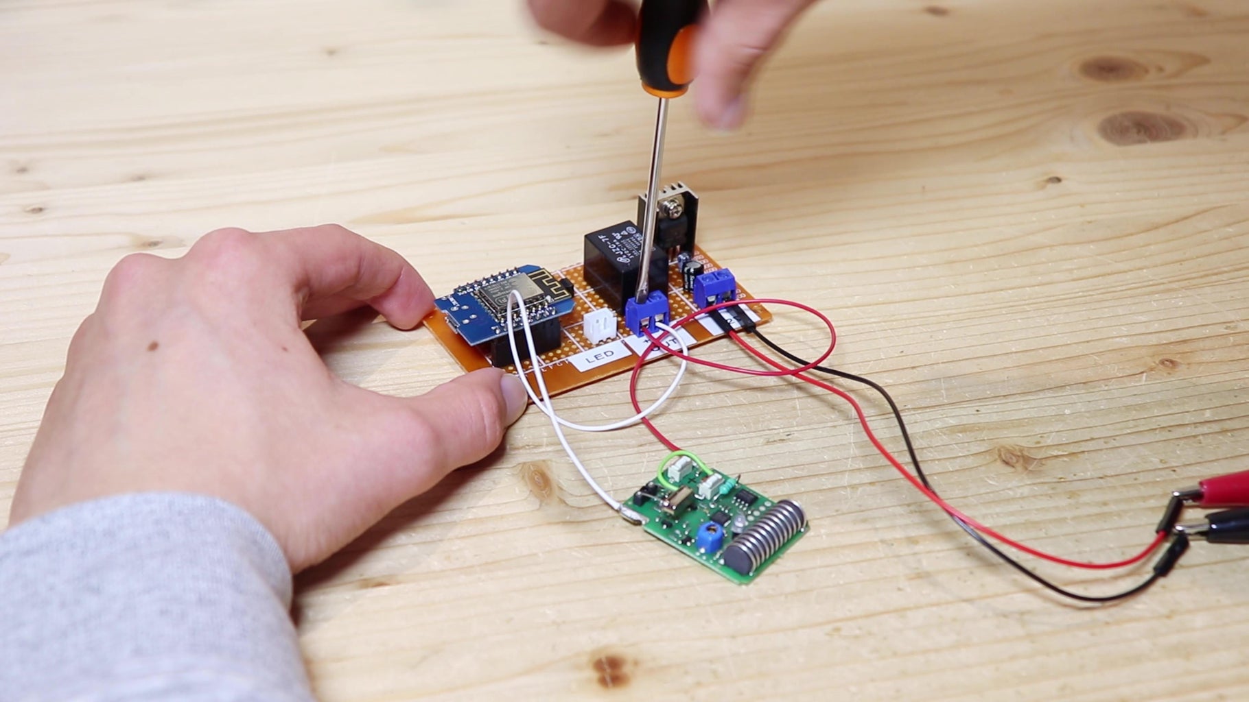
As always I wanted to complicate my life by making everything from scratch. So I cut a piece of perfboard, on which I put an ESP8266 board. This board is actually very similar to an Arduino, but it has WiFi connection, which will be very useful for us to connect it to Home Assistant. On the perfboard I also put a relay and a linear voltage regulator to bring the 12V with which we will power everything to 5V for the ESP8266. However while testing the circuit I noticed that it heats up a lot and it is very inefficient. So I suggest using a step-down regulator, that is still cheap but way more efficient. Then I soldered a transistor to give current to the relay, and a resistor to connect the base of the transistor to a pin on the ESP8266. To the coil of the relay I connected a flyback diode, to prevent the current left on the coil from damaging the other components when the relay is turned off. As a last thing, I put two terminals for the 12V power supply and for the output controlled by the relay, which will go to the remote control. I made all the connections under the board following the wiring diagram that you can find below, and we are done.
Attachments

Step 3: Connecting the ESP8266 to Home Assistant


If you have decided to use a pre-made smart relay, like a Shelly relay, just ignore this step, because you can use its own app to control the relay and the remote control connected to it.
To connect the ESP8266 to which is connected the relay to my smart home I will use Home Assistant with the ESPhome add-on. With the Home Assistant app I will be able to power the remote control and so open the gate.
Home Assistant is a platform with which we can manage all our smart devices from a single interface. Home Assistant works in our local network, so we need a device to run it: we can use a Raspberry Pi or, like I do, an old Windows PC with Home Assistant running on a virtual machine. To control the relay from your smartphone you can download the Home Assistant app. To connect from outside the local network I'm using the Nabu Casa Cloud, which is the simplest solution but it's not free. There are other solutions but they are not totally safe.
To connect the ESP8266 to Home Assistant we will use ESPhome. ESPhome is an add-on that allows us to connect ESP boards to Home Assistant via WiFi. To connect the ESP8266 to ESPhome you can follow these steps:
- Install the ESPhome plugin in Home Assistant
- On ESPhome's dashboard, click on New device and on Continue
- Give your device a name
- Select ESP8266
- Copy the encryption key that is given, we will need it later
- Click on EDIT to see the device's code
- Under the name of the board you've chosen, write the type of board; if you used the same board as me, it will be:
esp8266:
  board: d1_mini
- Under wifi, insert your wifi ssid and password
- To make the connection more stable, you can give the board a static IP address, with this code:
wifi:
  ssid: yourssid
  password: yourwifipassword


  manual_ip:
    # Set this to the IP of the ESP
    static_ip: 192.168.1.61
    # Set this to the IP address of the router. Often ends with .1
    gateway: 192.168.1.1
    # The subnet of the network. 255.255.255.0 works for most home networks.
    subnet: 255.255.255.0
- At the end of the code, paste this one:
output:
  - platform: gpio
    pin: GPIO13
    inverted: true
    id: 'relay'


lock:
  - platform: output
    name: "Cancello"
    id: gate
    output: 'relay'
    on_unlock:
      - light.turn_on: led
      - delay: 5s
      - lock.lock: gate
      - light.turn_off: led

light:
  - platform: status_led
    id: "led"
    pin:
      number: GPIO12
      inverted: false
This code is quite simple, and it creates a lock entity that you can put on Home Assistant frontend. When the lock is "unlocked" it turns the relay (and so the remote control that opens the gate) on for 5 seconds and then it turns it off, showing the gate ad "locked" again. I also put an LED that not only shows when the remote control state, but also the WiFi connection.
- Under esphome paste the on_boot code, as it will "lock" the gate immediately as the ESP8266 turns on, because otherwise it opened the gate when I plugged in the ESP8266 (maybe there are better solutions)
esphome:
  name: smart-gate-opener
  on_boot:
    priority: 600
    then:
      - lock.lock: gate
In the end the code should look like this, but not paste directly the code below, because to every device is given a different encryption key.
esphome:
  name: smart-gate-opener
  on_boot:
    priority: 600
    then:
      - lock.lock: gate


esp8266:
  board: d1_mini


# Enable logging
logger:


# Enable Home Assistant API
api:
  encryption:
    key: "***"


ota:
  password: "***"


wifi:
  ssid: yourssid
  password: yourpassowrd


  manual_ip:
    # Set this to the IP of the ESP
    static_ip: 192.168.1.65
    # Set this to the IP address of the router. Often ends with .1
    gateway: 192.168.1.1
    # The subnet of the network. 255.255.255.0 works for most home networks.
    subnet: 255.255.255.0


  # Enable fallback hotspot (captive portal) in case wifi connection fails
  ap:
    ssid: "***"
    password: "***"


captive_portal:


output:
  - platform: gpio
    pin: GPIO13
    inverted: true
    id: 'relay'


lock:
  - platform: output
    name: "Cancello"
    id: gate
    output: 'relay'
    on_unlock:
      - light.turn_on: led
      - delay: 5s
      - lock.lock: gate
      - light.turn_off: led


light:
  - platform: status_led
    id: "led"
    pin:
      number: GPIO12
      inverted: false
- After the code is complete, we can click on Install, connect the ESP8266 to our computer with an USB cable and follow the instructions on screen to upload the code
- When the ESP8266 is connected to the WiFi, we can go to the Home Assistant settings, where we will probably see that Home Assistant has discovered the new device
- Click on configure and paste there the encryption key you have copied before.
Then we need a card to control the lock via the Home Assistant frontend. I used one from the Mushroom cards, which are beautiful and very simple to set up. Unfortunately Home Assistant has not this card in the ones already installed.
Step 4: Testing the Circuit


When I press the unlock button on Home Assistant page the relay turns on for 5 seconds and then turns off. Now to test the circuit I used an LED bulb, but at the output then will be connected the gate remote control modified as we saw before.
I put the circuit with the remote control connected on the balcony, pressed the button on the app, the remote turned on, but the gate did not open.
Maybe I could have thought about it earlier, but the gate is too far away from my apartment, and the remote control range is not enough to reach the gate. However, if your apartment is near enough the gate, the project could already work fine.
Step 5: Increasing Remote Control Range


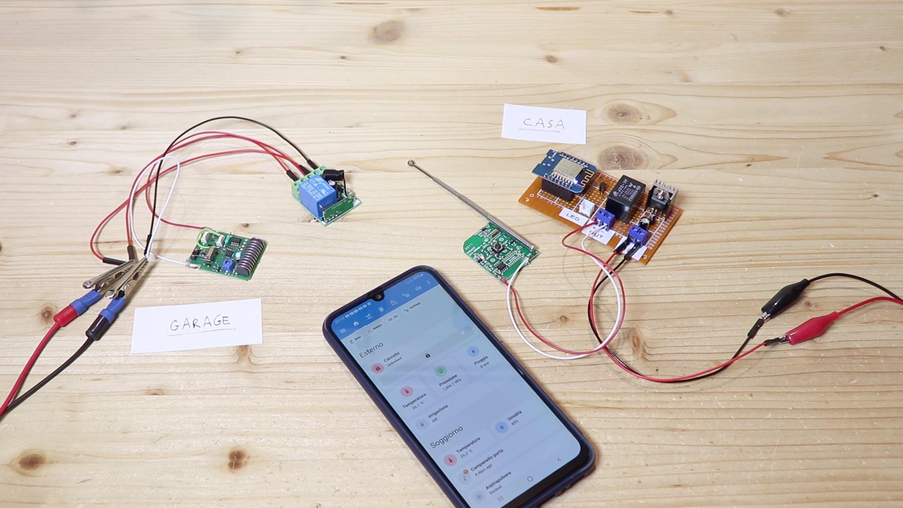
I thought about the problem I had with the remote signal not reaching the gate for a while and thought that from my garage the remote control works without any problem, since the garage is nearer the gate. The problem is that the garage doesn't get WiFi from my apartment, so I couldn't move the whole circuit there.
So I bought a small relay controlled by another remote control. The board with the relay has terminals for the 12V power supply and for the three relay contacts, and we will use the normally open and the common. The relay is set to momentary, so that the relay turns on when you press the button on the remote control, and it turns off when you let go of the button. My idea is to put the relay remote control in the house connected to the relay controlled via WiFi. Instead, the relay controlled by the remote control will be in the garage, and the gate remote control will be connected to the relay. That way as soon as I press the button on the app the first remote sends the signal to the relay, which then activates the gate remote.
Step 6: Connecting the Remote to the Relay


The relay remote control also runs on a 12V battery, so I made the same changes as the other remote so that when the remote is powered on with a power supply it starts sending the signal to the relay, turning it on. Then I connected the relay remote to the smart relay we have just made. I also connected the positive of the remote of the gate to the normally open of the relay controlled by the other remote. I connected a power supply to the power input of the relay and I brought the positive to the COM of the relay and the negative to the negative of the remote.
After I connected everything, I put the smart relay with the remote of the relay in my apartment and the relay with the remote of the gate in my garage. When I clicked the button on the app the gate opened, so the circuits work. Now I want to make these circuits look more like a finished product.
Step 7: Smart Relay Enclosure


So the circuit works, now we just need to create boxes in which to mount the various parts. To mount the smart relay and the remote control of the relay that will stay in the garage, I 3D printed two boxes with their lids (STLs below). The boxes have holes to mount cable glands. To power the circuit in the garage and the one in the house, I recovered these two 12V power supplies. I connected the power supply to the input terminals of the relay, letting the cable pass trough the cable gland. Then I connected a 2-pin cable to the 12V output of the smart relay, and connected the other end to the remote control of the relay that will be put in the garage. I put the remote in the other 3D-printed box. The remote control is placed away from the ESP8266 to avoid interference with WiFi. On the lid of the first box I put an LED to indicate the connection status, and I connected it to the board with a JST connector. I closed both the boxes with M4 screws and nuts.
Initially put the ESP8266 and the remote control on the balcony to have a better connection with the relay in the garage, but since the remote control of the relay has a long range I then put the two boxes inside home, where they don't risk to get wet.


Step 8: Mounting the Circuit in the Garage


The remote controlled relay and gate remote control will be put on the garage door, to have better signal reception from the remote that's in the apartment. To mount them on the garage door, I designed and 3D printed a little box. I redid the connections between the relay and the remote control so that they would be more compact, and I also soldered a connector for the supplying power to the circuit. I also wanted to have a button to open the gate directly from the garage, so on the connector I also carried the power for the remote control.
To the connector I connected a 3-pin spiral cable, that will extend when the door is opened and become shorter when the door is closed, to prevent the cable from going into the mechanism of the door.
The cable coming from the connector goes into another 3D-printed box along with the power supply cable. On the lid I put a button to open the gate and an LED to indicate whether the relay receives the signal. The button is connected between the positive of the power supply and the wire that goes to the positive of the remote. The LED is connected between the positive of the remote and the negative, with a resistor to limit the current to a few milliamps. At this point I mounted the small box with relay and remote control on the garage door, running the cable through the grilles. I secured the little box with a bolt and nut placed behind the door. Then I mounted the box with the button on top of the garage electrical outlet with zip ties, and closed the lid of the box. Finally I plugged the power supply in.
Smart gate receiver


Step 9: It Works!


I immediately went to see if everything worked, so I opened the Home Assistant app and pressed the button to open the gate. When I saw that everything worked I was quite surprised, because I would have expected there to be other problems. This project will be very useful for me because I don't have to always bring the remote control of the gate with me, since I can open the gate with my smartphone.
I hope you found this guide useful or at least interesting, and we will see in the next Instructable.
To see more details about this project, watch the video on my YouTube channel.


