

Introduction: Select Color Display for ESP32


This instructables show something about selecting a color display for your ESP32 project.
The content is intended to be updated from time to time, I will add more details if I found new display or library update. You can also help me enrich the content by leaving comments below.
Step 1: Why Add a Display?

You can run various IoT projects prefectly without any display. But not all IoT project only feed data in single direction (IoT to server), some IoT also gather real time information from the server for displaying.
My previous instructables, ESP32 Photo Clock is am example, it download a current minute photo from the Internet, decode the JPEG photo and display it.
There are various real time information in your server or Internet, such as all rooms temperature in your home, server CPU usage, weather forecast, news, stock price, your downloading file is done, your Youtube channel views :>
Step 2: Ok, Then Why Color Display?


Many Arduino projects use monochrome display, one of the reason is the limited resources of a MCU. 320 pixels width, 240 pixels height and 8 bits color for each RGB color channel means 230 KB for each full screen picture. But normal Arduino (ATmega328) only have 32 KB flash and it is time consuming (over a second) to read data from SD card and draw it to the color display.
ESP32 have changed the game! It have much faster processing power (16 MHz vs 240 MHz dual core), much more RAM (2 KB vs over 200 KB) and much more flash (32 KB vs 4 MB), so it is capable to utilize more color and higher resolution image for displaying. At the same time it is capable to do some RAM hungry process such as Animated GIF, JPEG or PNG file decoding, it is a very important feature for displaying information gathered from the internet.
Step 3: Serial Peripheral Interface

Color display have many type of interfaces: Serial Peripheral Interface (SPI), 6-bit, 8-bit, 16-bit, 18-bit and 24-bit parallel interfaces and also NeoPixel!
SPI dominate the hobby electronics market, most likely because of fewer wire required to connect. Most display in my drawer only have SPI pins breaking out, so this instructables focus on SPI display and a few 8-bit display.
Note:
NeoPixel matrix is a very special type of color display. If you are interested in NeoPixel matrix display, here are some of my instructables using it:
https://www.instructables.com/id/Display-Colorful-...
https://www.instructables.com/id/ATtiny13A-NeoPixe...
https://www.instructables.com/id/IoT-LED-Matrix/
https://www.instructables.com/id/IoT-LED-Cheering-...
https://www.instructables.com/id/IoT-LED-Sign/
Step 4: Hardware & Software

There are 2 parts to be considered while selecting a color display for ESP32.
Hardware
There are various color display for hobby electronics: LCD, IPS LCD, OLED with different resolutions and different driver chips. LCD can have higher image density but OLED have better viewable angle, IPS LCD can have both. OLED have more power efficient for each light up pixel but may have burn-in problems. Color OLED operate in 14 V, it means you need a dedicate step-up circuit, but it is not a problem if you simply use with a break-out board. LCD in most case can direct operate in 3.3 V, the same operating voltage as ESP32, so you can consider not use break out board to make a slimmer product.
Software
Software support on the other side also influence your selection. You can develop ESP32 program with Arduino IDE or direct use ESP-IDF. But since ESP-IDF did not have too much display library and not much display hardware supported, so I will concentrate on Arduino display libraries only.
For the beginner, I think buying adafruit, or similar supportive vendor, hardware and using its Arduino library can have good seamless experience (though I have no budget to try it all). TFT_eSPI library have better performance but configuration require make changes in the library folder. Ucglib and UTFT-ESP run a little bit slow but it support many hardware and it is a popular library, you can find many Arduino projects using it. LovyanGFX library start appear at 2019, it support many dev device such as M5Stack, M5StickC, TTGO T-Watch, ODROID-GO, ESP-WROVER-KIT, WioTerminal and more. I am also writing a new library called Arduino_GFX since 2019.
Let's start hardware listing from the color display in my drawer.
Step 5: OLED SSD1331


I think this is the lowest resolution color display you can find in the market, it is a 0.96" 96x64 color OLED.
OLED have a big advantage, the pixel only draw power if it lights up. On the other hand, LCD back light always draw full power even you are displaying a black screen. So OLED can help save some power for the project powered by a battery.
I have tried to use it in my previous instructables:
Step 6: OLED SSD1351


This is a 1.5" 128 x 128 color OLED, this form factor is very fit for smart-watch-like wearable project. The most barrier of select this should be the price tag is around 4 times of a normal LCD.
Step 7: OLED SEPS525


This is the highest resolution color OLED I can find in hobby electronics market, it is a 1.69" 160x128 color OLED. Due to the large size breakout board, I have no idea how to use it yet.
Step 8: LCD ST7735
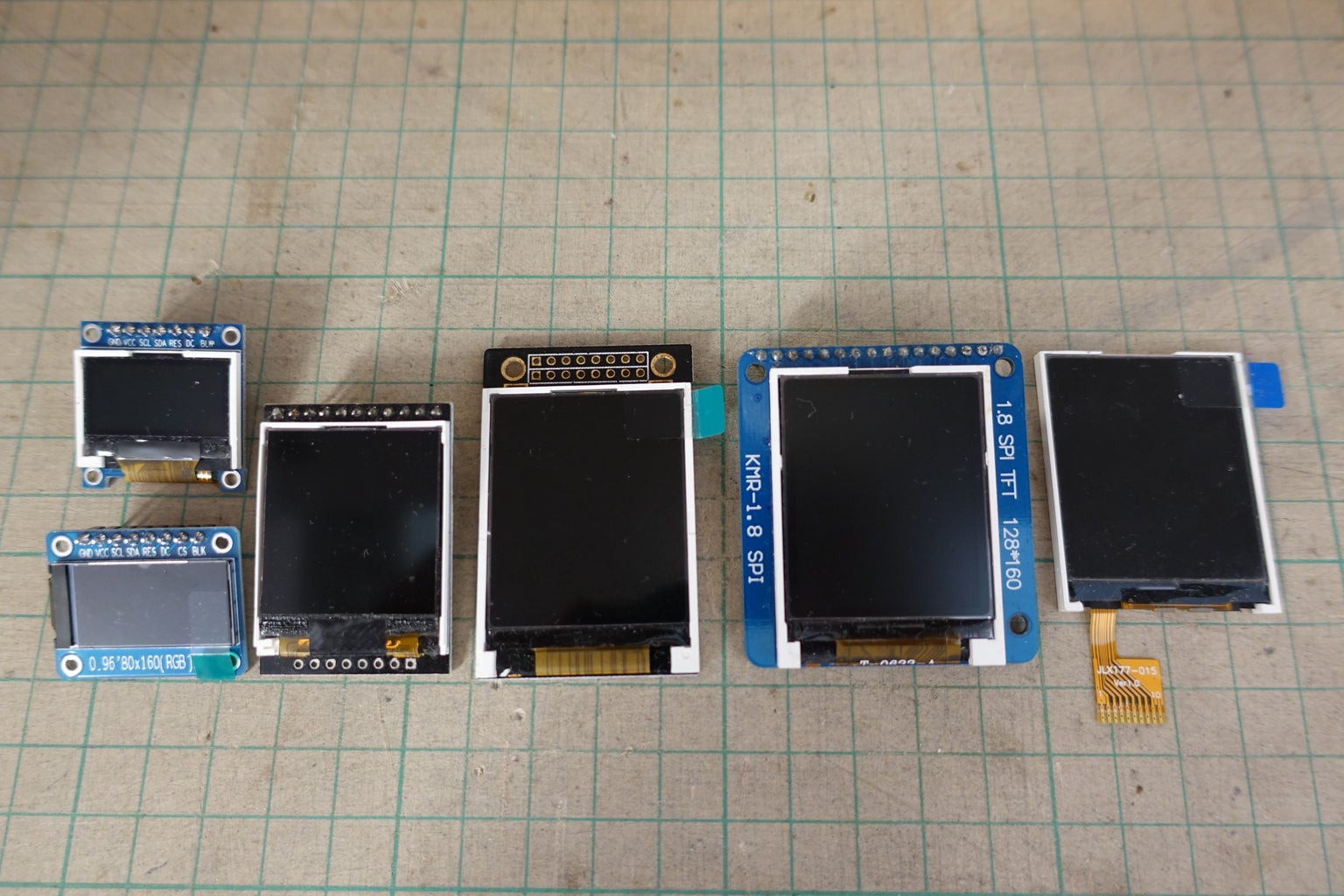

ST7735 is a very popular LCD driver model for the resolution 128x128 and 128x160. It may cause by its popularity, there are many manufacturer produce compatible product. However, they are not fully compatible.
The initial code have some variation, the color order can be RGB or BGR and the y coordinate range also have a few pixels variation. Some library differential it by red, green or black tag but the tag color may not always help. The worst case is alter the tag option one by one until you can see a fine result. The above last picture is an example of using wrong tag option, you can find 3 pixels height noise bar on the top.
Step 9: IPS LCD ST7735 80x160


Thanks for the popularity of wearable gadget, I can find more small size IPS LCD in the market this year(2018). The above picture is an 0.96" 80x160 IPS color LCD using ST7735 driver chip. As you can see in the 3rd picture, you can treat it as a 128x160 color display in code but only the middle part is actually displaying. The 4th picture is the display without breakout board, it is thin, tiny and very fit for a wearable project!
Note:
All IPS LCD have a common feature, the colors displaying are inverted, most driver chip like ST7735 can simply fix it by sending an invert command.
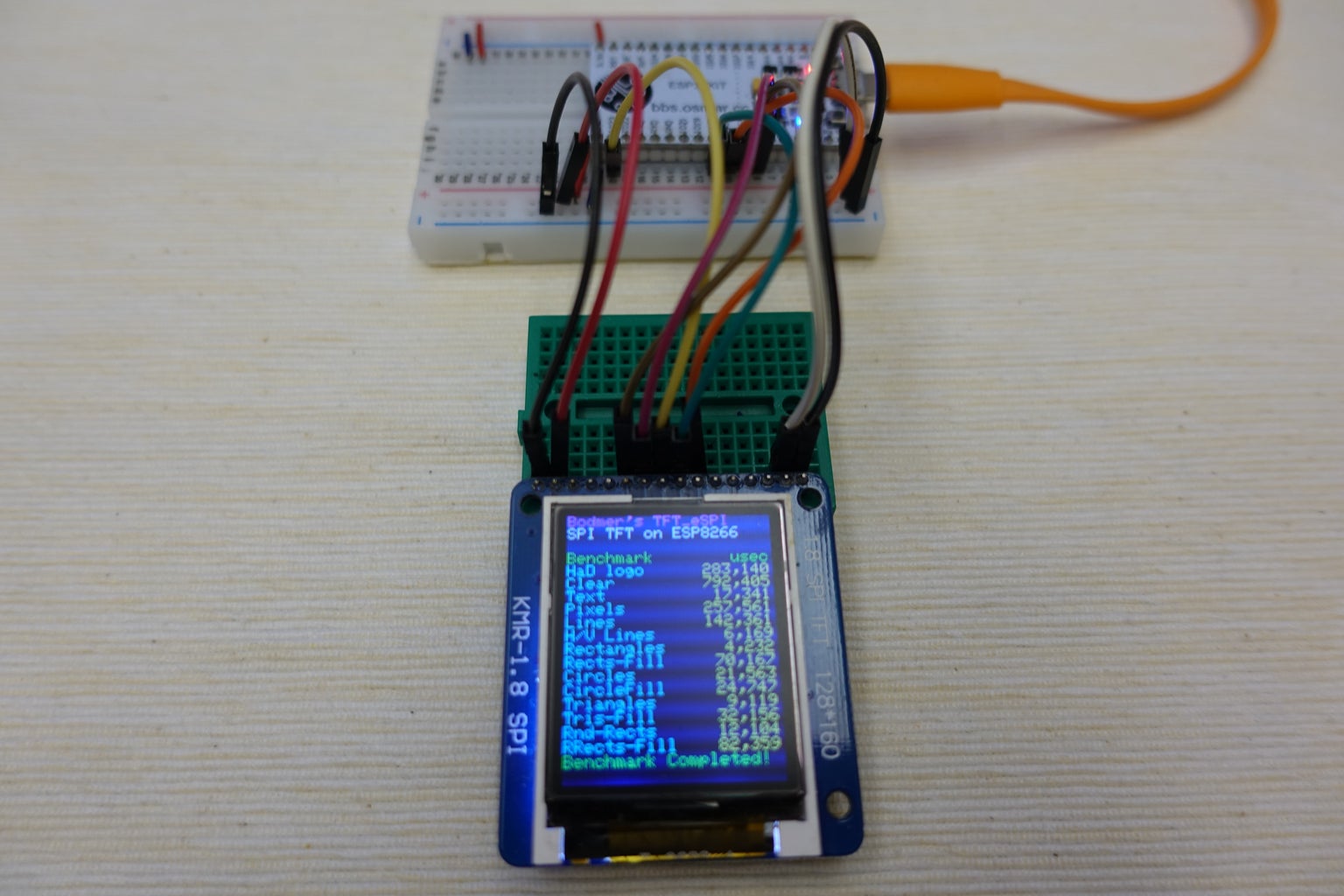
Step 10: IPS LCD ST7735 128x64


ST7735 still have another odd size color display, 0.96" 128x64. The resolution and form factor seems aim to replace 0.96" mono OLED SSD1306.
Step 11: Semi-permeable Trans-LCD SSD1283A
Semi-permeable Trans-LCD is a special display that still readable even backlight off or under the SUN.
SSD1283A is 1.6" 130x130 display, it claim only consume 0.1 in sleep mode and backlight turned off. In sleep mode the last drawn screen still readable under sufficient lighting.
Ref.:
Step 12: LCD ILI9225


It is a 2.2" 176x220 color LCD. It is relatively fewer projects using this chips and resolution. It may caused by the success of its chip family brother, ILI9341 (0.2" larger in size but have near double resolution).
Lower resolution still have its advantages, e.g. it can save half of the processing power on decoding the full screen size JPEG image and double the FPS ;>
Here are my project(s) using this display:
Step 13: IPS Round LCD GC9A01

This is another display since popularity of wearable gadget. You can treat it as a 240x240 display but without four corners.
Note:
This display is not 5V I/O tolerant. If you are using a 5V dev board like Arduino Nano, every I/O line should insert a 2.2K resistor in the middle.
Step 14: LCD ILI9341


I think ILI9341 is the most popular LCD driver chip in the hobby electronics market. In most case it is 240x320 resolution and have many screen size from 1.7" to 3.5". Some breakout board also built-in touch screen feature.
You can find many projects in GitHub using this. If you are designing to buy your first LCD, a ILI9341 breakout board is a good choice.
It is also easy to find a plain LCD without breakout board in the market.
Note:
This display is not 5V I/O tolerant. If you are using a 5V dev board like Arduino Nano, every I/O line should insert a 2.2K resistor in the middle.
Here are some project I am using ILI9341:
https://www.instructables.com/id/Connect-LCD-to-Ra...
https://www.instructables.com/id/ESP8266-WiFi-Anal...
https://www.instructables.com/id/Breadboard-RetroP...
https://www.instructables.com/id/Portable-WiFi-Ana...
https://www.instructables.com/id/ESP32-Photo-Clock...
Step 15: IPS LCD ILI9341


This is a IPS version of 2.4" LCD using ILI9341 driver chip.
The display result is very good but the vendor not provide a breakout board option, so you need wire it yourself.
Step 16: LCD HX8347C
It is a 2.8" 240x320 color LCD. The vendor not provide a breakout board option, so you need wire it yourself.
Step 17: LTPS TFT JBT6K71
It is a 2.4" 240x320 color LCD. This display only provide 8-bit parallel interface and cannot driver with SPI.
Step 18: IPS LCD ST7789
ST7789 also a common driver chip in ESP32 community. One of the reason is ESP32 official development kit using it. As same as ILI9341, ST7789 also can drive 240x320 resolution.
I have no 240x320 ST7789 display in hand, the above picture is a 1.3" 240x240 IPS color LCD.
This also the highest pixel density color display in my drawer. As same as normal LCD, it can direct operate in 3.3 V, so it is very good for making slim wearable device.
Step 19: IPS LCD ST7789 Rounded Corner
Step 20: IPS LCD ST7789 240x240


Step 21: IPS LCD ST7789 135x240
Step 22: IPS LCD HX8352C

This is a 3.0" 240x400 IPS color LCD. This is the only wide screen LCD in hobby electronics market I even seen.
Step 23: IPS LCD HX8357B
9-bit SPI
Step 24: LCD ILI9481
Step 25: LCD ILI9486


This is a 3.5" 320x480 color LCD. This resolution is a burden for normal MCU, it require over a second to fill full screen using Ucglib.
Step 26: LCD ILI9488
Step 27: IPS LCD R61529
Step 28: LCD ST7796 320x480
Step 29: Software Comparison

There are many display libraries that can support various hardware. I have picked 4 of most popular Arduino library for comparison:
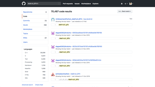
- Adafruit GFX Family
- TFT_eSPI
- UTFT-ESP
- Ucglib
The above picture is the hardware support list for each library.
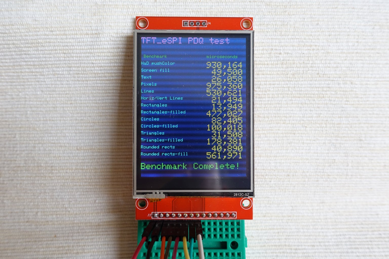
The display speed is one of the most important thing we consider to select which library. I have chosen TFT_eSPI PDQ test for this comparison. I have made some effort to rewrite the PDQ test that can run in 4 libraries. All test will run with the same 2.8" ILI9341 LCD.
For simplify the comparison process, all display use the same connection pattern.
Here are my connection summary:
ESP32               Display
Pin 5              -> CS (Some display not breakout this pin, simply skip it)
Pin 16             -> DC
Pin 17             -> Reset
Pin 18 (VSPI CLK)  -> CLK
Pin 23 (VSPI MOSI) -> MOSI (Some display call it Din)
You may find the code at Github:
https://github.com/moononournation/Arduino_graphic...
Update
As I found TFT_eSPI is the most potential display library for ESP32 in this instructables, I have paid some effort to add support for all my display in hand. The newly added display support marked letter M in red at the above picture, here is my enhanced version:
Step 30: Adafruit GFX Family


Adafruit sell various display module in hobby electronics market and they also have very good support in software level. Their display libraries all built on a parent class called Adafruit_GFX, so I call it Adafruit GFX Family. This library generally support most Arduino hardware (also ESP32).
In Arduino Library Manager simply search "adafruit display", you can see all the family members. If you want to install it, say ILI9341, simply select "Adafruit ILI9341" and then click install. Remember also install its dependent library "Adafruit GFX Library".
Step 31: TFT-eSPI

This library method signature is very similar to Adafruit GFX, but it is tailor-made for ESP8266 or ESP32. I think the source code is optimised for ESP32, so the PDQ result is much faster than other libraries.
You can install it at Arduino Library Manager by searching "TFT-eSPI" and then click install.
Note: The most difficult part using this library is you are required to configure this library before you can use it. The configuration file is located at the library folder, it should be "Arduino/libraries/TFT_eSPI/User_setup.h" under you own documents folder. It have many comments help you to do that, please follow the comments step by step to finish the configuration. Here is my User_setup.h for ILI9341:
<p>#define ILI9341_DRIVER</p><p>#define TFT_CS   5  // Chip select control pin D8<br>#define TFT_DC   16  // Data Command control pin
#define TFT_RST  17  // Reset pin (could connect to NodeMCU RST, see next line)</p><p>#define LOAD_GLCD   // Font 1. Original Adafruit 8 pixel font needs ~1820 bytes in FLASH<br>#define LOAD_FONT2  // Font 2. Small 16 pixel high font, needs ~3534 bytes in FLASH, 96 characters
#define LOAD_FONT4  // Font 4. Medium 26 pixel high font, needs ~5848 bytes in FLASH, 96 characters
#define LOAD_FONT6  // Font 6. Large 48 pixel font, needs ~2666 bytes in FLASH, only characters 1234567890:-.apm
#define LOAD_FONT7  // Font 7. 7 segment 48 pixel font, needs ~2438 bytes in FLASH, only characters 1234567890:-.
#define LOAD_FONT8  // Font 8. Large 75 pixel font needs ~3256 bytes in FLASH, only characters 1234567890:-.
//#define LOAD_FONT8N // Font 8. Alternative to Font 8 above, slightly narrower, so 3 digits fit a 160 pixel TFT
#define LOAD_GFXFF  // FreeFonts. Include access to the 48 Adafruit_GFX free fonts FF1 to FF48 and custom fonts</p><p>#define SMOOTH_FONT</p><p>#define SPI_FREQUENCY  40000000 // Maximum to use SPIFFS</p>
Step 32: Ucglib


You can install it at Arduino Library Manager by searching "Ucglib" and then click install.
Step 33: UTFT-ESP

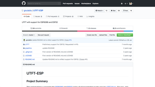

UTFT-ESP is based on the Rinky-Dink Electronics UTFT library and added ESP8266 and ESP32 support.
You can install it by download it at Github:
https://github.com/gnulabis/UTFT-ESP
And then copy the "UTFT" folder to the Arduino library folder.
Step 34: Fine Tune SPI Frequency


ESP32 + ILI9341 can run at SPI speed 40 MHz, it require some code change at library folder. The above pictures are the fine tuned result. Here are the code change summary:
Adafruit_ILI9341
This library has already defined SPI_DEFAULT_FREQ as 40000000 for ESP32 boards. You can also change the frequency while init:
tft.begin(80000000);
TFT_eSPI
User_Setup.h
// #define SPI_FREQUENCY 27000000<br>// Actually sets it to 26.67MHz = 80/3<br>#define SPI_FREQUENCY 40000000 // Maximum to use SPIFFS
Ucglib
src/clib/ucg_dev_ic_ili9341.c
ucg_int_t ucg_dev_ic_ili9341_18(ucg_t *ucg, ucg_int_t msg, void *data)<br>{
  switch(msg)
  {
    case UCG_MSG_DEV_POWER_UP:
      /* setup com interface and provide information on the clock speed */
      /* of the serial and parallel interface. Values are nanoseconds. */
      // return ucg_com_PowerUp(ucg, 100, 66);
      return ucg_com_PowerUp(ucg, 25, 66);
UTFT-ESP
hardware/esp/HW_ESP.h
// *** Hardwarespecific functions ***<br>void UTFT::_hw_special_init (  ) {
    if ( hwSPI ) {
        SPI.begin (  );
        // SPI.setClockDivider ( SPI_CLOCK_DIV4 );
        SPI.setFrequency(40000000);
Step 35: Comparison Round Up


Hardware
ST7735 and ILI9341 are the most popular display, this 2 are better option for the beginner. You may notice LCD have a big weakness, the viewable angle, some color lost outside the viewable angle and the screen become unreadable. If you have enough budget, OLED or IPS LCD have much better viewable angle.
Software
Speed
TFT_eSPI has best performance and Adafruit the second.
Popularity
In most case, we study how to use a code library by searching sample on the web. I have tried search four libraries keyword in Github, Adafruit is most popular and UTFT the second.
Diffcuilities
Only Adafruit GFX Family is fully configurable in user code level, other 3 libraries require some configuration in the library folder. And also Adafruit have very good portal, there are many detailed post teach you how to use their products.
Round Up
ILI9341 should be most valuable display for the beginner. Adafruit GFX Library should be most easy to use for the beginner, and since TFT_eSPI have very similar method signature, it is very easy to switch to a faster library later on.
Step 36: Optional Reading: Connect LCD Without Break Out Board


OLED require 14 V to light up the pixel so it is not easy to decouple the breakout board. On the other hand, LCD (also IPS LCD) usually operate in 3.3 V, as same as the ESP32. In most case, there are only the LED control circuit required between LCD and ESP32, i.e. a transistor and few resistors. So it relatively easy to make it.
It is very important to read the data sheet first before you decide not using breakout board. The pins layout, pin pitch size, the sample circuit connection and maximum rating all you can find in data sheet. The maximum voltage is especially important, you should sticky follow the rating or you will blow your LCD. The chip can operate in 3.3 V but LED may be 2.8 - 3.0 V so it require some electronics in the middle, most data sheet have the sample circuit. You may ask your seller send a soft copy of data sheet to you or simply Google it by the model number.
My special hint: I like to soldering a FPC cable with the same pin pitch size as the LCD to help the connection with the MCU. I have used this technique in these instructables:
Step 37: Optional Reading: Color Depth
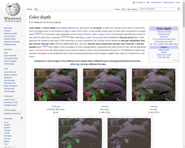
If you read through the data sheet of the color display, you may find most of color display can support 18 bit color depth (6 bit for each RGB channel). 18 bit color depth can have a better image quality that 16 bit color depth (5 bit in red and blue channel, 6 bit for green channel). However, only Ucglib actually run at 18 bit color depth (262,144 colors), other 3 libraries all run at 16 bit color depth (65,536 colors). It is because 18 bit color depth actually require transfer 3 bytes (24 bit) of data for each pixel, it means 50% more data require to transfer and store in memory. It is one of the reason why Ucglib run slower, but it can have a better image quality.


![Tim's Mechanical Spider Leg [LU9685-20CU]](https://content.instructables.com/FFB/5R4I/LVKZ6G6R/FFB5R4ILVKZ6G6R.png?auto=webp&crop=1.2%3A1&frame=1&width=306)


