

Introduction: Sew a Circuit


When building wearable electronics, you do not need to stick with wires when creating the pathways through which electricity will flow (traces). Conductive thread and fabrics can be used to make the circuits soft and flexible. In this lesson, you will be introduced to sewing with conductive thread by creating your first soft circuit!
You will sew the circuit you built in the previous lesson onto a piece of fabric. I have included a robot design for you to follow or you can design your circuits shape. When done, the circuit can be sewn onto a favorite jacket as a patch or worn as a pin (I will show you how!).
Let's get started!
You will learn:
+ the running stitch
+ how to work with conductive thread
+ what a short circuit is
Step 1: Materials

+ conductive thread
+ sewing needle
+ 5" x 5" piece of felt
+ 5" x 5" piece of felt in contrast color (optional)
+ safety pin (optional)
+ fabric marker (optional)
+ fabric glue
Circuit from Intro to Electricity lesson:
+ 5mm LED
+ 3V coin cell battery
+ resistor
Step 2: Short Circuits + Poor Connections

Before we begin, let's go over some good practices when using conductive thread. When creating wearable electronics, the number one thing that causes a circuit to not work is a short circuit.
What is a short circuit?
A short circuit is the failure of electricity to flow properly in a circuit because a connection is accidentally made between two points. Current flows down the path of least resistance. If this connection has a lower resistance than the intended path, the current will take it, creating a short.
A circuit sewn with conductive thread is prone to short circuits because of the hairy nature of the thread. Short circuits can also be accidentally made when a trace continues to the next trace, bypassing a component, instead of being knotted and cut. By knowing what short circuits look like, you can avoid them, but sometimes a thread becomes loose and touches a part of the circuit nearby. For hard to see shorts, you will learn how to test for short circuits later in this lesson.
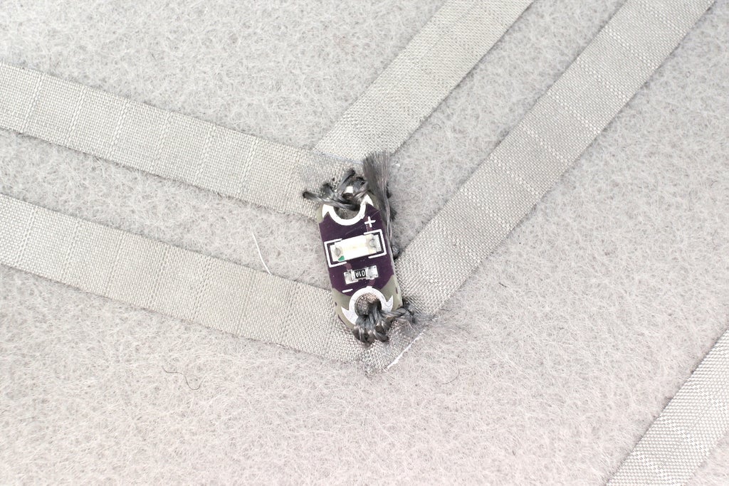
Incorrect - A loose end of conductive thread is coming from the bottom (ground/-) and is touching the top (power/+). The current will not pass through the LED. Instead, it will take the path of lower resistance through the conductive thread.
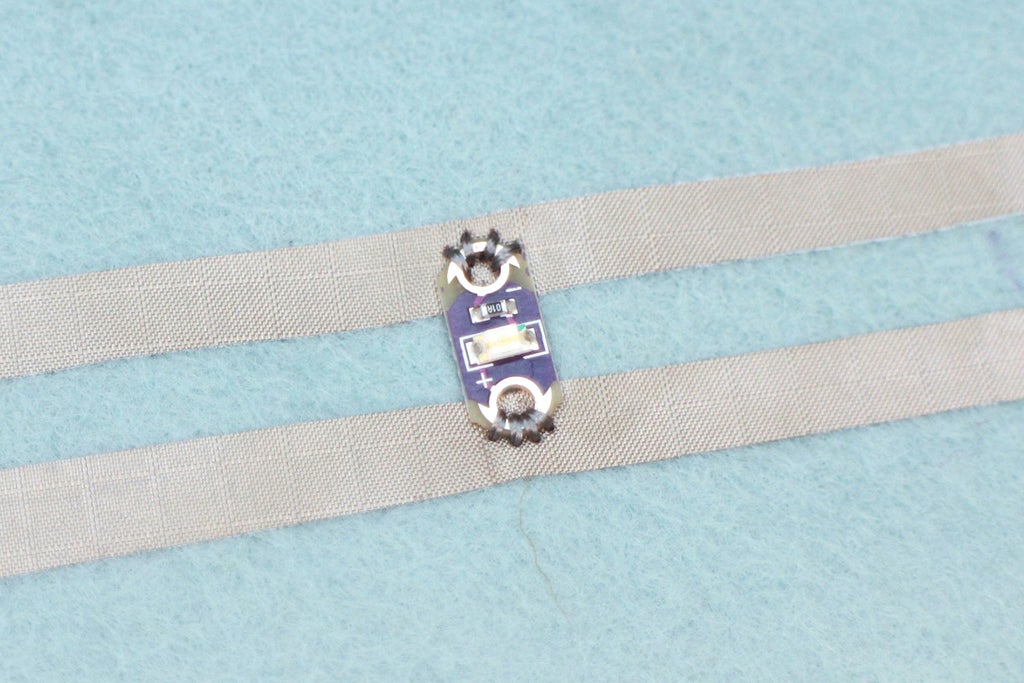
Correct - This is an LED with no short circuit occurring between power (+) and ground (-).

Incorrect - A short created by forgetting to end one trace and begin a new one. This continuing stitch line connects two sides of a component together. The current will not pass through the component. Instead, it will take the path of lower resistance through the conductive thread.

Correct - One trace ends and another separate trace begins on the opposite side of a component. The current will then pass through the component instead of taking a shortcut on the path of lower resistance.
Poor Electrical Connections
The second thing that usually gets beginners is making a poor connection. This is done by sewing a connection that is loopy and loose. A loose connection can disconnect as the fabric and components move around breaking the flow of electricity. Stitches need to be kept small and tight. Make several stitches through a component and the fabric to make a strong electrical connection.

Incorrect - Loopy and loose connection and trace stitches. This connection will sporadically break while the circuit is moved around.

Correct - Tight and small stitches make good connections and a neat stitch line.
Step 3: Introducing Conductive Thread

Conductive thread is commonly made from stainless steel or nylon thread plated with silver. Just like any thread, it is be made of many tiny strands that are twisted and wound on a spool. Besides being soft and flexible, there are a couple important ways that conductive thread differs from wire. Let's go through those now.
Insulation
Wire comes with a coating to insulate it from electronic waves that may interfere with the circuit. More importantly, the coating also prevents any physical contact with the metal wire itself, which stops short circuits from happening. Conductive thread does not have a coating. So when used, a step of insulation can be added to the process to protect the exposed thread.
Resistance
Copper wire that is typically used in electronic projects has very a low resistance value. For example, a length of copper that equals 10 feet will have a resistance less than 7 ohms. Remember, Ohms is the measuring unit of resistance and resistance is the act of resisting current. In fact, the resistance is so low in copper wire that it is thought of as highly conductive. Conductivity is the allowance of current flow.
Conductive thread, on the other hand, has a higher resistance so you need to consider it when building a circuit. For example, it can resist up to 14 ohms per foot, this would calculate to 140 ohms for that same 10-foot length. If you have an LED at the end of that 10 feet and your battery at the opposite end, that LED may be dimmer than expected because the thread acts like a resistor taking some of the current and voltage from the LED.
To sum up, a wire is highly conductive because it does not resist any current, which is typical when building circuits. With conductive thread, you do need to take it into account it's level of resistance, especially if you are using significant lengths of it to build your circuit with. Use your multimeter to measure long lengths of conductive thread to see how many Ohms one foot is or how many Ohms two feet.
Adding Thread's Resistance to the Circuit
The fact that conductive thread resists current does not have to be a negative thing. To turn it into a positive, team the value of resistance from the thread up with the resistor to protect the LED.
For example, the circuit you are building uses very short distances of conductive thread, so the ohms will be around an additional 3 - 5 Ohm. Use your multimeter to measure them!
If we add this to the 47 Ohm resistor in the example circuit the total comes to 50 - 52 Ohms. So, knowing that the thread can make up for some resistance the 47 Ohm resistor now sounds like a better choice than 100 Ohms (the alternative choice from the resistor kit). To be honest, these differences are a bit nit-picky for this circuit. Still, it's important to start thinking about how the resistance of conductive thread can affect your circuit!
Step 4: Prepping Components

It's time to take a look at your circuit and it's components again. Take them off the alligator leads, you will be sewing them all down to a piece of fabric and replacing the alligator leads with conductive thread.
The battery holder has two small holes to sew through, but if you look at the LED and resistor, you will notice that there isn't any easy way to sew them down. Luckily, these components are through-hole components, meaning they have long metal leads that are meant to go through the holes of a circuit board. These kinds of components can easily be made sewable.
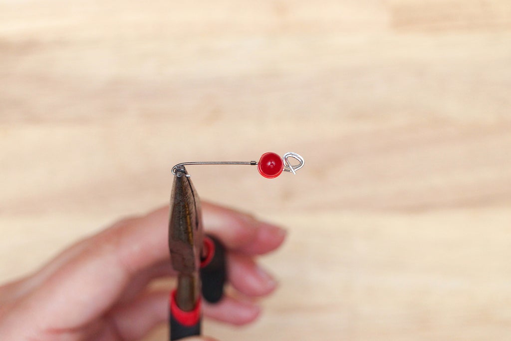
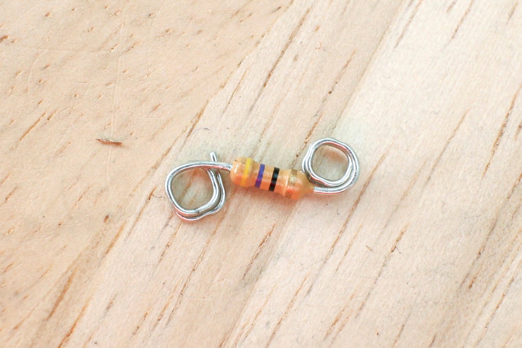
To make a through-hole component sewable, grab a pair of needle-nose pliers and curl each leg up to make a circle. The components now have holes that can be used to stitch around with conductive thread, securing them to fabric and making electrical connections.

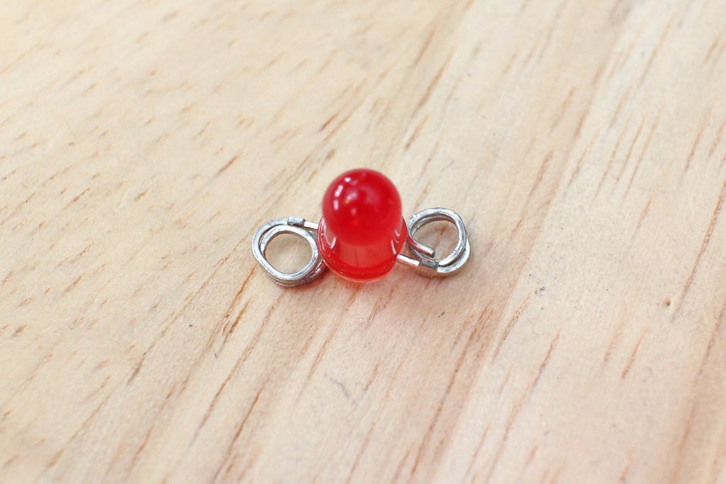
Now that the legs are curled up on the LED, how can you tell which one is the cathode (negative/-) and which one is the anode (positive/+)?
There are two other ways to find out:
1) Look closely at the dome, can you see a flat spot on the side of the lens? This is the negative side!
2) Look inside the lens where the leads extend up. One side is much larger than the other, this is called the anvil and is connected to the negative lead.

Step 5: Place Components


Use the attached robot design as a reference or create your own design as you go.
Place the LED, resistor and battery holder where you want them to be. The only thing you have to make sure of is that they create a closed circuit, causing the current to run through each component. Here is the circuit diagram for reference.

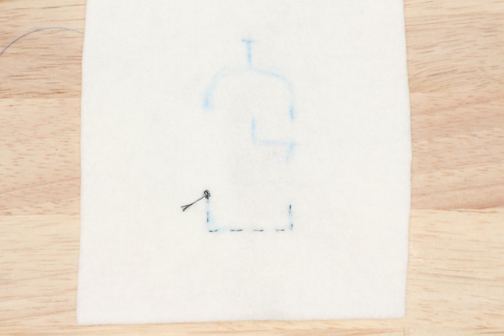
Step 6: Draw Traces

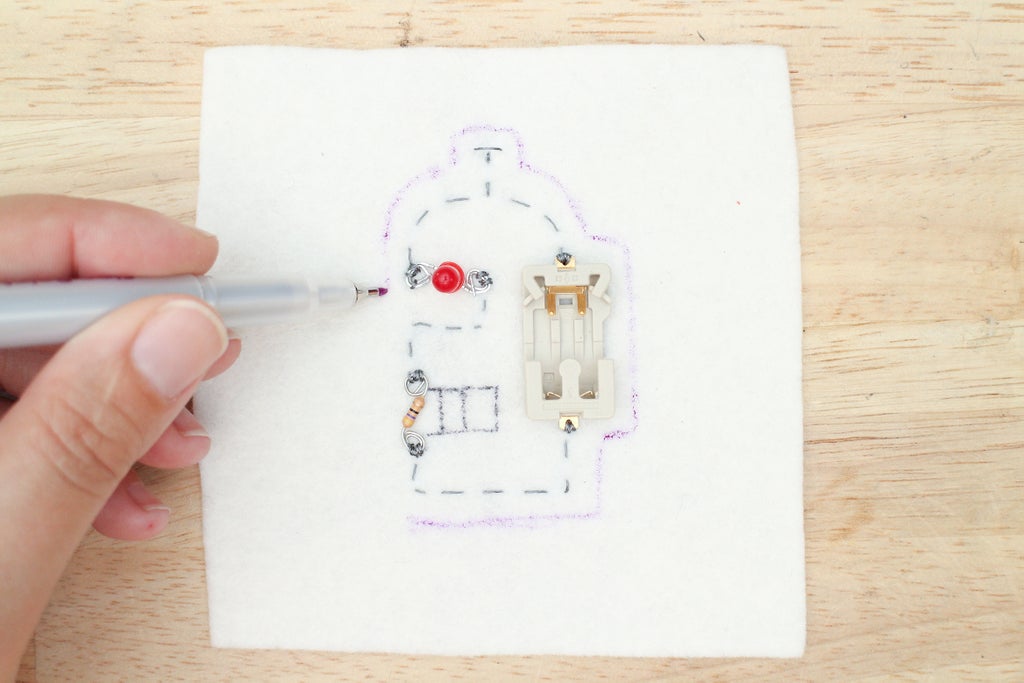
Decide which side of the fabric you want to face out, this is known as the right side of the fabric. Once you know, turn the fabric over. You will be drawing on this side to keep the right side clean and looking it's best. Keep in mind that your finished design will be mirrored once turned over.
Grab a fabric marker or some chalk and drawn in your traces, making these connections.
battery power (+) --> LED power (+)
LED ground (-) --> leg of resistor (your choice because it's not polarized)
leg of resistor --> battery ground (-)

Step 7: Sew Down Battery Holder

Knowing how to sew down components using conductive thread can make or break a circuit. As mentioned in a previous step, it's all about a good electrical connection. Connections in traditional circuits are usually made by soldering components together. When making soft circuits you use conductive thread to stitch connections together.
Knot an 18" length of conductive thread and thread a needle. Push the needle through the wrong side of the fabric to the right side and through the positive (+) tab of the battery holder. To identify power look for the plus (+) sign on the battery holder.
Make a small stitch over the metal tab and back through the fabric. Pull the stitch tight. Repeat until you can not push the needle through the hole anymore, which should be at least 3 times. 
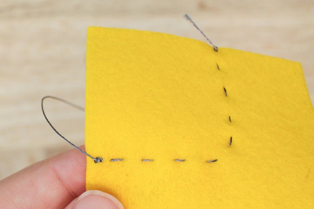
Step 8: The Running Stitch

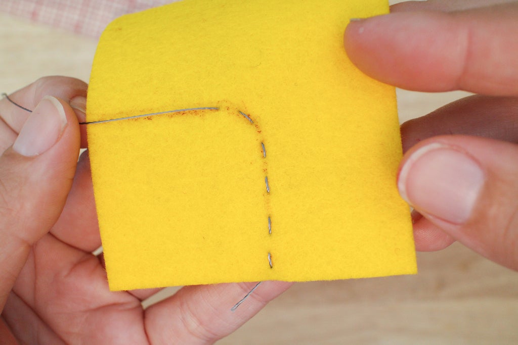
This stitch is THE basic stitch of hand sewing and embroidery and is the one you use to sew this lesson's project. It's made by weaving the needle in and out of the fabric, creating a dashed line with equal parts.
This can be done by poking through the fabric and pulling the thread tight for each stitch or use the length of the needle to create multiple stitches at once.


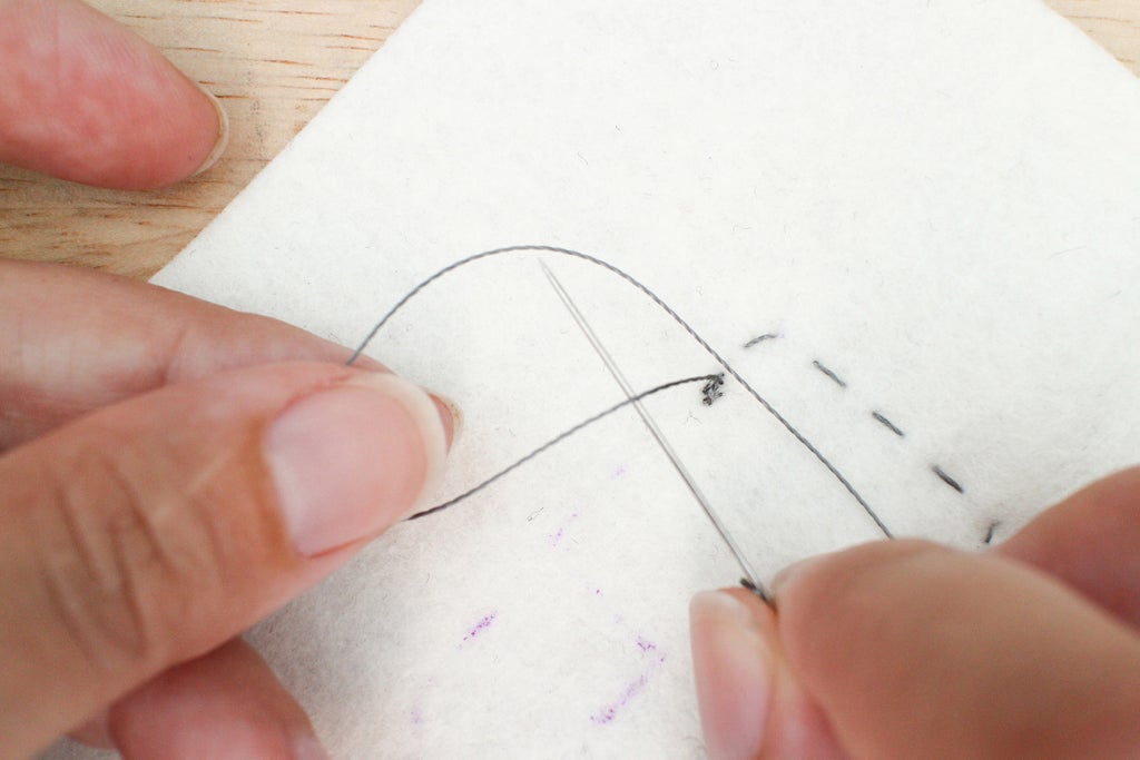
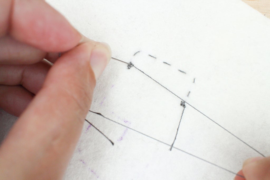
Step 9: Ending With a Knot
When working with conductive thread, or any thread for that matter, you will need to finish a stitch line with a knot. When finishing with a knot it can be tricky to knot close to the fabric. Luckily, there is something that you can use that is already within grasp - a sewing needle.
When you have reached the end of a stitch line, create a loop with the thread and slide the needle through the loop.

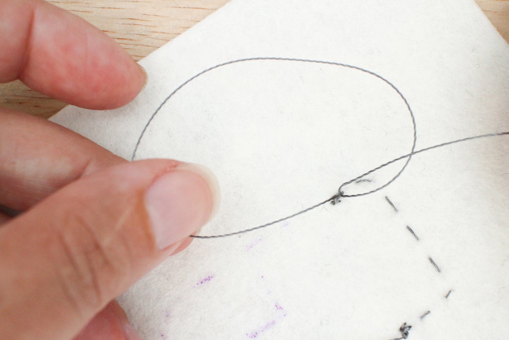
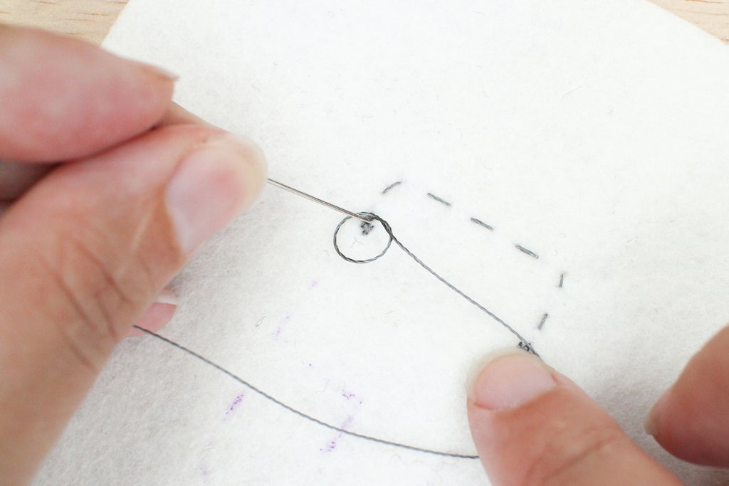
Pull the thread and guide the knot with your hand down towards the fabric, leaving a small loop. Place the point of the needle in the middle of the loop and tighten the knot around it. The knot will slide down the needle and towards the fabric. You can help it along with your fingers while the needle is still in the middle and when you have removed it. Pull tight.


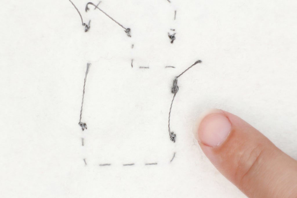
Step 10: Sew and Knot First Trace

After you sew the positive (+) side of the battery down, turn the felt over so you are working on the back. Continue to sew using the running stitch along your drawn line until you get to where the resistor goes.
End the stitch line so the needle ends up on the right side of the fabric. Thread the needle through a hole of the resistor. Since the resistor is not polarized it does not matter which side you choose to thread through. Stitch it down using the same method with which you sewed the battery holder with, using small and tight stitches. Knot and cut the thread on the back of the fabric. Your first trace is done! Knot another piece of conductive thread, and you are ready to sew the next one.

Step 11: Finish Sewing the Circuit

Continue to sew the second trace, resistor to LED and so on using the skills learned so far. Use the list of connections and your drawn traces to guide you.
A couple important things to keep in mind as you finish the circuit:
1) The LED is polarized, meaning it can only go in one way for it to light up. For a refresher, go back to the Introduction to Electricity lesson to find out how to tell which side goes towards ground (-) and which goes towards power (+).
2) Each trace is separate from the other. Knot and cut each stitch line once you have connected two components.
Step 12: Glue Knots

Stainless steel thread can be springy and holds some tension, so a knot may want to come undone. To solve this, we will secure each knot with fabric glue. Turn the fabric swatch over and check out all the long tails from finishing each trace. Tighten any knots up that look loose and put some Aleene's glue on each knot.

Step 13: Cut Off Tails

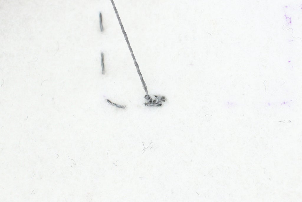
All the long tails from finishing need to be cut off or they could reach over and touch another trace or component creating one of those dreaded short circuits I have talked about.
This tail is creating a short that will bypass the resistor.

The tail has been moved so it is no longer creating a short by touching the other side of the resistor.
Once the glue is dry, cut all the tails off as close to the knot as possible.

Step 14: Test Your Circuit With a Multimeter

Time to grab the multimeter again! In the previous Introduction to Electricity lesson you learned how to read resistance and voltage. Now, let's learn how to test for good connections and short circuits. This is the reason you will you reach for your multimeter 90% of the time when creating wearable electronics.
Turn the dial on the multimeter from Off to what looks like a sound wave symbol. This puts the multimeter on the continuity setting. Next to the sound wave there may also be a the schematic symbol of a diode.
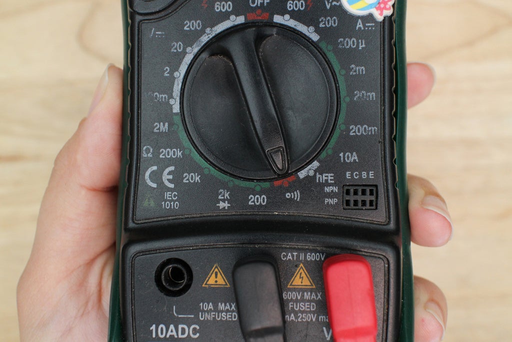
Multimeter on continuity setting.
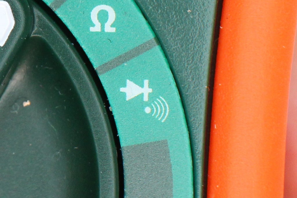
The sound wave symbol next to the schematic symbol of a diode. This is also the continuity setting and diode test setting.
There are three things you are going to test for now that your multimeter is on the continuity setting.
1) good connections
2) short circuits
3) LED is sewn in the correct way and working correctly
Touch the black and red probes together and listen for a beep. When the multimeter beeps this means a small amount of current is flowing from one probe to the next creating a closed circuit. The important thing to know while on this setting is where to place your probes. Knowing how to place the probes will tell so you whether that beep is a good thing (good connection) or a bad thing (short circuit).
Good Connections
After you sew an electrical connection with conductive thread you want to check it to see how you did. To do this, place the sewn connection between the two probes. Do not touch the sewn stitches themselves, put one probe on the lead of one item and the other probe on the stitched line. If the sewn connection between the two probes is a good electrical connection, the current will flow through it causing the multimeter to beep. If it's a poor and loosely sewn connection it will not beep. Or it may give quick beeps when moved around. If this is the case, you will want to sew over that connection again or completely redo it.
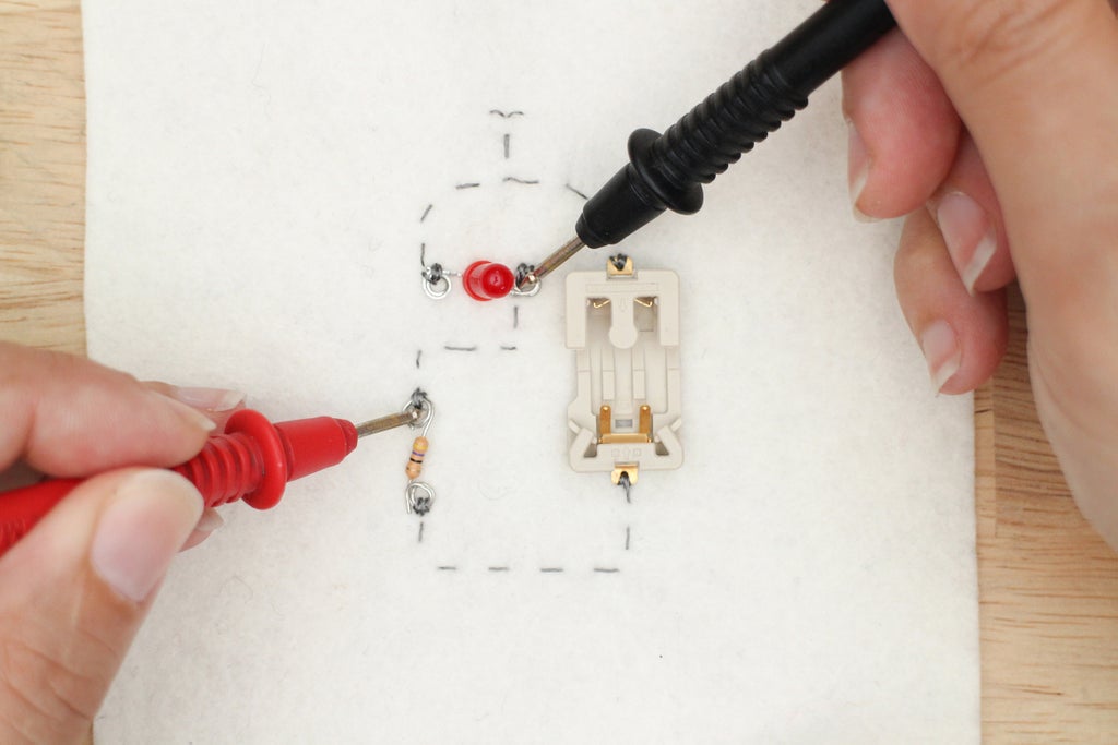
Testing the electrical connection between the LED and the resistor. Multimeter will beep, which is good!

Testing hand-sewn connection by placing it between probes
Short Circuits
When testing for short circuits you can put the two probes anywhere you think there may be potential for one. Remember that the current flows between the two probes and if there is an electrical connection between the probes the multimeter beeps. If there is no electrical connection it stays silent. When testing for shorts you want it to stay silent. Place any area you think may have a short between the two probes. Potential places to check for shorts:
+ the area between two traces that look very close to one another
+ across a component, like an LED or resistor
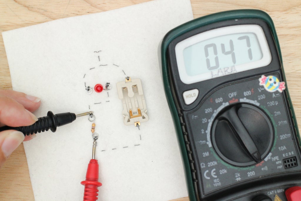
Testing for a short across the resistor. The multimeter will be silent, which is good! A number, however, will pop up on the screen. On this setting, it displays the resistance if above a certain value. It reads 47 because my resistor is 47 Ohms. That's correct!

Testing for a short between the battery, the multimeter stays silent which means no short!
Testing an LED
The continuity setting on your multimeter is also the diode test setting. You can test your light emitting diode by placing the red (power/+) probe on the power (+) lead and the black (ground/-) probe on the ground (-) lead of the LED. You will see the LED glow faintly from the current running through the LED from one probe to the next. This tells you the LED is working correctly.
What about testing the polarity? Look to see if the red probe is on the side that is connected to the power (+) of the battery. If it is that's good! This means that your black probe is on the ground (-) side of the battery and your LED is sewn in the correct direction!
Below you can't see it but the LED is glowing faintly. The black probe is on the side that is connected to the ground (-) tab of the battery and the red is on the side that is connected to the power (+) tab. This is correct!

Step 15: Add Details

At this point, the circuit is sewn, the knots are glued and the connections are tested.
This step is optional and will only apply to you if you are using the robot design or if you created your own design that calls for more detail.
Grab a fabric marker and draw in the mouth or any other detail you would like to add.
* Afterwards, I realized how much this circuit design looked like Bender from Futurama! Which doesn't surprise me since I'm a huge fan!
Step 16: Power Up

Place the coin cell in the battery holder and watch the LED light up!
Troubleshooting:
The LED isn't lighting up.
+ Check to see if the LED is put in the right way, remember it's polarized, the current can only flow in one direction to light it up.
+ Look and test for short circuits.
The LED burnt out or the battery became hot.
+ Look and test for short circuits
Step 17: Make Into a Pin

The project works as a patch as is, or you can wear it as a pin. To create a pin, you will need a safety pin and another piece of felt to create a backing.
First, cut your design out and place it on the second piece of felt. This second piece acts as the pin's backing. Cut the design out again, you can cut close to the edge or leave a border.
Mark your cut line.
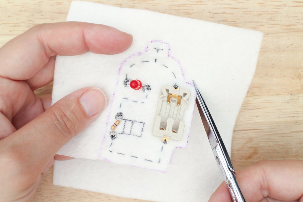
Cut design out.

Cut out backing.
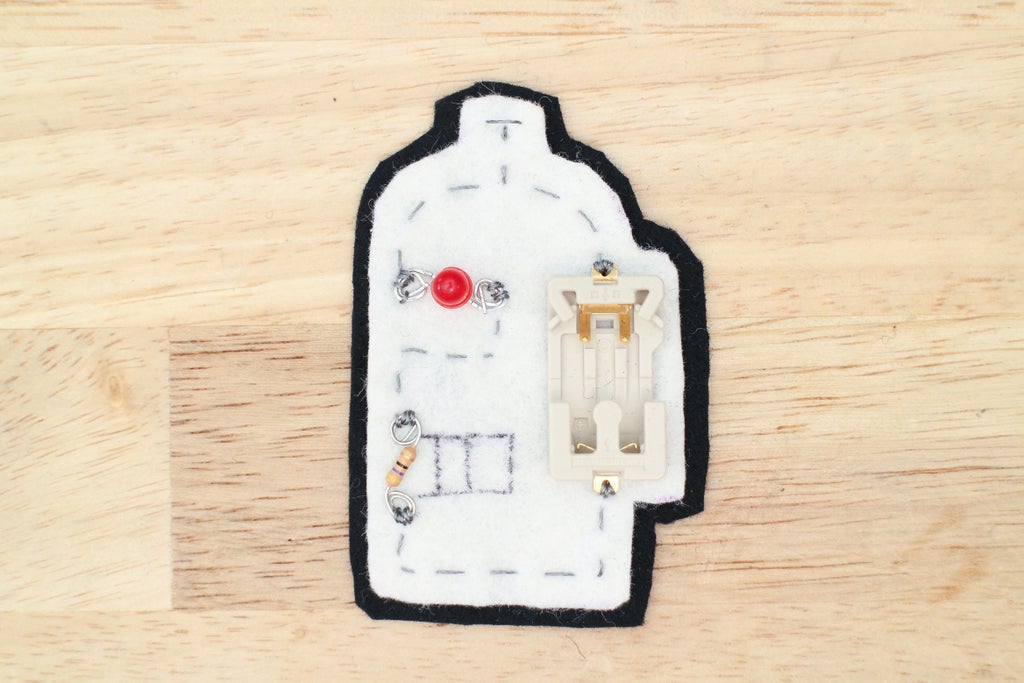
Backing with border.
Glue the circuit to the backing. You need to use a strong glue like Fabri-Tac for this step and the next.
Cut a small strip of felt about .75" x 2", this will secure the safety pin to the backing. Glue the strip over the safety pin positioning it where you want. It works best in the middle or at the top of the design.

Cut and apply Fabri-Tac.

Glue down, pressing firmly around the safety pin.
Step 18: Wear


The circuit can be worn with the battery in as a glowy accessory or without. I find it looks equally as good without the battery.
Step 19: Test Your Knowledge
{
    "id": "quiz-1",
    "question": "What is a short circuit?",
    "answers": [
        {
            "title": "The redirection of electricity flow in a circuit from it's intended path.",
            "correct": true
        },
        {
            "title": "When a circuit is incomplete, preventing electricity to flow.",
            "correct": false
        }
    ],
    "correctNotice": "That's correct",
    "incorrectNotice": "That's incorrect"
}
{
    "id": "quiz-1",
    "question": "When one piece of conductive thread connects the power (+) and ground (-) of an LED it will light.",
    "answers": [
        {
            "title": "false",
            "correct": true
        },
        {
            "title": "true",
            "correct": false
        }
    ],
    "correctNotice": "That's correct",
    "incorrectNotice": "That's incorrect"
}
{
    "id": "quiz-1",
    "question": "You want the multimeter to beep while you are testing a hand-sewn electrical.
connection.",
    "answers": [
        {
            "title": "true",
            "correct": true
        },
        {
            "title": "false",
            "correct": false
        }
    ],
    "correctNotice": "That's correct",
    "incorrectNotice": "That's incorrect"
}
{
    "id": "quiz-1",
    "question": "You want the multimeter to beep when testing for short circuits.",
    "answers": [
        {
            "title": "true",
            "correct": false
        },
        {
            "title": "false",
            "correct": true
        }
    ],
    "correctNotice": "That's correct",
    "incorrectNotice": "That's incorrect"
}
Step 20:
Did you make a robot too? Or maybe you made a palm tree or questions mark. Show off your sewn circuit below!


![Tim's Mechanical Spider Leg [LU9685-20CU]](https://content.instructables.com/FFB/5R4I/LVKZ6G6R/FFB5R4ILVKZ6G6R.png?auto=webp&crop=1.2%3A1&frame=1&width=306)


