

Introduction: Stacked Collapsible Tree


Whatever you celebrate there's always a place for a festive tree, especially one that doesn't take up much room! This collapsible desktop tree is made from strips of stacked strips of painted wood, the strips can be rotated to create a 3D effect of a tree with a large canopy. There's a few was to create something like this, but I was challenged to use Tinkercad, a free browser-based CAD program for kids, and a laser cutter.
DISCLOSURE
Dremel was kind enough to loan me a laser to try out and see what projects I could come up with using Tinkercad. You can find out more about Dremel's new laser cutter and get a hefty discount here (discount ends September 30, 2018).
The process I used allows this tree to be scaled to almost any size.

Though you could make this by hand, making small and precise repetitive cuts is tough (and boring). Luckily there's a tool in Tinkercad that can help us manage the design very easily: Codeblocks. Using Codeblocks, design commands can be dragged around (instead of types) and uses the computer to design us the exact pieces we need. The neat thing about using Codeblocks is that this design can be changed easily to scale however you need.
The SVG file is available at the end of this step.
After Codeblocks generated the design I was able to export the files into a format that could be laser cut.
Ready? Let's make!
Attachments

Step 1: Codeblocks
Tinkercad has a new function called Codeblocks. This function is still in beta, so there will be more functionality being added in the coming months.
Tinkercad is a completely free web-based design program that's super easy to pick up. The Codeblocks function operates a lot like Scratch Coding, where there are simple modules that get dropped and dragged to preform a function. The added benefit of having this in the Tinkercad interface is that the command blocks will output a shape.
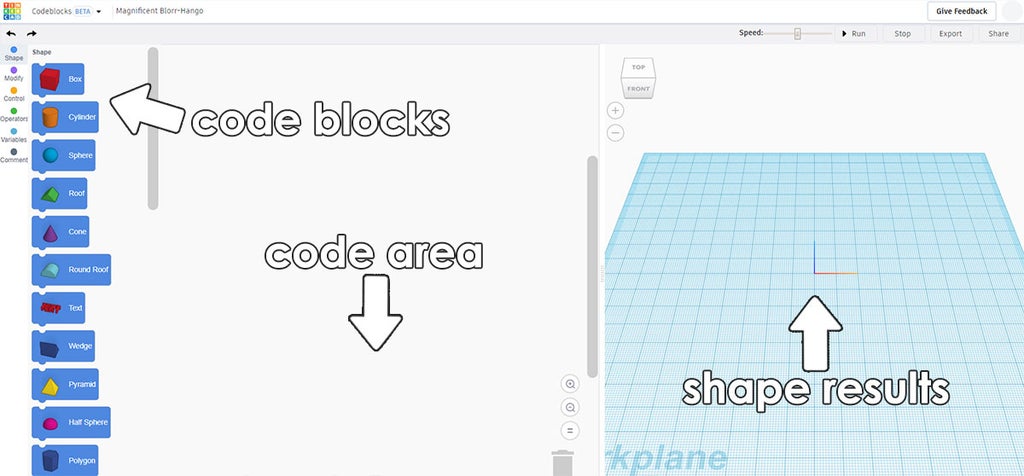
The bar on the left is a library of shapes and commands. These blocks can be dragged and rearranged in the code area in the middle of the screen. The Codeblocks can be played using the play button on the top right of the screen, with the results displayed on the right.
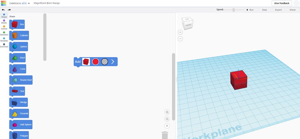
A simple example of a box draged from the library onto the code area results in a box dropped in the workplane on the right.
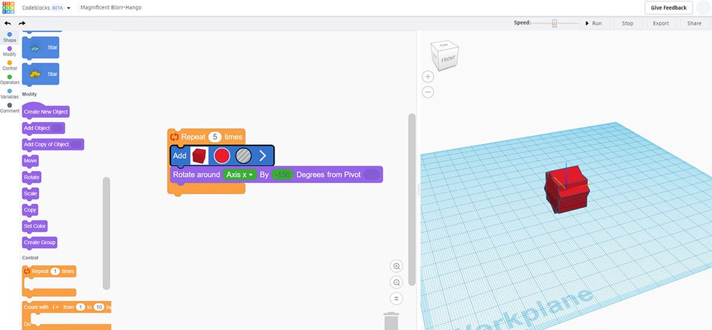
Along with shapes, the library also has a few other tricks. In the example below I had the box rotated around the X axis 5 times. This is only an example of what a section of Codeblocks could look like, and has nothing to do with the design of the collapsible tree I designed.
Now that we know some basics on how Codeblocks work, let's put that power to work for us in designing.
Step 2: Reference

Codeblocks can solve most of the design, but there's a reference dimension needed before any design is started.
The cut pieces will rotate a thin dowel, and that's the dimension we need to start. Using calipers the dowel diameter was measured. This is the number we'll design the tree around.
Step 3: Disgn With Codeblocks
Start a new Codeblocks design Then drag the box shape and a cylinder shape onto the design area. Inside the Codeblock for each there are some parameters to edit. I started with making the box 22 wide and 15 deep, making a long rectangle shape. Since we will be laser cutting there's no need to be specific about the height of the piece, so I put it at 2.
The cylinder will be used to make an opening in the rectangle shape. Using the reference measurement taken for the dowel I used, I put the diameter in the cylinder field and made the shape a hole instead of a solid.
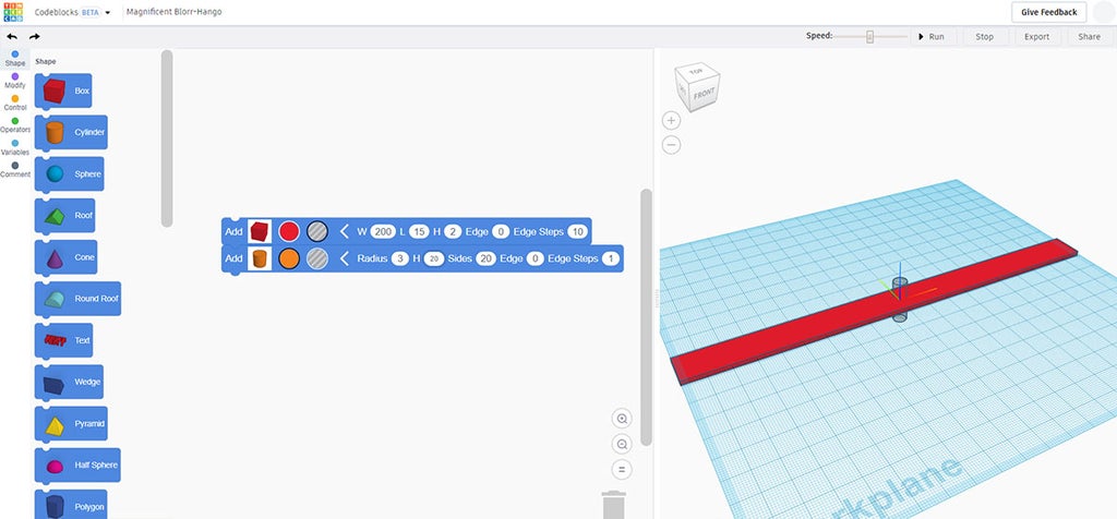
If we run the simulation now the blocks are laid on top of each other and look right for the design.
The aim is to make iterations of this one design, but shorter by a few millimeters each time, keeping the rest of the parameters the same. One option for this would be to drag in more shape blocks and entering in the values to ge progressively smaller, but that is not an efficient way to design.
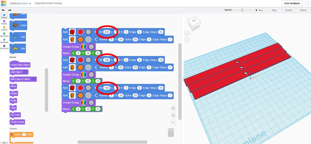
In the image above the initial shape was grouped together and then moved off the center, then a new shape was dropped in and repeated.
Instead, we'll use the power of Codeblocks to do the hard work for us.
Step 4: Start Coding
From our original box and cylinder design I added 2 modify blocks: create group, which groups the box and cylinder hole together, and move which moves the grouped shape out of the way so the next shape can be placed without overlapping (my rectangle is 15mm wide, so moving the piece 16mm leaves a gap of 1mm).
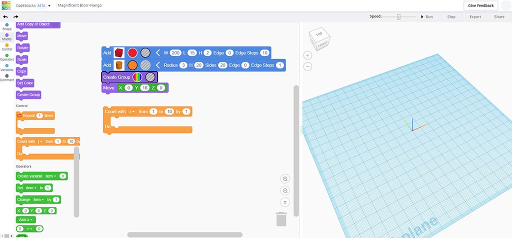
From the block library on the left, the orange Codeblocks are control blocks. When this block is dragged over shape commands it will perform a specific action (in our case, reducing the width) for a specified number of times.
Adding this over our existing blocks we can modify the command. Here's what it comes up as:
Count i from ___ to ___ by ___
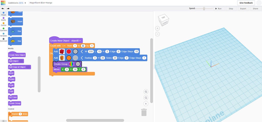
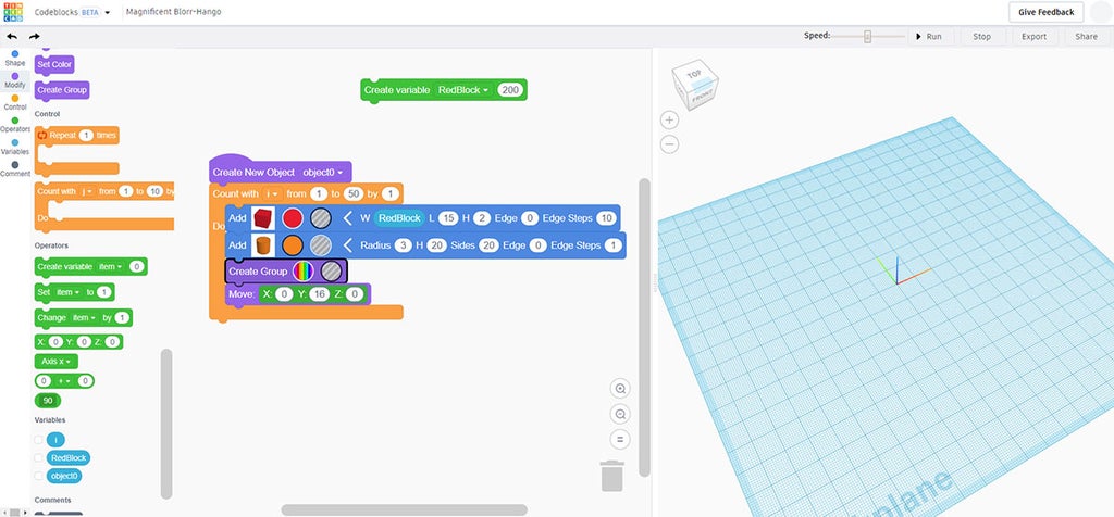
We'll define i as our original length, 200mm. To do that grab a green operator block and drag it onto the design area. This block doesn't need to be attached to anything, but the code will reference it. Set i to 200.
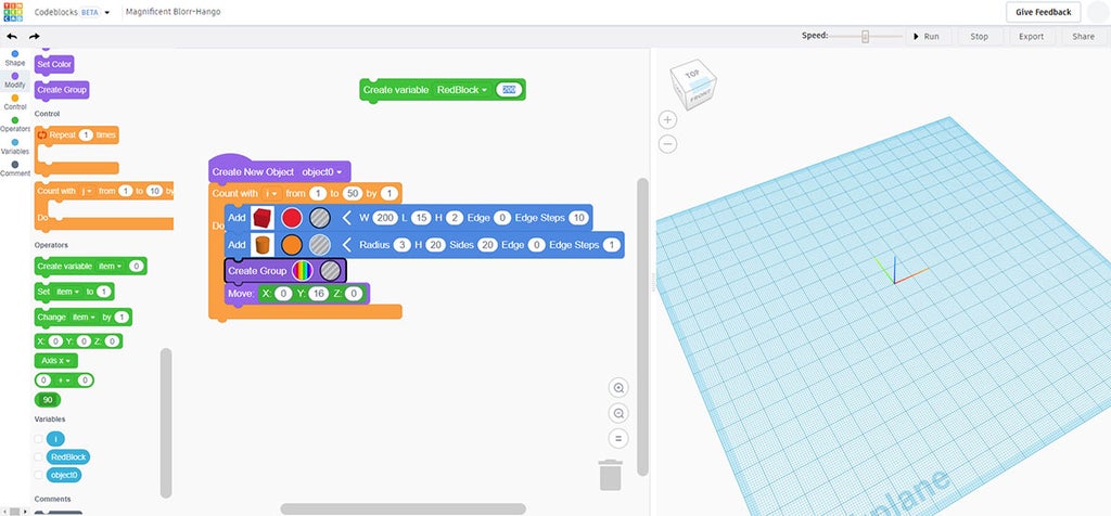
We want to go from 1 (our first piece) to 50 (total number of pieces), and it's stepping through each time by 1.
Step 5: Code + Export
Running the simulation now produces a series of identical versions of the rectangle. This is a good start, but we want the length value to decrease with every instance. For that we'll need another operator.
Sidebar: since Codeblocks is still in beta I ran into a problem with creating too many elements. To get around this I added in some custom operators to move the rectangle and cylinder pieces independently, which is why the code looks different in the image below from the previous step.
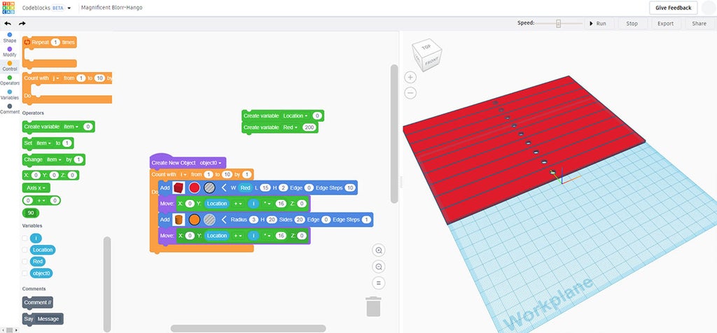
Drag the change operator onto the design area and position it before the end of the orange command block.
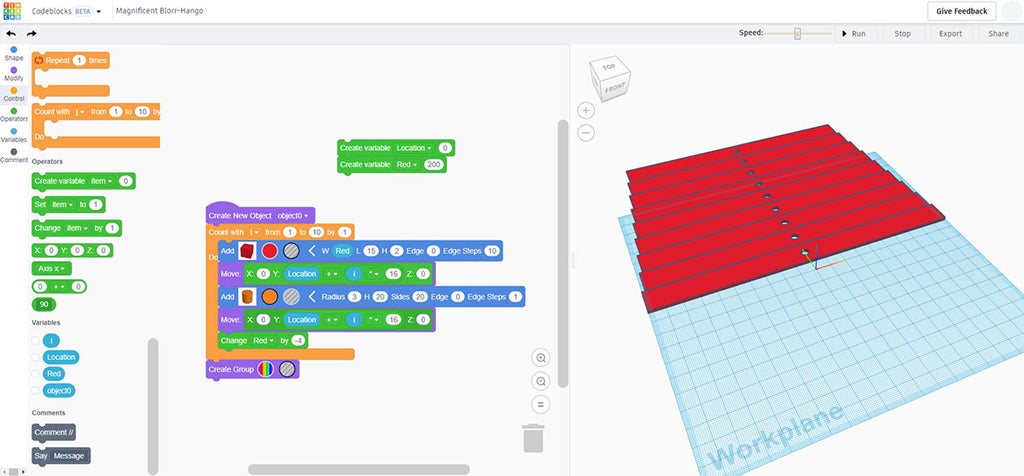
This operator will change the overall length by 4mm each time the command is run.
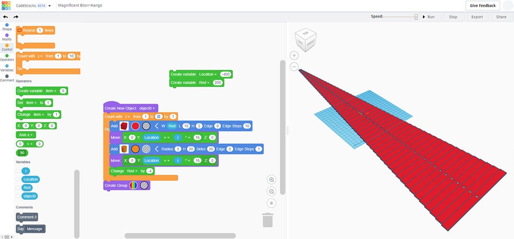
In order for the entire design to fit on the screen during simulation I added another operator command offsetting the start location. Running the simulation the rectangle decreases in length with each instance.
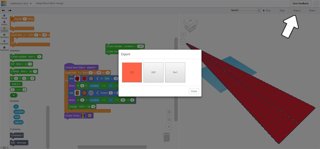
The entire design can be exported from Codeblocks as an STL file. We'll transfer this file over to the regular Tinkercad interface to modify the design to fit onto the laser cutter.
Step 6: Import to Tinkercad
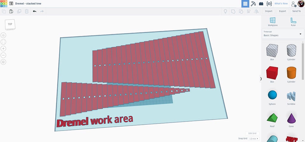
Import the STL to Tinkercad. If you're using the Dremel laser cutter I've already made a template that shows the cutting bed area, you can get that template here.
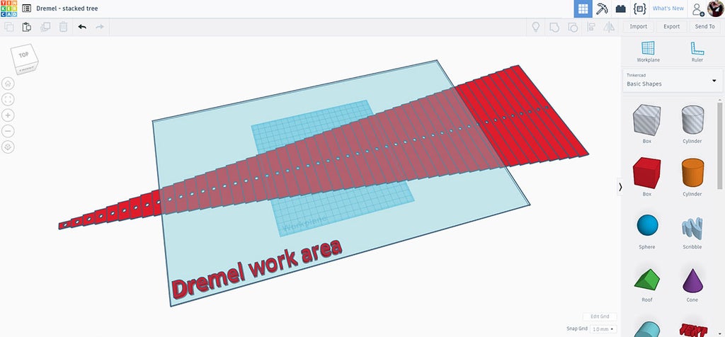
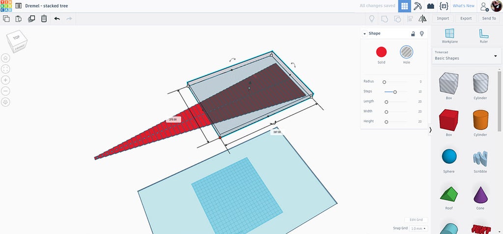
The design is too large to fit onto the cutting bed and will need some modification before cutting.
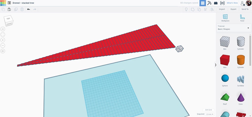
Drop in a hole box and stretch it over about half the design.
Then select both the design and the hole and make a copy (ctrl+D), move the copy next to the original.
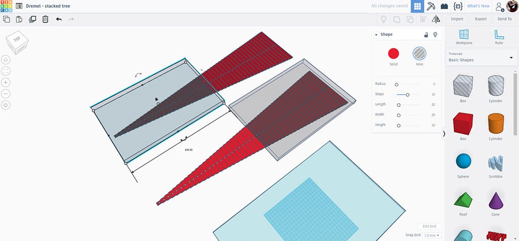
Select just the hole box on one of the copies and move the end handle from one side to the other, which will remove the other side of the deign.
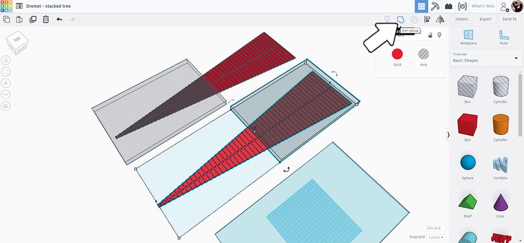
Select one design and hole box at a time and group them together. Repeat for the copy which has the remaining pieces and group again. You now have two designs that are opposite halves of the original.
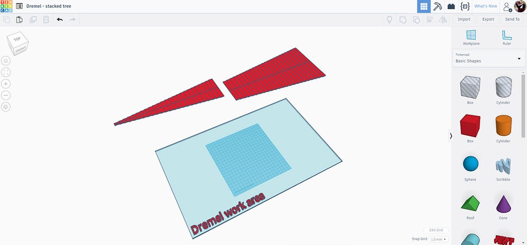
Grab each half and move them over the Dremel bed template to arrange them.
I flipped one side around to get them both to fit on a single sheet of plywood.

Select both halves and then export as SVG.
Step 7: Laser Time!

The Dremel laser has a material dropdown list that makes figuring out the laser power and speed settings simple.
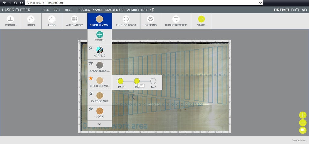
The exported SVG file can be put directly into the Dremel interface, which runs on any web browser window. There's no software to install, and the interface is super easy. A very common prototyping material is Birch plywood, which is listed in the dropdown from the top toolbar. Select the material thickness and you're ready to start cutting.
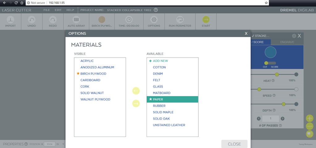
There's also a library of other materials you can choose from, each with their own power settings already set up. Choosing the more option at the top of the list allows you to sort and order your most commonly used materials.
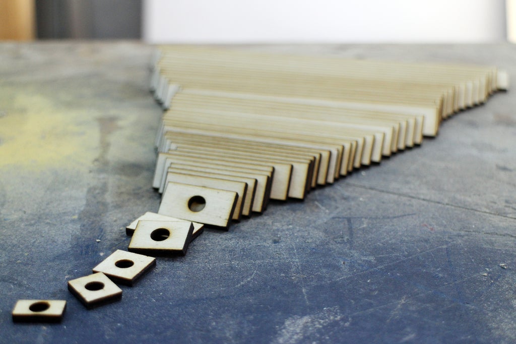
With everything set the laser could start cutting.

I cut this design out on ⅛" plywood. It took about 20 minutes to cut out all the shapes.
Step 8: Prime + Sand

The pieces were primed with a spray primer. Once dried the pieces were flipped and the other side was primed.
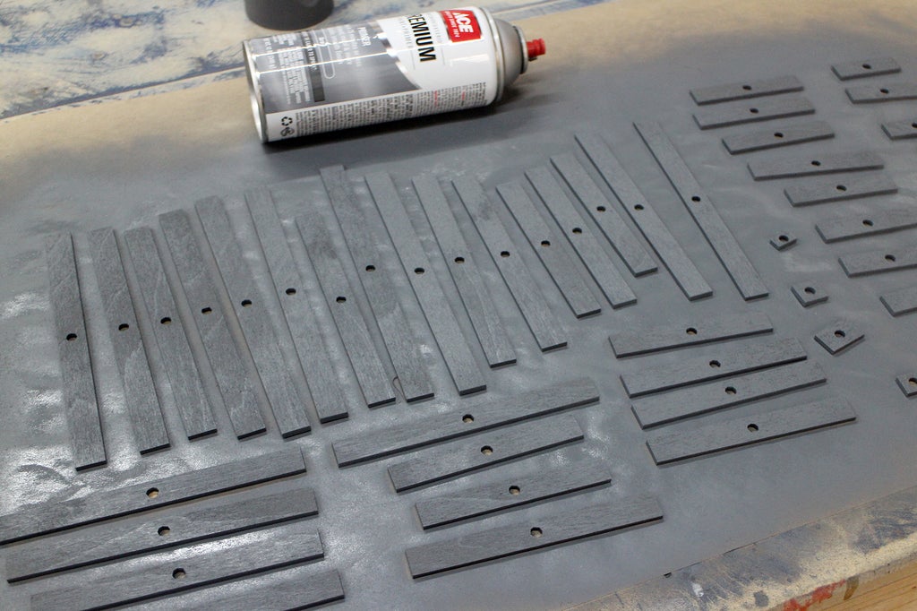
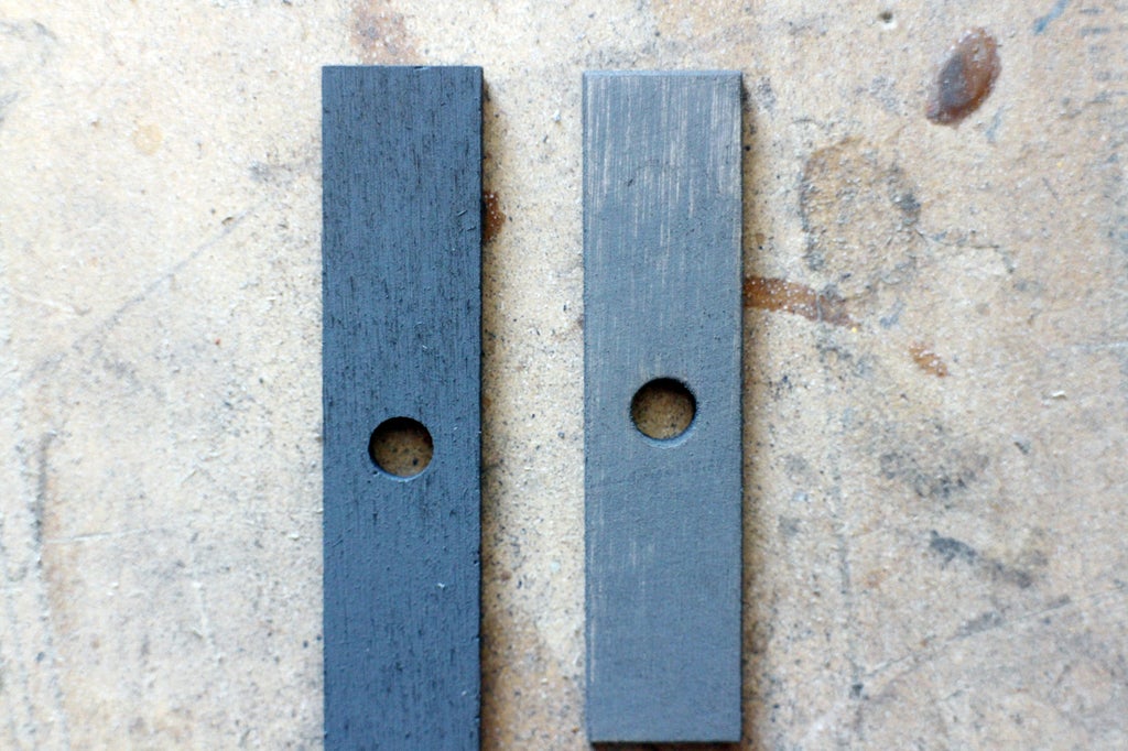
After priming the pieces were rough and needed snading to smooth the surfaces. This is an important step so the pieces will easily slide past each other when stacked on top of each other.
Step 9: Color

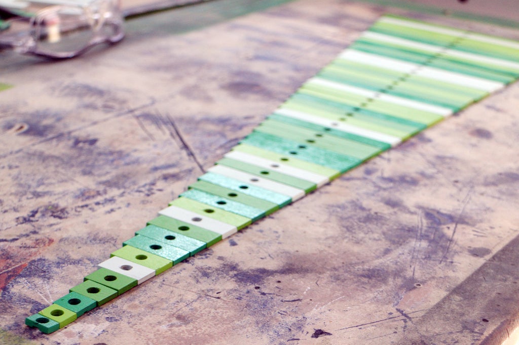
After priming and sanding the pieces were gathered up and roughly sorted into four piles. I made sure to mix up the lengths so that there wasn't too many repeating colors on consecutive pieces.

Here's what the pieces look like after 2 coats of paint.
After the paint has cured the pieces are ready to be stacked. I noticed that a few of the pieces were sticking together even after the paint had completely dried. A neat trick is to use a little talcum powder on each piece to prevent sticking and allow easy sliding when they are against one another.
Step 10: Base + Star

The base was made from a few cut pieces of plywood, using the same dimensions for the rectangular tree pieces. However, to keep the tree rigid the hole opening was made 0.5mm smaller. This stiffness allows the tree to stand upright.
 |  |
d
 |  |
The star was made by using a star shape in Tinkercad and adding a rectangle to it, then exporting as an SVG and laser cutting.
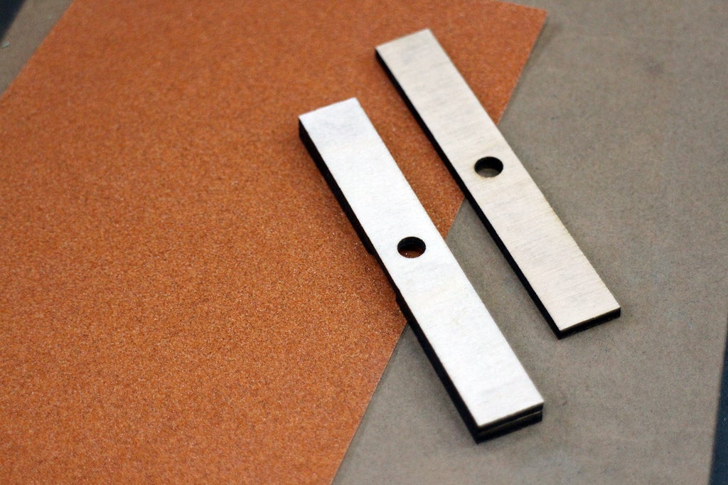
Since these pieces aren't painted, they were sanded to remove the scorch marks from the laser.
Step 11: Tree Time!


This desktop tree can have the branches arranged however you like, and can be packed flat for easy storage. Though I made this with a laser cutter, you could easily print the SVG files and cut each piece out by hand.

If you've been inspired by this idea I'd love to see it! Share a picture of your creation in the comments below.
Happy making :)


