

Introduction: Starting Up the ShopBot


Follow the below steps to start the ShopBot:
- Turn on the computer.
- Login using the name & password on the monitor.
- Do not turn on the ShopBot until you are logged in.
- Turn on the ShopBot.
- Open the ShopBot 3 program.
- Reset the E-stops.
- E-stop buttons are located next to the computer and on the pendant.
- Click OK.

Step 1: Stopping in an Emergency
There are two ways to manually stop the router when it is running: space bar and emergency stop (E-stop).
Pressing the space bar is the preferred method for quickly stopping the router.
- Pressing the space bar will:
- Stop gantry movement
- Bring the spindle to a stop quickly
- Allow the job to be easily restarted
- Using the E-Stop will:
- Stop gantry movement
- Kill power to the spindle. It will slowly coast to a stop and drop towards the table.
- Cause the router will lose its known position, and will need to be reset
Step 2: Safety Interlock Key
The safety interlock key must be inserted in the machine to enable the spindle. The key is attached to the spindle wrench to remind you.
Always remove the key before changing end mills.
- Removing the key will disable the spindle.
Step 3: Controller
The router is run by controller software on a Windows PC.
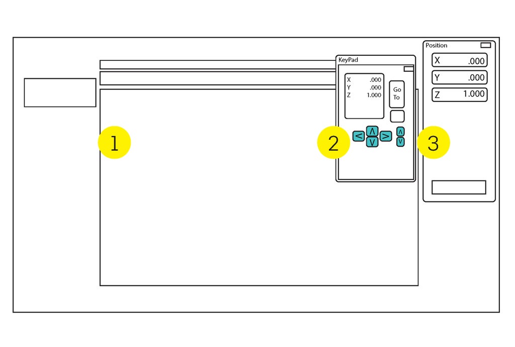
There are 3 main windows used to run the ShopBot.
- Command Console
- This is the main program interface.
- KeyPad dialog
- Used to manually move the gantry.
- Always close the keypad before operating the machine. Leaving it open will cause the controller software to crash.
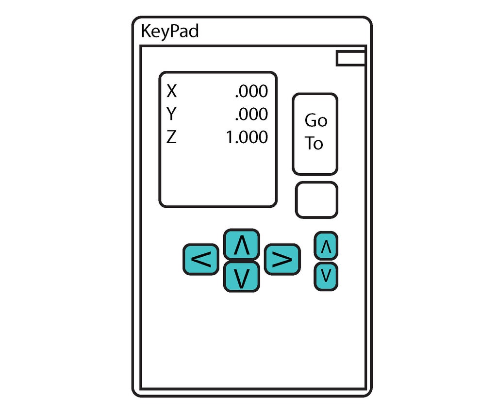
- Position Dialog
- Displays the current X, Y & Z coordinates.
- Has buttons to setup and run the ShopBot.
Step 4: Axis Labels
To help remember which direction is positive on the 3 axes, use the right hand rule.
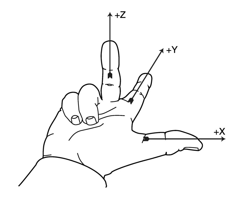
- Stand at the computer, looking at the long side of the machine.
- Hold out your right hand, like in the illustration.
- Each finger is pointing in the positive direction.
- The long axis is X.
- The short axis is Y
- Z is the vertical axis.
Step 5: Prepare the ShopBot

The following steps will have the machine travel to the limit switches on the X & Y axis, and reset the zero positions.
- Press the blue RESET button on the pendant.
- This locks the stepper motors and enables movement.
- Do not move the gantry by hand when the control box is on.
- Close the KeyPad dialog.
- Press C3 on the keyboard.
- Alternate: Select Cuts in the top bar, then C3 Home X & Y Axes.
- The gantry will move to the machine home position.
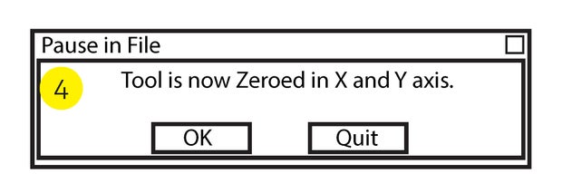
- A dialog box should open.
- Click OK.
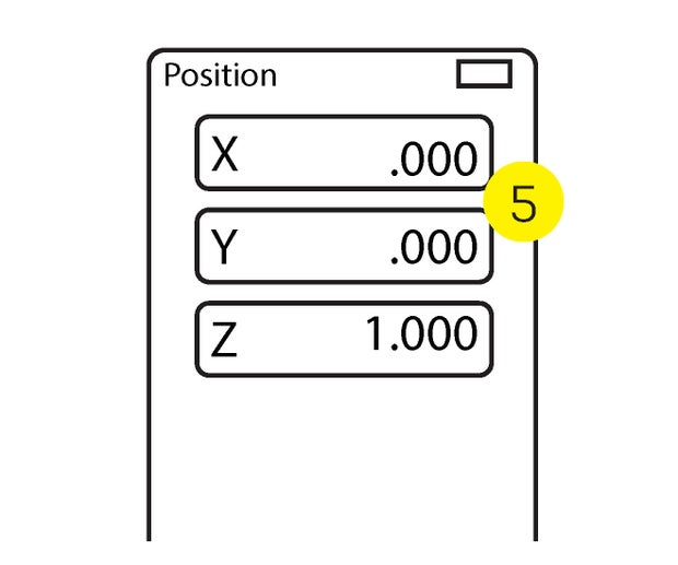
- Check the Position Dialog to con rm that X & Y values are 0 and Z is 1.
- See Shop Staff if the coordinates are incoVrrect.

Step 6: Jog the Spindle
The next steps will bring the spindle to a location where you can insert an end mill.
You can move the gantry with the KeyPad dialog.
- Press K to open the KeyPad dialog.
- Use the blue arrow keys to move the gantry.
- Close the KeyPad dialog.
Step 7: Safety Interlock Key
Before the ShopBot can rotate the spindle, the key must be inserted in the lock on the side of the controller box.
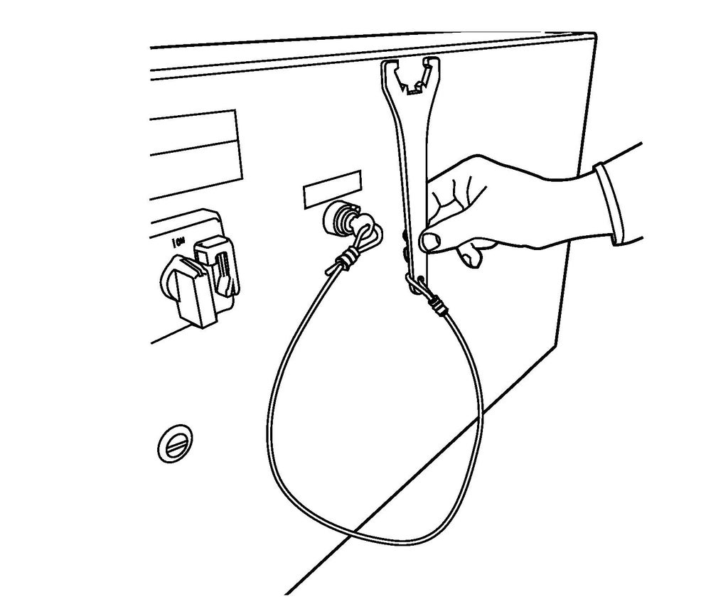
- If the key isn't in the lock, it should be in the second drawer of the ShopBot cabinet.
- The collet wrench is attached to the key to remind you to remove the key (and disable the spindle) every time you do a tool change.
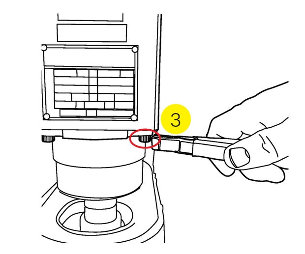
Step 8: Adjust the Dust Shroud
The dust shroud must be lowered to access the spindle.
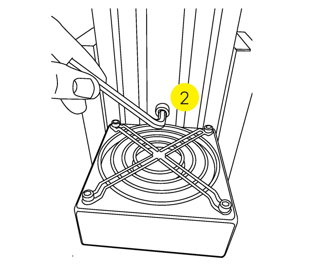
- Remove the key from the controller box.
- Loosen the Allen screw so the shroud can move.
- The wrench should be in the top drawer.
- Lower the shroud to access the spindle.
Step 9: Insert the Tooling
The shank of the end mill must be the same size as the collet.
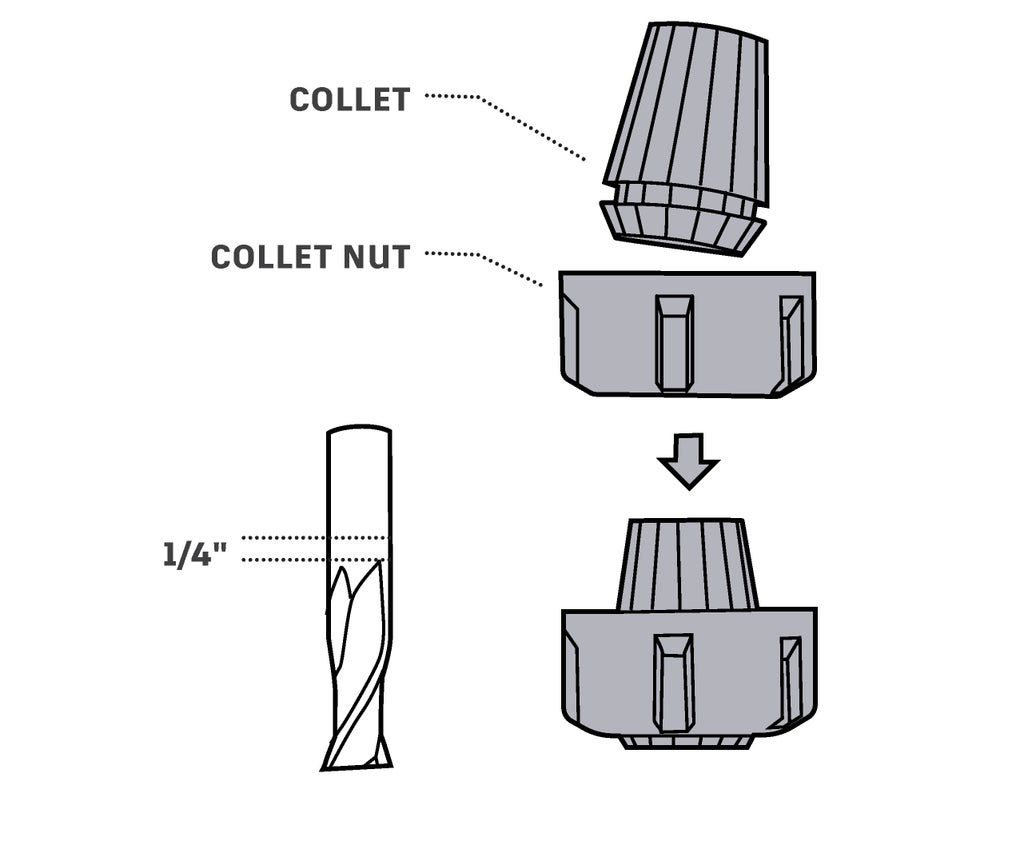
- Tap the collet on a piece of wood to knock out any sawdust.
- Snap the collet into the collet nut.
- Loosely thread the collet nut onto the spindle.
- The threads are very fine. It's easy to cross- thread the spindle. Be careful.
- Slip the end mill into the collet.
- Hand tighten the collet nut.
- Leave 1/4" of shank sticking out of the collet.
- Tighten the collet with the wrenches.
- "Monkey tight” not “gorilla tight”
- Adjust the dust shroud.
- The top of the shroud should be even with the top of the collet.
To remove the bit, loosen the collet nut and put away the bit and tools.
Step 10: Set Zeros

Carefully measure the material thickness before entering it into the CAM software.
It is important to not damage the table. These steps will help avoid mistakes.
- If you are cutting all the way through your material, limit your cut to an extra 1/32"
- Carefully measure the thickness of your material and enter the value into your CAM software.
- Use the Zero Plate to nd Z Zero (the exact top of your material).
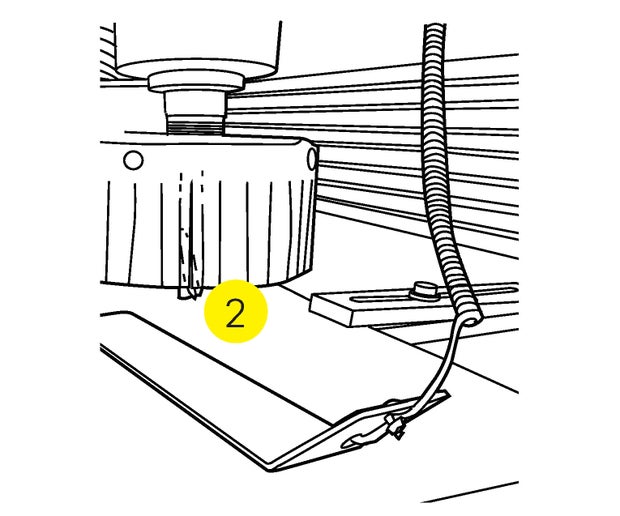
Set Z Zero
- Jog the spindle over your workpiece.
- Place the Zero Plate under the end mill.
- Attach the ground clamp to the standoff on the spindle.
- In the [C]uts menu, select C2 - Zero Z axis w/ Zero plate.
- Press Enter when you are ready to set Z Zero.
- The spindle will lower until the end mill touches the Zero Plate twice.
- If it fails, restart the software.
- Not closing the control panel will cause it to fail.
- Remove the ground clamp, and put away the Zero Plate.

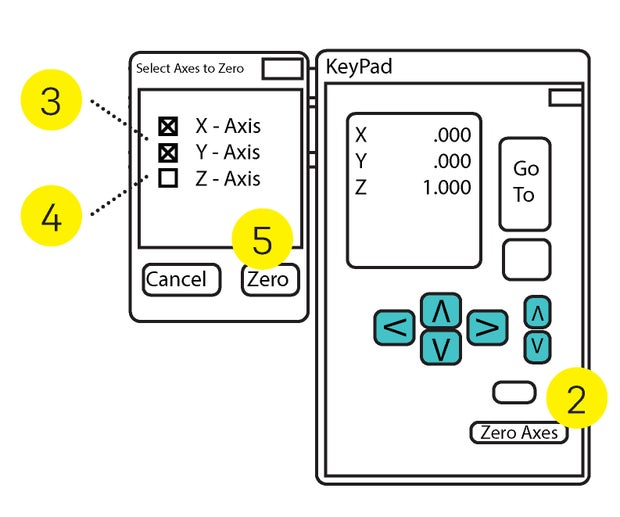
User Home
User Home is a user defined zero point. It's the same point that you defined in your CAM software as X0, Y0.
To set the User Home:
- Jog the spindle to the bottom left corner of your material.
- Taking a photo of the computer screen will allow you to return to the same spot in the event of a crash.
- Click Zero Axes in the KeyPad dialog.
- Select X & Y.
- Ensure that Z is not checked.
- Click the ZERO button.


