

Introduction: Tape Measuring Tool


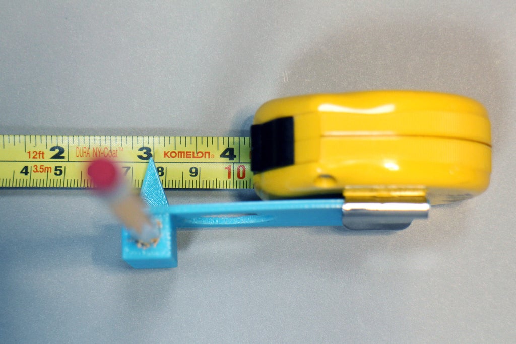
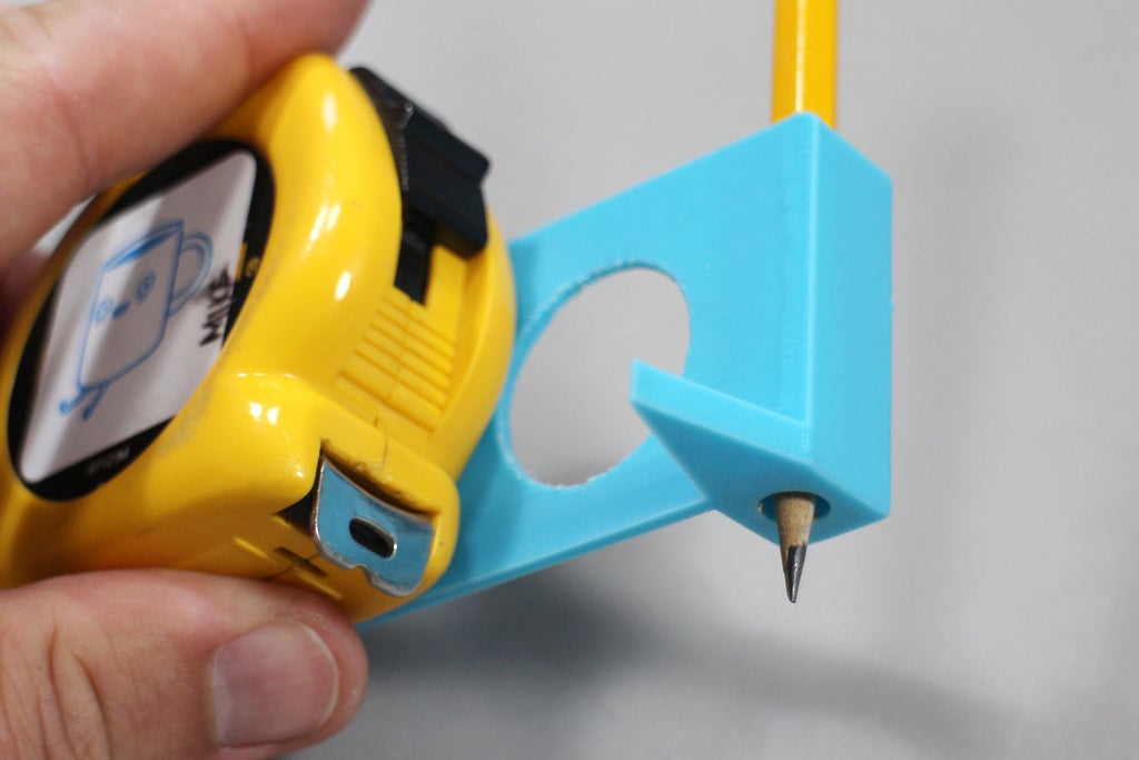
This handy tape measure add-on allows you to measure and mark with one hand. A 3D printed pencil holder attaches right to the tape measure body, and an arrow aligned with the pencil easily shows where the mark will a land.

I made this with Tinkercad, a free and easy to use 3D modeling tool that runs right in your web browser. Tinkercad is great becasue you are just dragging simple shapes around to make your creation, kind of like building something with LEGO. Though this colorful software is very easy to learn, the ceiling of what it can do is actually very high, as long as your design can be managed with the primitive shapes provided.
I made a few versions of this design, and you're welcome to check it out and make it your own.
This model will probably work with any tape measure, provided the clearance between the mounting opening and the arrow is wide enough. Grab the STL file below and try it yourself, or follow along in this Instructable and I'll show to make your own.
Ready? Let's make!
Attachments

Step 1: Measure Tape Measure

Before any modeling I made some measurements and notes about the tape measure I wanted to put the pencil holder on.
I used the screw for the belt loop as the anchor point for almost every dimension. Some critical dimensions for this build:
- Horizontal distance from attachment screw to where I wanted the arrow
- Vertical distance from attachment screw to the tape aperture
- Diameter of a pencil
Since 3D printing happens on such a small scale, and working with whole numbers is much easier than fractions, millimeters is the conventional unit of measurement. Almost all calipers will have a unit button that will allow you to easily switch between imperial and metric. With these dimensions I could start modeling.
Tinkercad is browser based, so all you need is a computer and access to the Internet. After getting a free account to keep your models in, you're good to go!
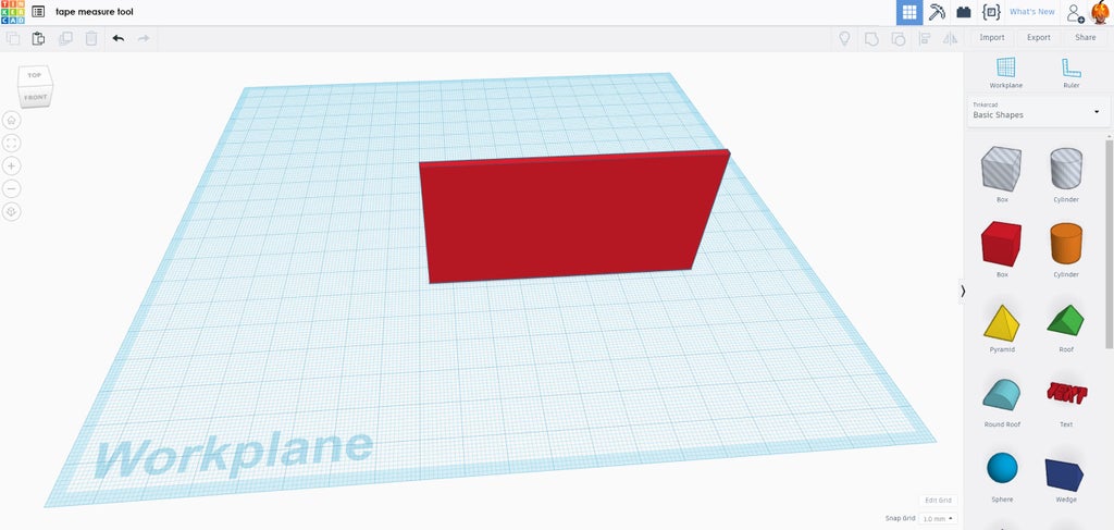
Step 2: Start With a Box

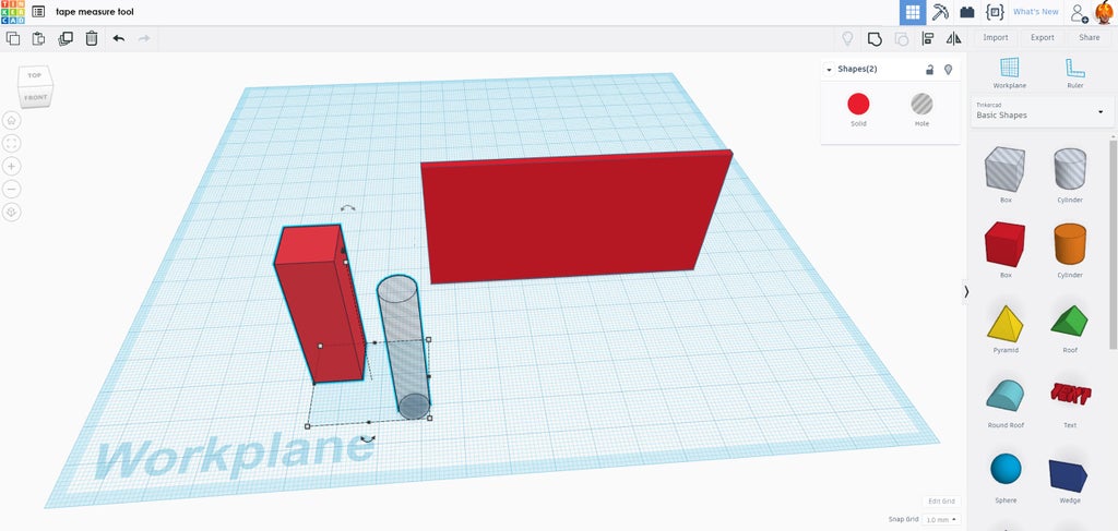
Tinkercad uses colorful primitive shapes to create objects. These primitives can be modified in all kinds of ways to make shapes. To start this design, drag a box from the Basic Shapes bar on the right side of the screen onto the Workplane.
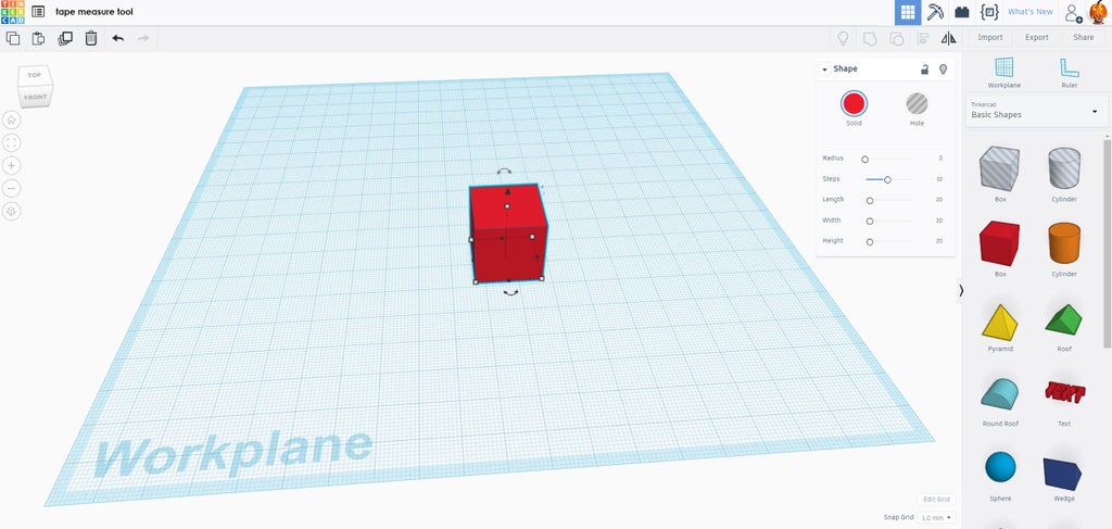
When a primitive is dropped onto the Workplane there are white nodes around the shape, these are handles that allow the shape to be manipulated to suit your needs.
Step 3: Modify the Box

The box is a good start, but we want more of a flat rectangular shape for the tape measure tool.
Clicking on one of the white handles on the bottom of the box will allow you to see the measurement of this primitive, this box is 20mm by 20mm. These numerical values can be clicked on and replaced by your own values. A quick way to switch between the length and width values is the TAB key.
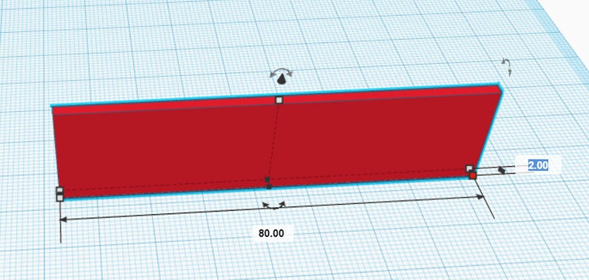
This rectangle will be the flat part that attaches to the side of the tape measure. Since all other shapes will be attached to this rectangle, it's a good place to start. The dimension values were changed to 80mm long and 2mm thick.
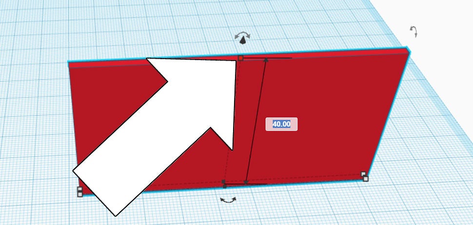
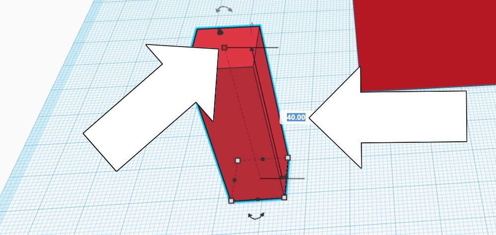
The white handle on the top of the shape allows the height to be changed. Click on the top white handle, push TAB to enter a new value of 40mm.
We now have a skinny and wide rectangle shape. Great job!
Tinkercad works by combining shapes to create your vision. The process of dropping new primitives and changing the dimensions is how we're going to create the tape measuring tool.
Step 4: New Box - Pencil Holder

To make the pencil holder drag a new box primitive from the Basic Shapes bar on the screen onto the Workplane.
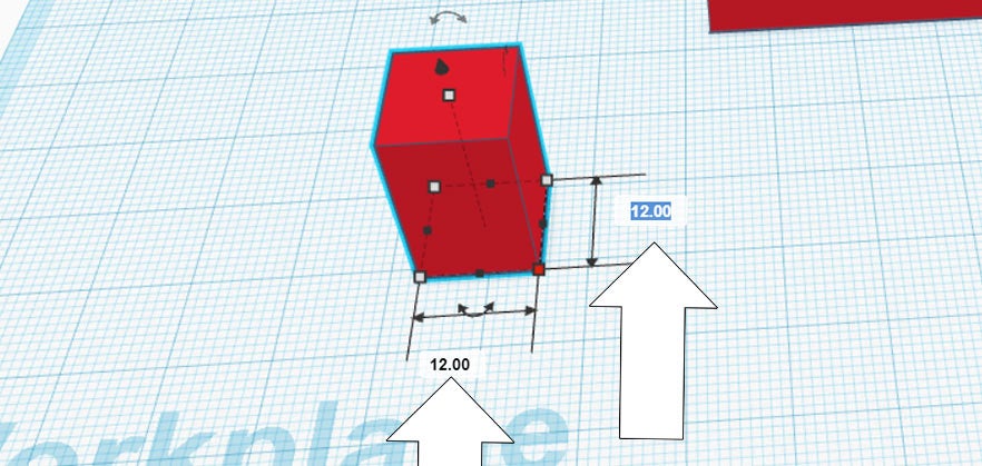
Click on the new box to bring up the white handles, then push TAB to quickly get into the dimension value area. I made this new box 12mm by 12mm.
Click the top white handle and push TAB to enter the new height. Matching the rectangle we made earlier, a value of 40mm is entered.
Step 5: Pencil Opening

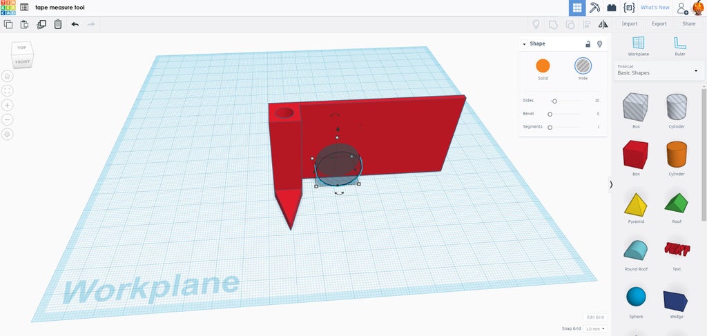
Now that there's a box for the pencil holder there needs to be an opening to insert the pencil. In the Basic Shapes bar on the right of the screen there are two ghostly shapes, a box and a cylinder. Drag a ghostly cylinder onto the Workplane.
When combined with solid shapes, these ghostly shapes carve out whatever they are touching. This ghostly cylinder will go inside the pencil holder box we just made, but first we need to give it the correct dimensions of a pencil.
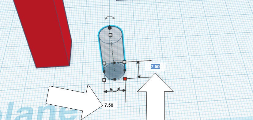
Ghostly shapes can be modified just like regular primitives. Click on the ghostly cylinder and push TAB to enter new values. I measured the pencil I was using at around 7.5mm in diameter, so 7.5 was entered in for both values.
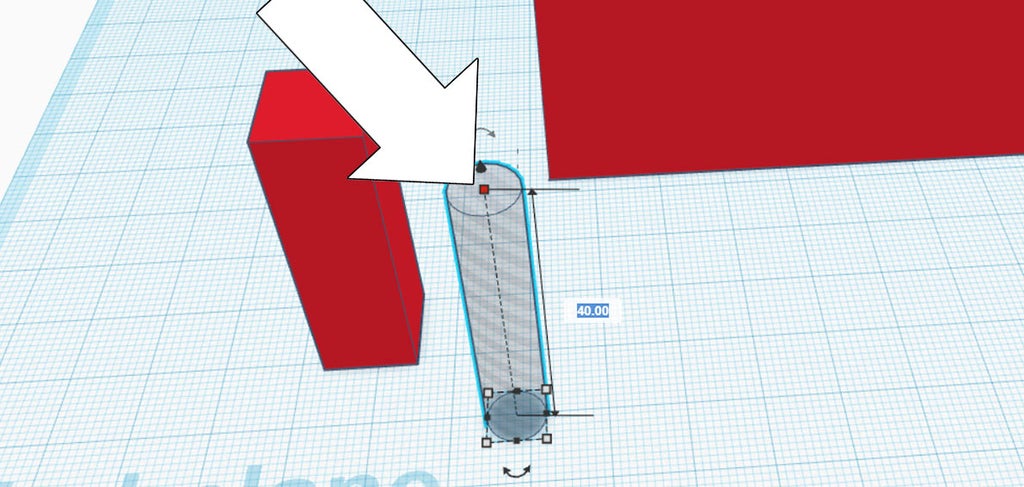
Clicking the top white handle a new value of 40mm is entered, matching the height of the pencil holder box.
The tall pencil holder box and tall ghostly cylinder are going to be combined to create the space inside the holder.
Step 6: Align Pencil Holder Shapes

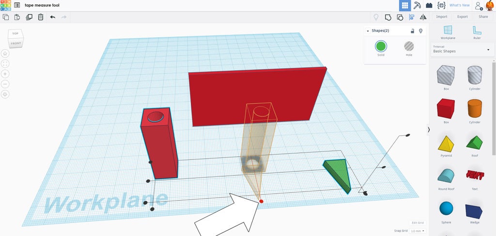
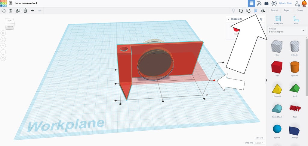
Click and drag the mouse to create a window around the tall rectangle pencil holder and the ghostly negative shape. You may have to move the view around to just select those two shapes. With both shapes selected find the align button at the top of the screen in the toolbar - it looks like two bars stacked on top of each other.
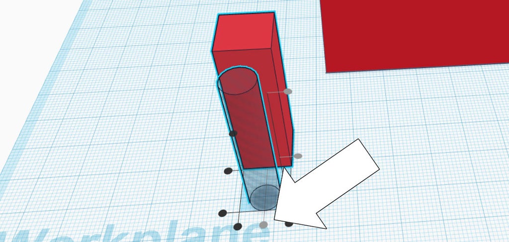
Clicking align when shapes are selected allows the two shapes to be aligned with each other. The window around the two objects has changed from a dashed line to a solid outline with round black nodes surrounding the shapes. Clicking the center node will center align the shapes in one direction.
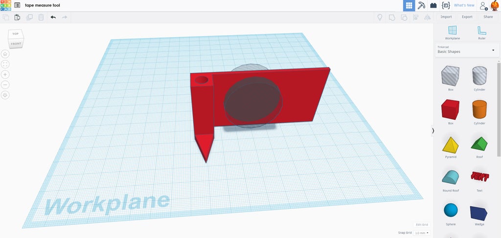
Clicking on the center node on the other direction will align them again, putting the cylinder directly in the middle of the pencil holder. Click on any blank space in the Workplane to stop the align command.
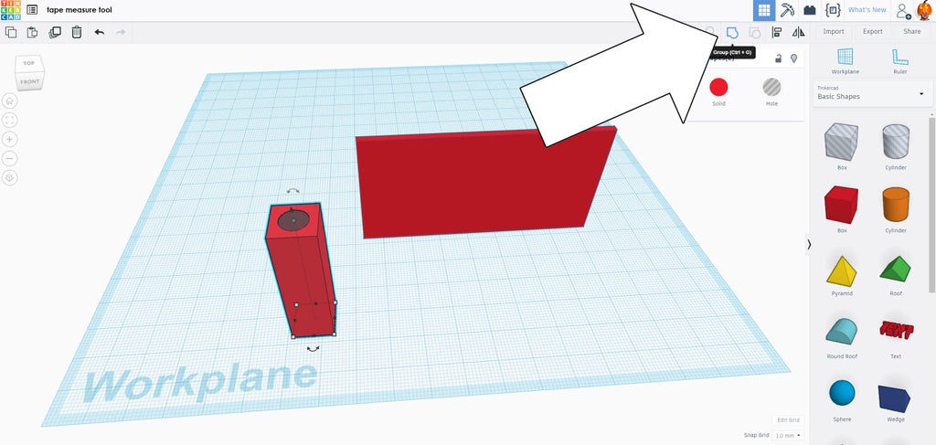
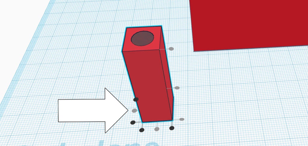
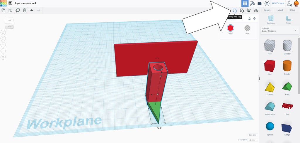
To create the void inside the pencil holder we'll combine your centered shapes. Click and drag a box around the pencil holder and centered ghostly cylinder. With both selected, click the group button in the toolbar at the top of the screen. The shapes will combine, adding the negative space of the cylinder to the solid pencil holder rectangle, creating a cylindrical void.
Step 7: Measurement Pointer

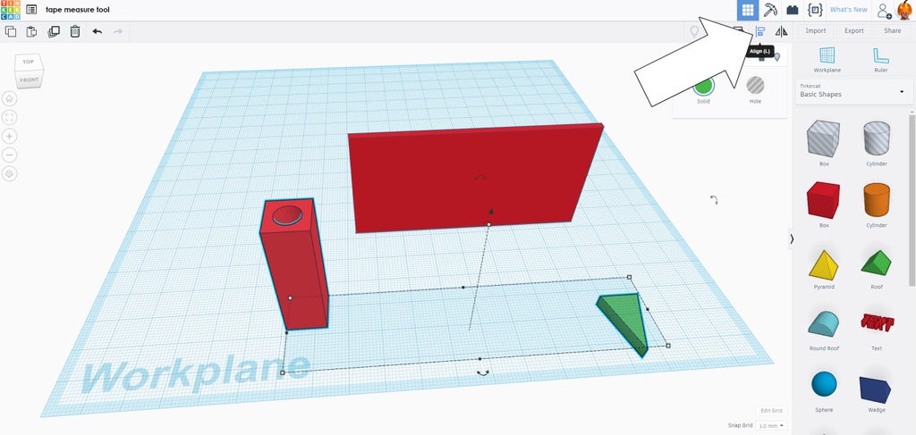
For the measurement pointer I used the roof primitive, which was dragged and dropped from the right side of the page and onto the Workplane.
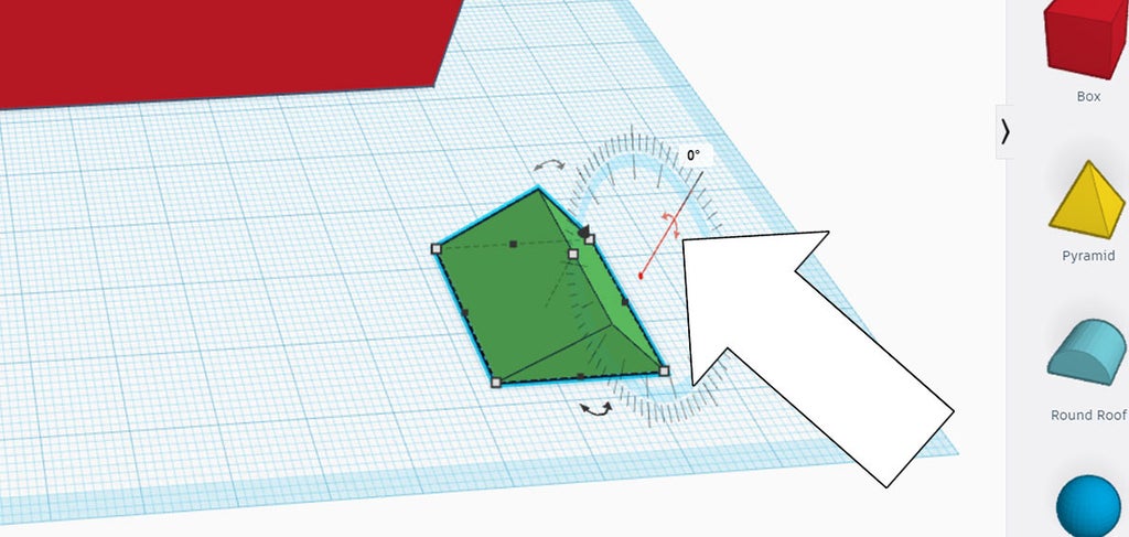
Along with the white nodes that appear on a primitive are rotational arrows, seen just outside of the model. These rotational arrows correspond to an axis, so you can only rotate a model in one axis at a time - which keeps things very easy.
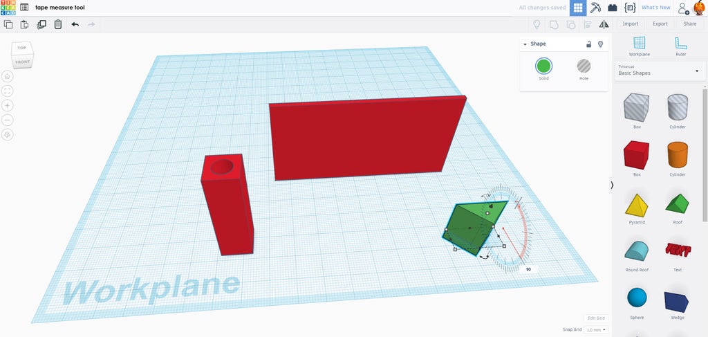
Click the rotational arrow to the side of the model to rotate the roof to stand on its end, making it look like a long rectangular prism. If you hold down shift while you rotate the primitive will rotate and lock at logical incremental degrees, like 45°and 90°, alternatively hitting the tab key will allow you to enter in a numerical value. We want a 90° rotation.
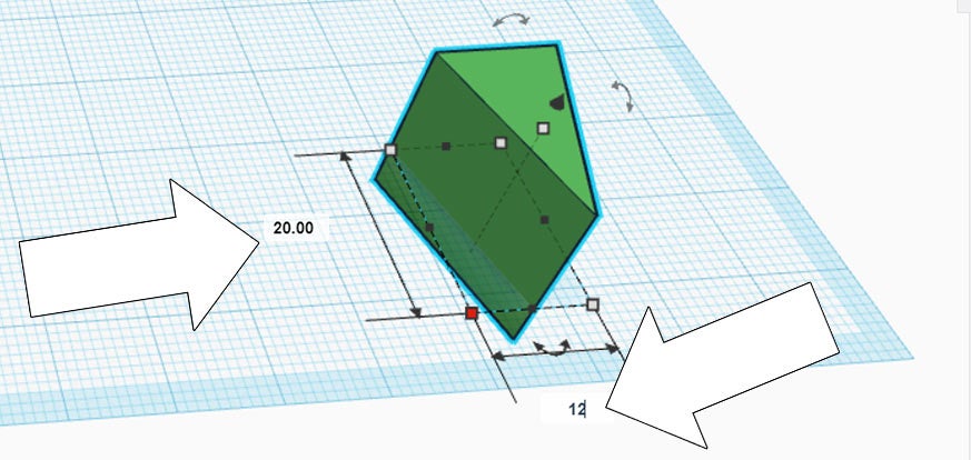
After rotating, the white nodes can be modified to create the measurement pointer. I chose a 20mm long pointer with a base width of 12mm, the width matches the width of the pencil holder.
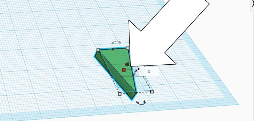
Clicking the white node on top to lower the height profile, I made the pointer 4mm high.
Step 8: Align Pointer to Pencil Holder

To align the pointer and the pencil holder, drag a window around both shapes to select them. In the top right of the toolbar is the align command. Click align to bring up the positioning nodes.
We want the shapes to be aligned, so chose the middle node to place the shapes in line with each other.
Since there's no command to place the edge of one shape at the end of another, the shapes can be manually positioned to have the base of the pointer at the edge of the pencil holder. Use the align tool if things get away from you.
With the two shapes aligned they can now be combined to form one shape.
Drag a window around both, then find group in the top right toolbar to create one shape from the two selected.
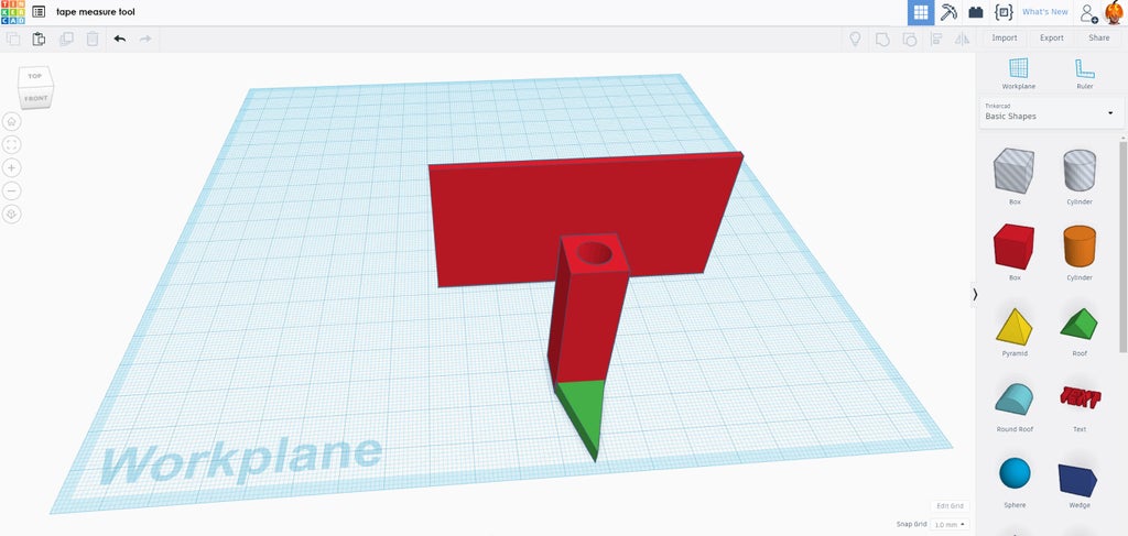
Step 9: Align Pencil Pointer to Long Box

The pencil pointer shape can be manually moved to the long box, lining the pencil pointer on one end of the box, or the pencil pointer and box can bother be selected and matched up using the align button in the toolbar.
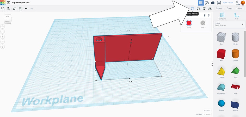
Once positioned, select both objects and group to make them one shape.
Step 10: Add Void

To save printing filament, and speed up the print time, a large void was added to the middle of the long box. This part is optional, but there's no reason to have it solid, and it's a good exercise in modeling.
From the primitives library on the right grab a hole cylinder and drop it onto the Workplane.
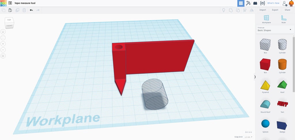
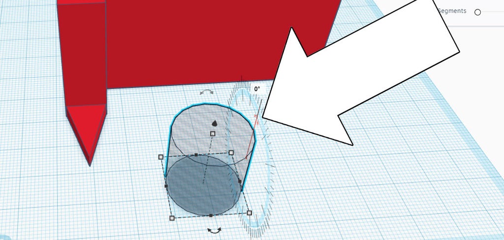
Click on the cylinder to bring up the rotational arrows, and rotate the cylinder 90°.
Move the cylinder into the long box. The relative location of the opening doesn't matter right now, as the align tool will help us center it after the size is right.

Once in place, the cylinder was modified to almost fill the long box area. I sized the cylinder to be 5mm less than the height of the long box, so if the height of the long box was 40mm the cylinder was 35mm.
A window was dragged around both shapes and the align tool was chosen. The cylinder needs to be vertically centered in the box, to do this the middle height node was chosen.
With the large cylinder centered in the box the shapes can be grouped to create the opening.
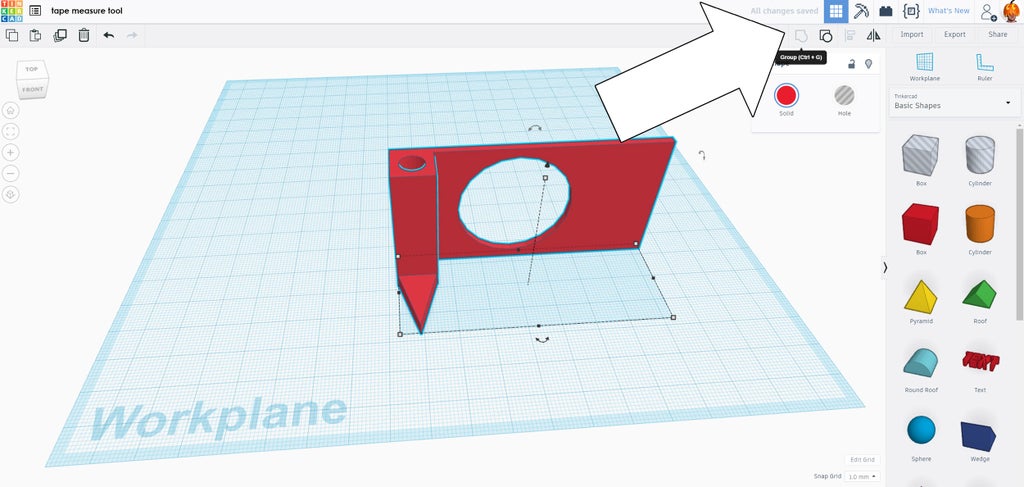
Select both shapes again and use the group command to make the opening in the long box.
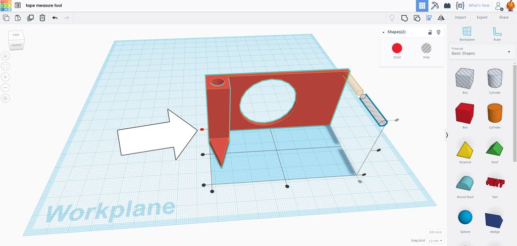
Step 11: Screw Opening

With the basic shape finished the screw opening can be placed. Drop a new hole cylinder into the Workplane.
Click the primitive to bring up the white nodes, and enter in your screw diameter value, I used 3mm x 3mm.
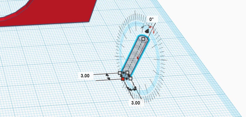
Using the rotational arrows the cylinder was rotated 90°.
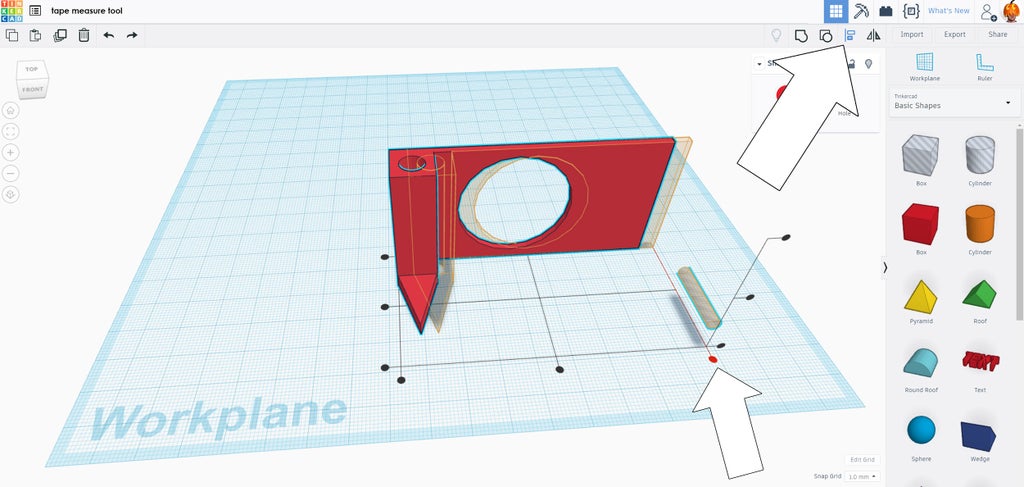
Select the tape measure tool model and the new hold cylinder, then chose the align command from the top toolbar.
The screw opening is located in the upper right of the solid model, so the position node on the end was clicked to being the hole cylinder to that end.
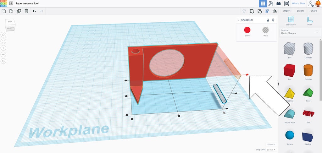
The top vertical alignment was then chosen to bring the cylinder to the top right of the solid model.
With the cylinder in the right position the two shapes were then brought in line using the far back alignment node, bringing the cylinder into the body of the solid model.
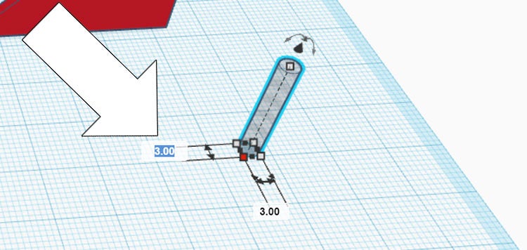
The hole cylinder is aligned correctly to the solid, but in the wrong location.
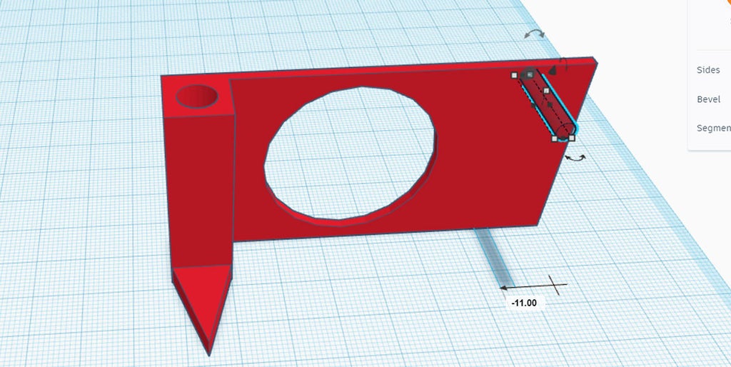
Click the cylinder and start dragging it to the left, a numerical value will appear below the shape and indicate how far the shape is in relation to where it was before you started dragging. Push tab to get into the value field and type in the measurement made from your notes (mine was 11mm from the edge).
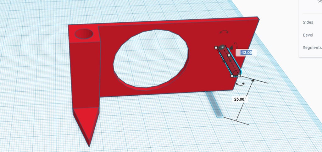
Repeat the same process by dragging the hole cylinder downwards, then pushing tab and entering in the value from your notes (mine was 12mm from the top). The 25mm shown in the image above is referencing how far away the hole cylinder is from the surface of the Workplane.
With the hole cylinder in the right location, both shapes can be selected by dragging a window around them and then grouping them.
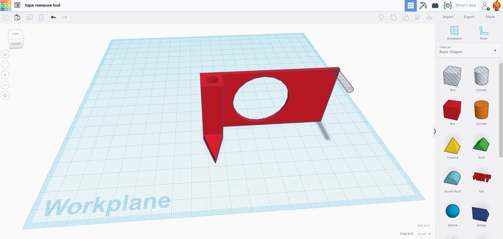
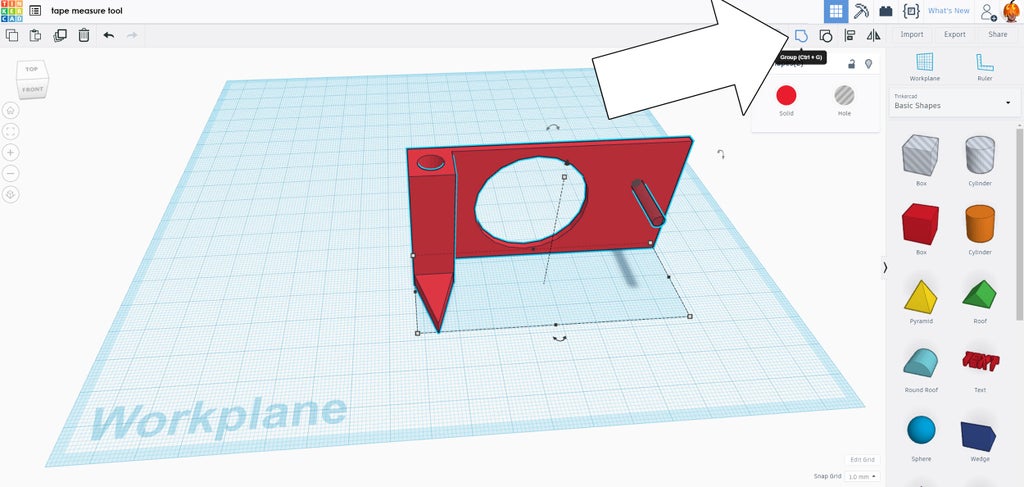
Step 12: Export Model

The model is now complete! Check out the model from all sides to make sure you're happy with how it looks. If there's any areas they need work, select the model and chose ungroup to break the model apart.
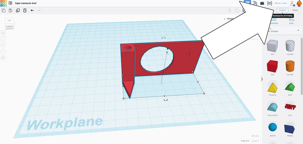
Select the model and find the export button in the top right of the screen. This will take you to the printing screen.
Step 13: Send to Print

Some 3D printers are connected to a laptop, and some use an SD card. Whichever method, export your model and start printing. There's loads of choices for 3D printers, if you're looking for a great deal the Creality 3D printer is inexpensive and a workhorse of a printer.
This model took about 30 minutes on standard settings. You can download my STL file below, or you can play around with it in Tinkercad. Remember, this model was measured for the tape measure I had on hand, yours may have different measurements.
Attachments

Step 14: Clean Print

3D prints rarely come off the print bed perfect. Luckily, cleanup is straightforward.
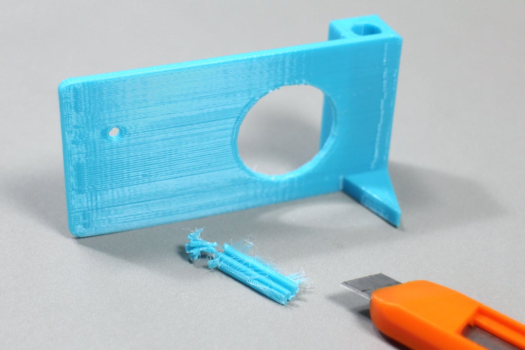
A sharp hobby knife was used to clean stay wisps of plastic from the print, and to remove the support structure from the large void in the middle.
Step 15: Attach to Tape Measure

My tape measure has one small screw that holds the belt clip to the back. Using a screwdriver the screw was removed and the belt clip was slid over the 3D print, lining up the small screw openings.
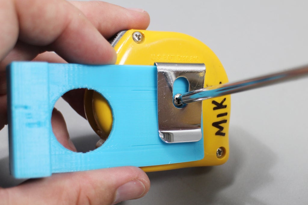
The screw was then inserted into the 3D print and belt loop, and fastened to the tape measure.
Step 16: Start Measuring!

This measurement tool works either as a one-handed marking tool, or just a place to hold your pencil while you're measuring.
This model is completely open-source, so download and print it yourself, or use it as a base to make your own. You can open this model in Tinkercad by following this link, in case you want examine some details, or copy it to your own portfolio.
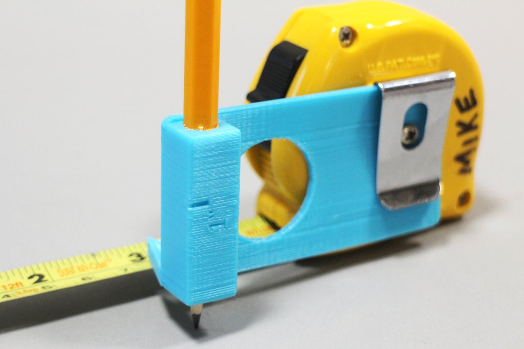
On a further revision I made a 1" notch on the pencil holder to give a quick reference without opening up the tape measure, if I ever needed it.
Happy making! :)
Have you made your own tape measure tool?I want to see it!
Happy making :)
Attachments


Participated in the
Plastics Contest


