

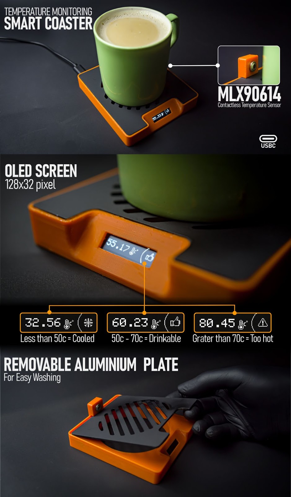
Introduction: Temperature Monitoring Smart Coaster


It's the perfect time of year to stay warm and cosy with a hot cup of tea or coffee. However, it's important not to make it too hot as it may burn your mouth. That's why I made a Temperature Monitoring Smart Coaster. This smart coaster can monitor the temperature of your beverage in real time and notify you when it's at a drinkable temperature. You can easily customise the temperature range using the provided code.
The current setting in the code is
Less than 50c = Cooled
50c - 70c = Drinkable
Grater than 70c = Too hot
We are using the Infrared Temperature Sensor GY-906 MLX90614 to sense temperature. The results will be displayed on a small OLED screen. The Seeed Studio XIAO SAMD21 controls all of these components. Most parts of this project were created using 3D printing technology. If you're interested, I can show you how it was constructed.
Supplies
Parts
- Seeed Studio XIAO SAMD21
- 0.91 Inch 128x32 OLED LCD Display
- Infrared Temperature Sensor GY-906 MLX90614
- 6*CSK Allen M3 x 10mm
- 30Awg connecting wires
- Spray paint matt black
- USB cable paired with a phone charger
Tool
- Allen key
- 120 grit sandpaper
- 3d printer
- Soldering kit
- Glue gun
Step 1: Modeling in Autodesk Fusion 360

I used Fusion 360 for planning and designing this, but I am not fully getting into how I modelled it, we will look at how I exported the laser-cut metal parts of this project, and we will discuss it in the next step, you can skip this step if you need. all design files are given below


Step 2: Exporting Laser-cut DXF Files From the Fusion 360
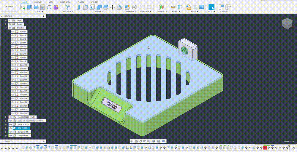
- After completing the full 3d model of this design, I just isolated the aluminium part for easy working.
- I hit “P” on my keyboard for projection mapping and selected the front face this will project the front face into a new sketch.
- Go to the sketch tab and find the projected sketch
- Right-click the sketch and “Save as DXF” . and select a path to save it in your PC
- Find an online or offline laser-cutting service that is accessible to your location. I am using Robu.in because I am in India. share these files to them
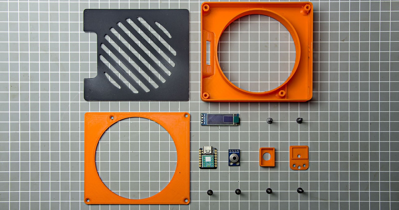
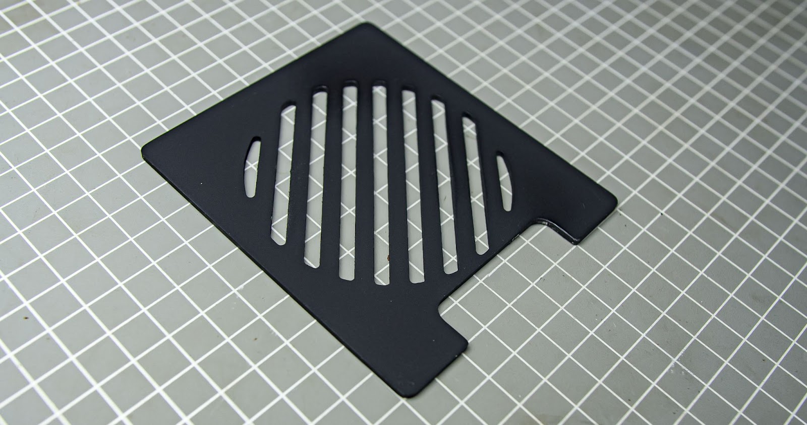
Step 3: Preparing the Top Plate
We are using an aluminium plate to avoid melting our 3D print
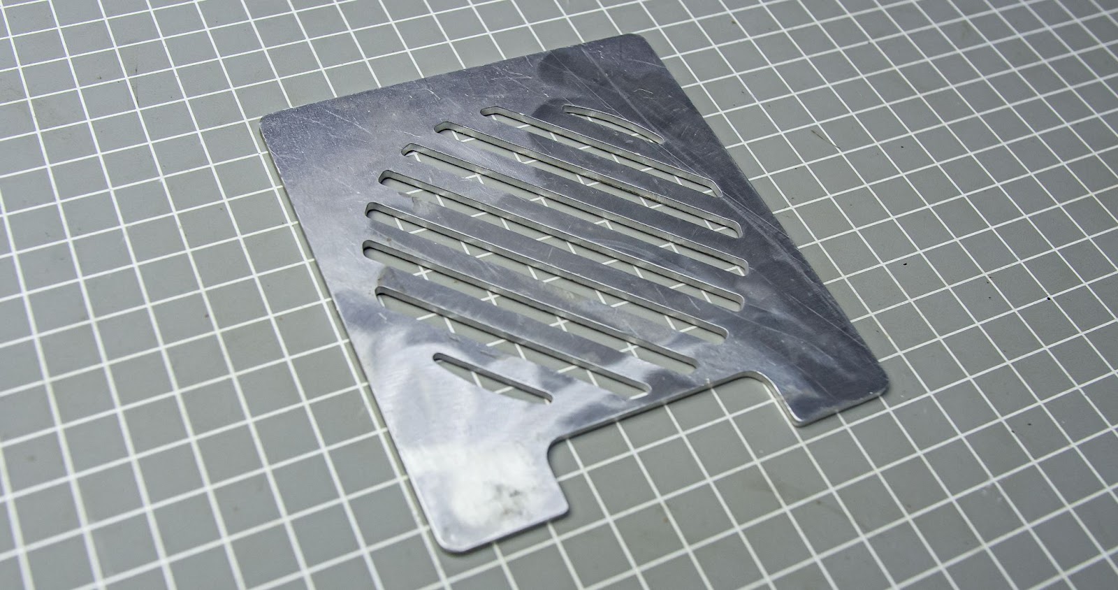
After receiving the aluminium part, we need to sand both sides with 120-grit sandpaper lightly. which will remove the oxides also the paint will stick better
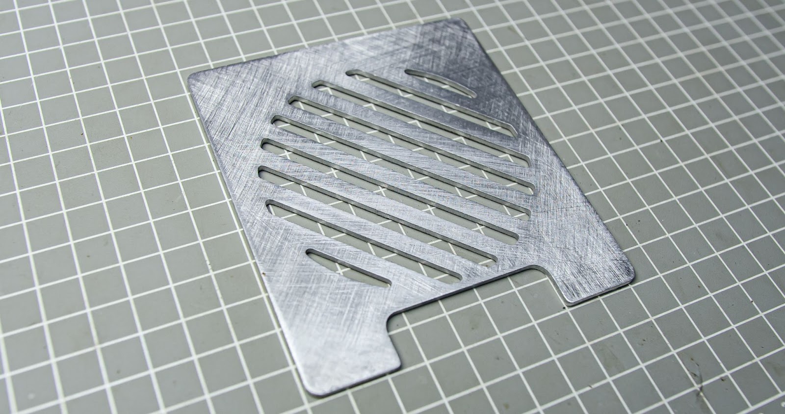
After sanding we need to spray paint it 2 coats and leave it to dry
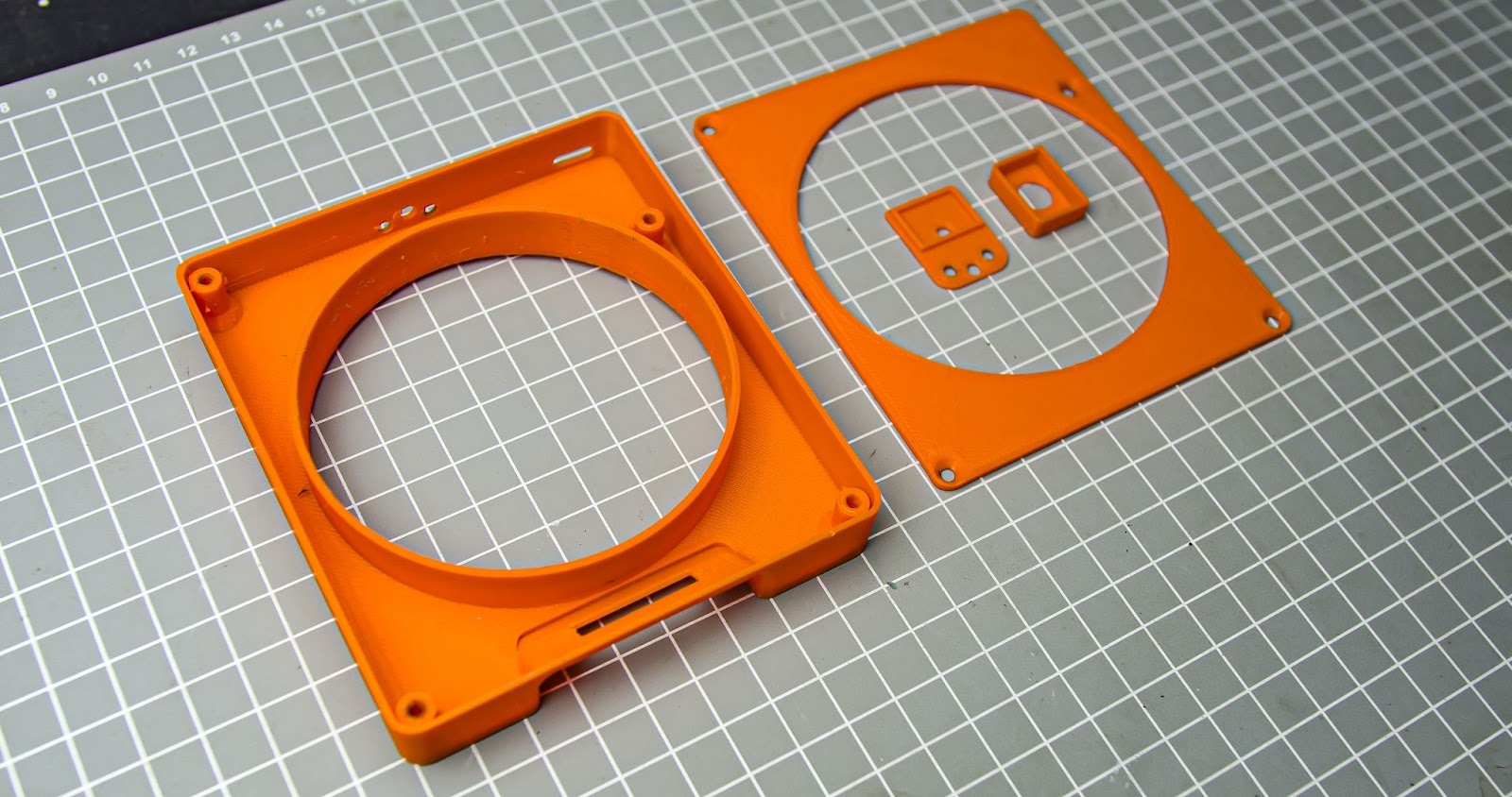
Step 4: 3d Printing Parts
We also need to 3d print some parts for this project. i printed mine with my Anycubic Kobra 2 neo 3d printer .all files are available at Step 1
Step 5: Uploading Code to XIAO
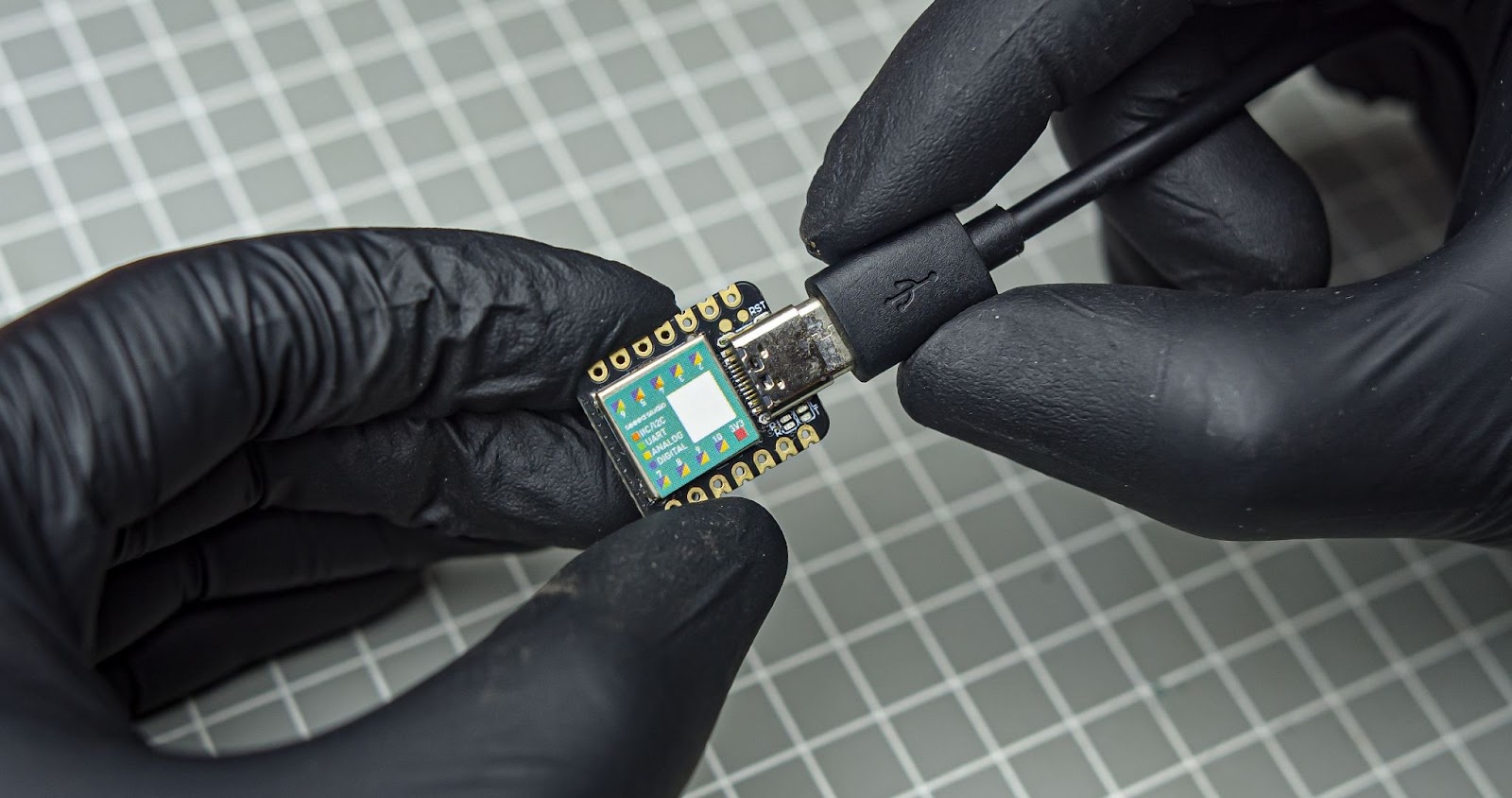
I always like to upload the code to the microcontroller before assembly. I am using Arduino IDE for flashing the code. follow these tutorials for setting up IDE for Seeed Studio XIAO SAMD21 and learn more about this board
Please download and install the Adafruit_MLX90614.h library before compiling
How to install library tutorial video link
The code
#include <Wire.h>
#include <Adafruit_MLX90614.h>
#include <Adafruit_GFX.h>
#include <Adafruit_SSD1306.h>
#define SCREEN_WIDTH 128 // OLED display width, in pixels
#define SCREEN_HEIGHT 32 // OLED display height, in pixels
#define OLED_RESET -1 // Reset pin # (or -1 if sharing Arduino reset pin)
Adafruit_SSD1306 display(SCREEN_WIDTH, SCREEN_HEIGHT, &Wire, OLED_RESET); //Declaring the display name (display)
Adafruit_MLX90614 mlx = Adafruit_MLX90614();
static const unsigned char PROGMEM image_weather_temperature_bits[] =
{0x1c,0x00,0x22,0x02,0x2b,0x05,0x2a,0x02,0x2b,0x38,0x2a,0x60,0x2b,0x40,0x2a,0x40,0x2a,0x60,0x49,0x38,0x9c,0x80,0xae,0x80,0xbe,0x80,0x9c,0x80,0x41,0x00,0x3e,0x00};
static const unsigned char PROGMEM image_weather_frost_bits[] =
{0x01,0x00,0x13,0x90,0x31,0x18,0x73,0x9c,0x09,0x20,0x05,0x40,0x53,0x94,0xfe,0xfe,0x53,0x94,0x05,0x40,0x09,0x20,0x73,0x9c,0x31,0x18,0x13,0x90,0x01,0x00};
static const unsigned char PROGMEM image_hand_thumbs_up_bits[] =
{0x00,0x10,0x00,0x28,0x00,0x28,0x00,0x48,0x00,0x50,0x00,0x90,0x01,0x3e,0xfa,0x03,0x8c,0x05,0x88,0x03,0x88,0x05,0x88,0x03,0x88,0x05,0xa8,0x02,0x8e,0x06,0xf9,0xfc};
static const unsigned char PROGMEM image_operation_warning_bits[] =
{0x00,0x00,0x01,0x80,0x02,0x40,0x02,0x40,0x04,0x20,0x09,0x90,0x09,0x90,0x11,0x88,0x11,0x88,0x21,0x84,0x40,0x02,0x41,0x82,0x81,0x81,0x80,0x01,0x7f,0xfe,0x00,0x00};
void setup() {
mlx.begin();
display.begin(SSD1306_SWITCHCAPVCC, 0x3C); //Start the OLED display
display.clearDisplay();
display.display();
}
void loop() {
  float coffeeTemperature = mlx.readObjectTempC();
  display.clearDisplay();
  if (coffeeTemperature < 50) // Put the minimum temp
{    display.setTextSize(2);
    display.setTextColor(SSD1306_WHITE);
    display.drawBitmap(105, 9, image_weather_frost_bits, 15, 15, 1);

  } else if (coffeeTemperature >= 50 && coffeeTemperature <= 70) //Put the Good and to hot temp
{
    display.setTextSize(2);
    display.setTextColor(SSD1306_WHITE);
    display.drawBitmap(105, 6, image_hand_thumbs_up_bits, 16, 16, 1);
  } else
{
    display.setTextSize(2);
    display.setTextColor(SSD1306_WHITE);
   display.drawBitmap(105, 7, image_operation_warning_bits, 16, 16, 1);
  }
  display.drawBitmap(65, 9, image_weather_temperature_bits, 16, 16, 1);
  display.drawCircle(115, 16, 21, 1);
  display.setTextSize(2);
  display.setTextColor(SSD1306_WHITE);
  display.setCursor(1, 10);
  display.print(coffeeTemperature);
  display.display();
  delay(500);  // Update every second
}
Step 6: Wiring Diagram
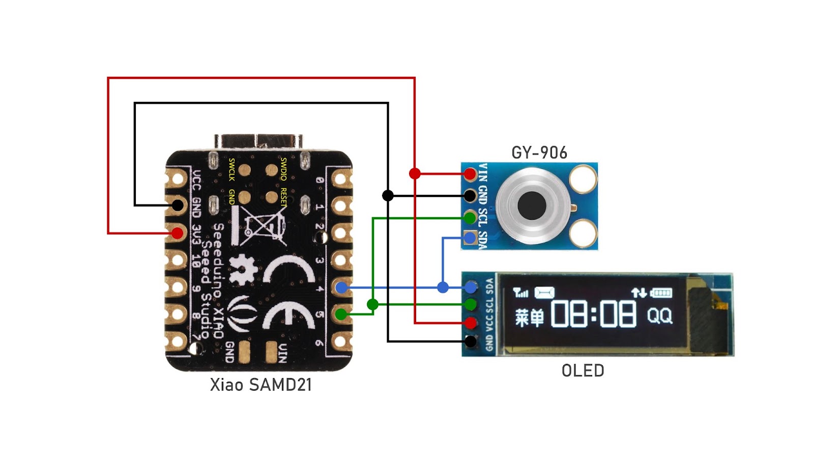
It is a simple circuit
- D4 of xiao to SDA of OLED and GY-906
- D5 of xiao to SCL of OLED and GY-906
- 3v3 of xiao to VCC of OLED AND GY-906
- GND of xiao to GND of OLED and GY-906
Step 7: Assembly and Wiring
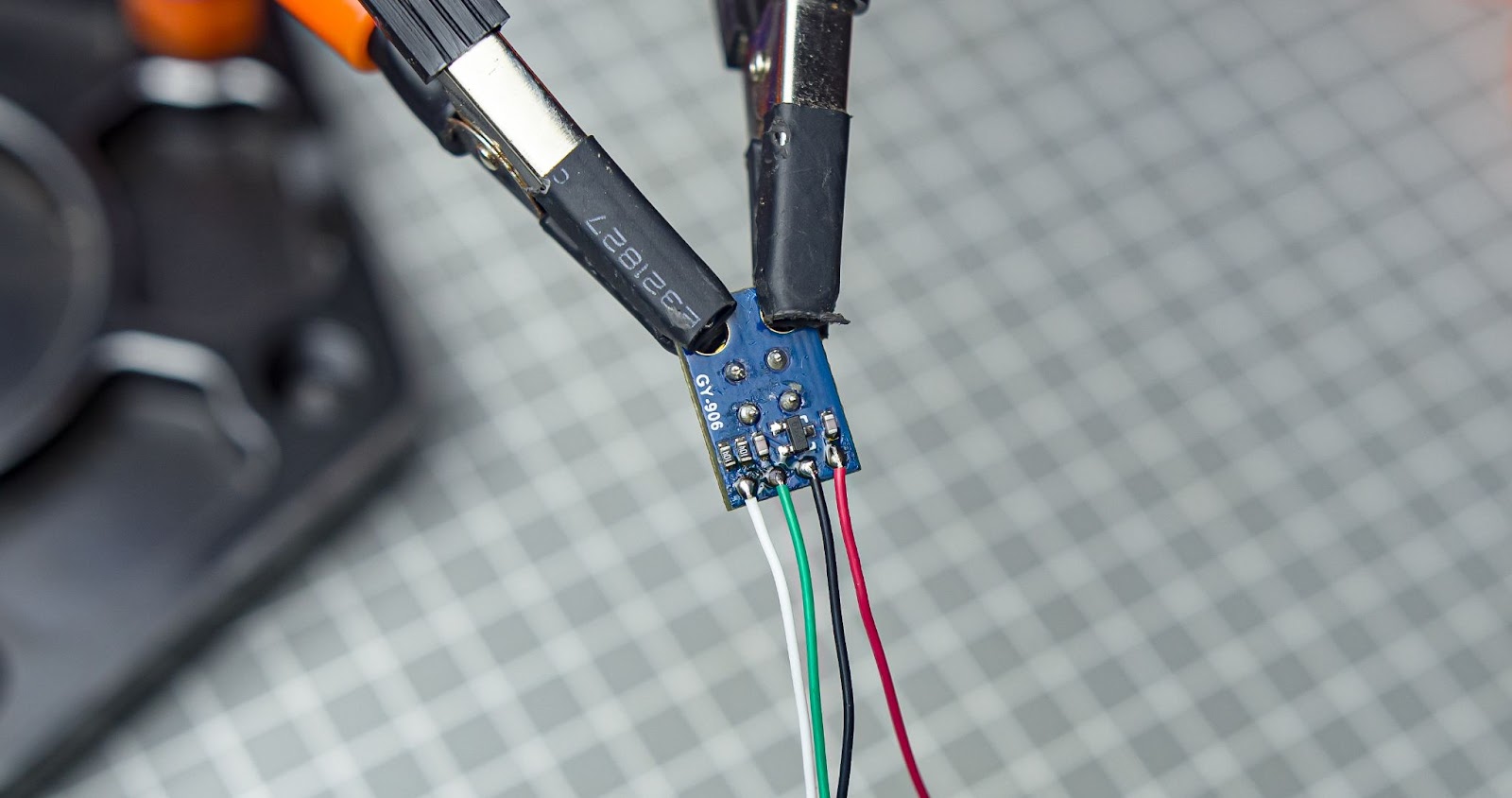
We can start with the sensor mount Assembly
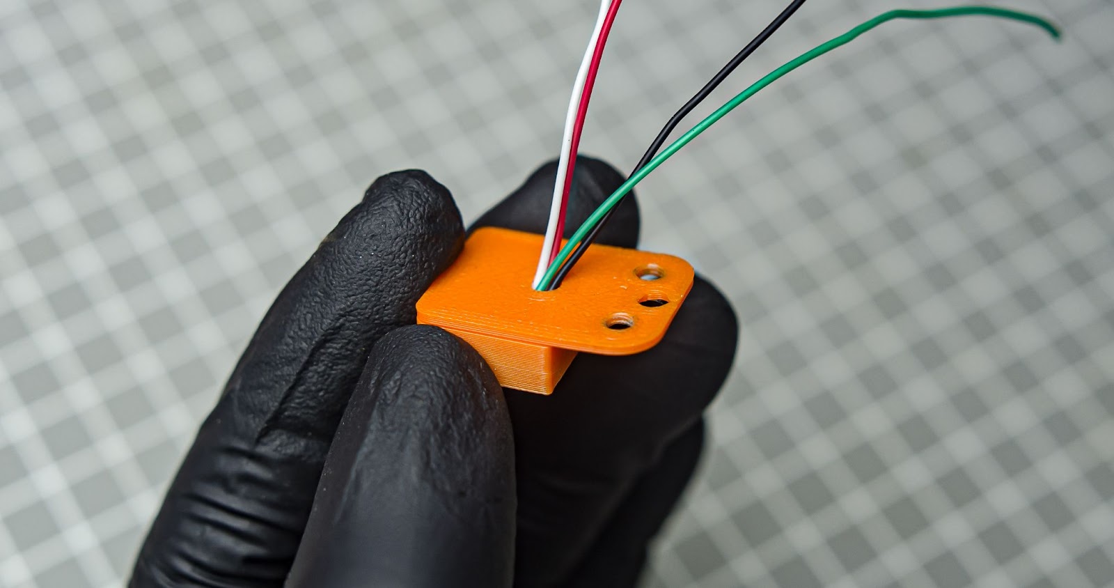
Step 1
Solder four 8cm wires into the GY-906 `
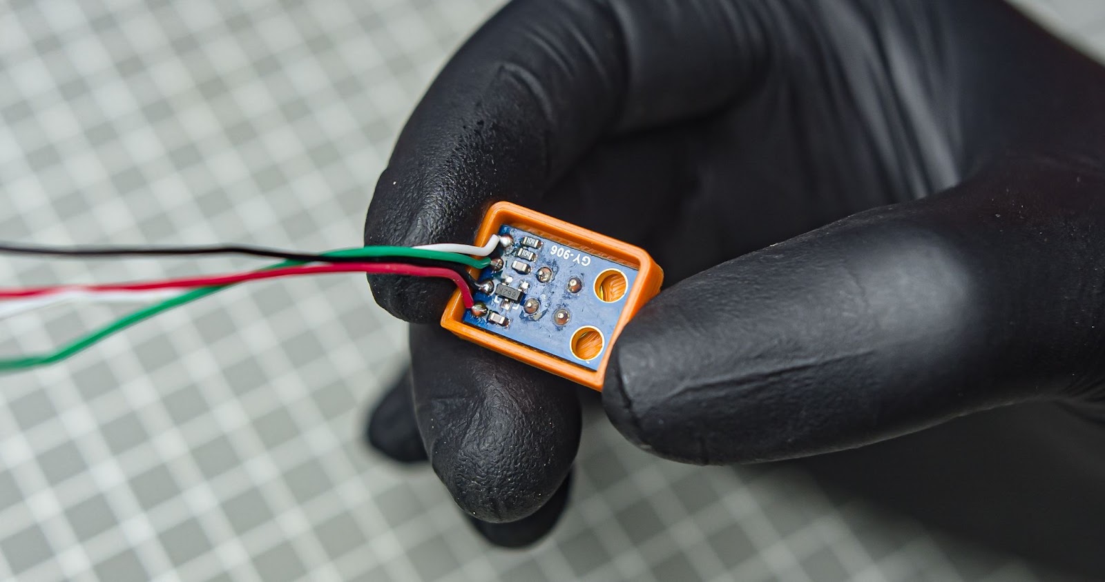
Step 2
Push in the GY-906 into the 3d print
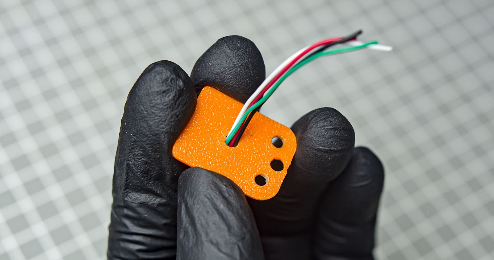
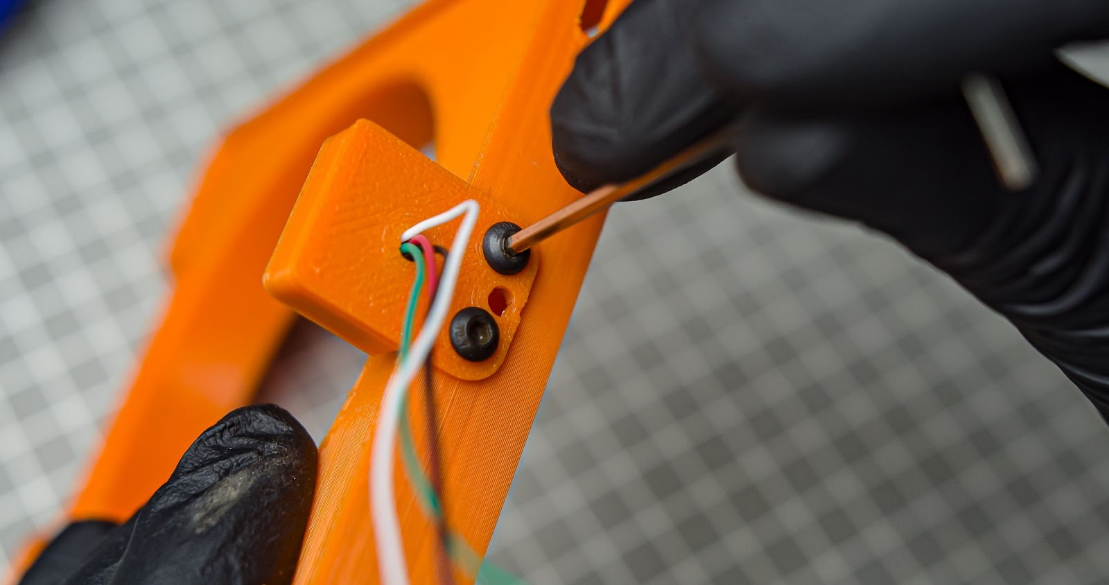
Step 3
Run the wires through the hole in the mount back cover
Step 4
Snap in the back cover
Step 5
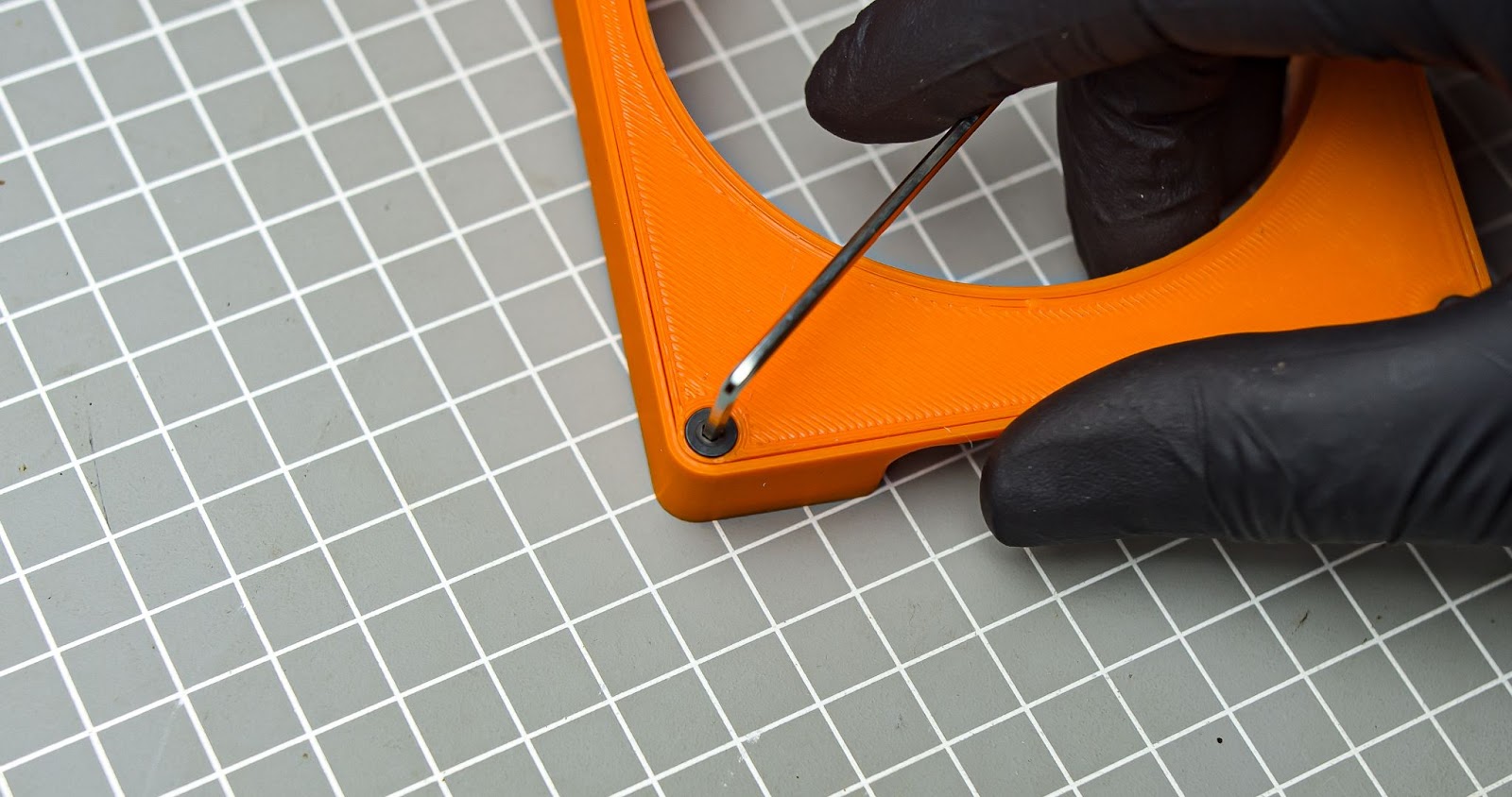
Screw in sensor mount with two M3 10mm screw
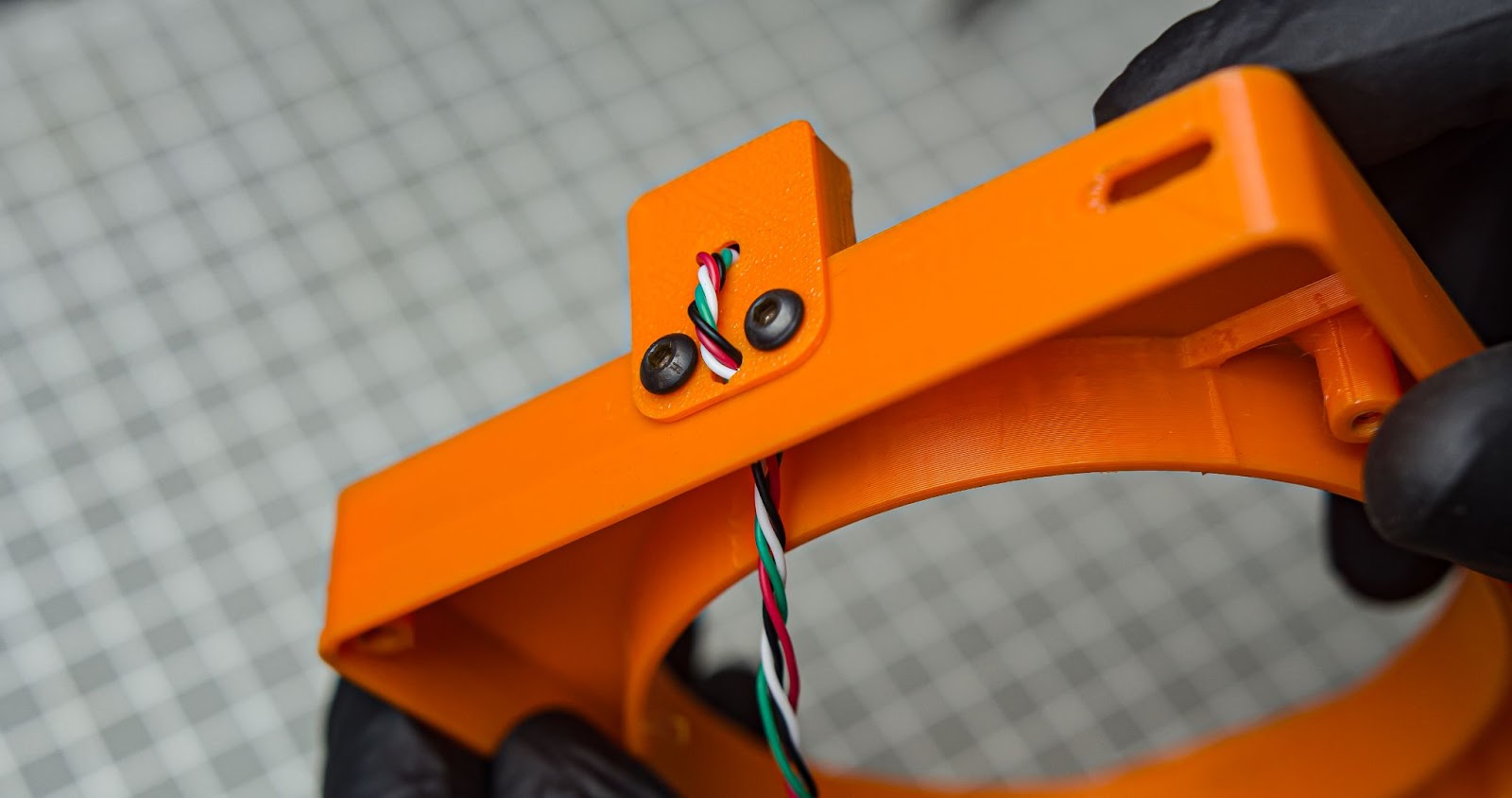
Step 6
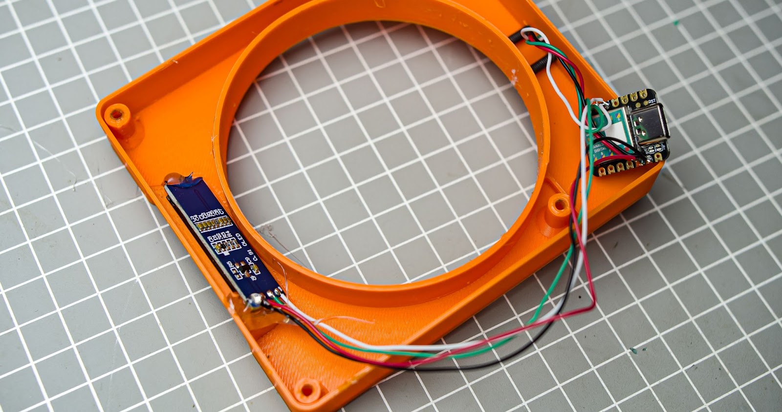
Run the sensor wires through the centre hole into the main body. Twist the wires a little bit
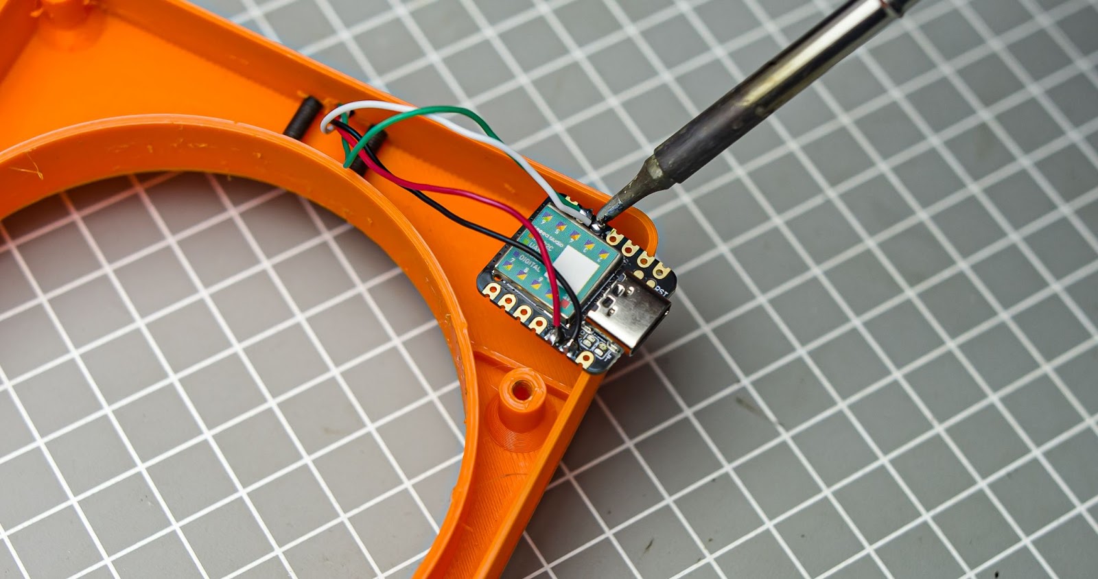
Step 7
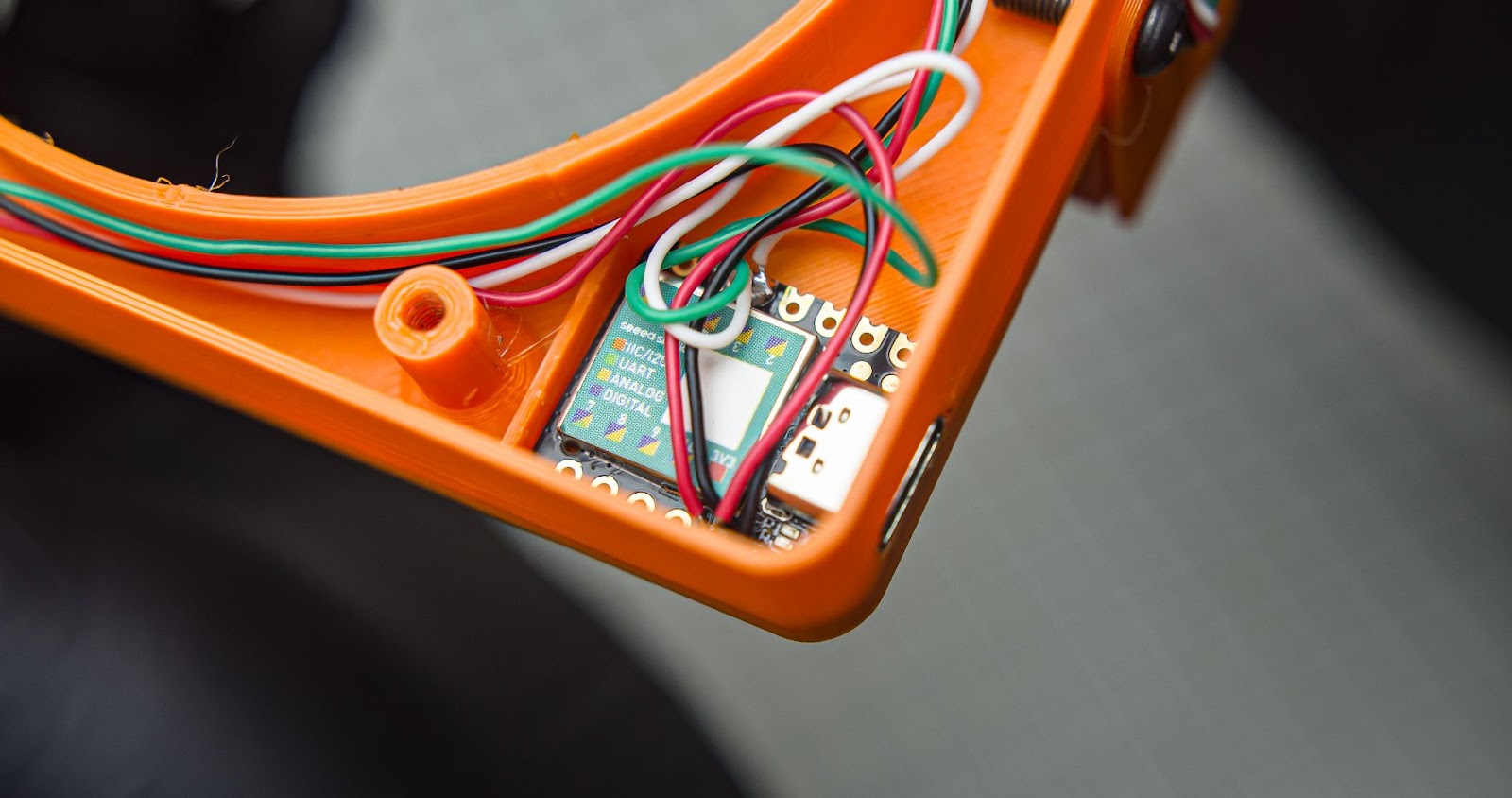
Solder sensor wires into Xiao
Step 8
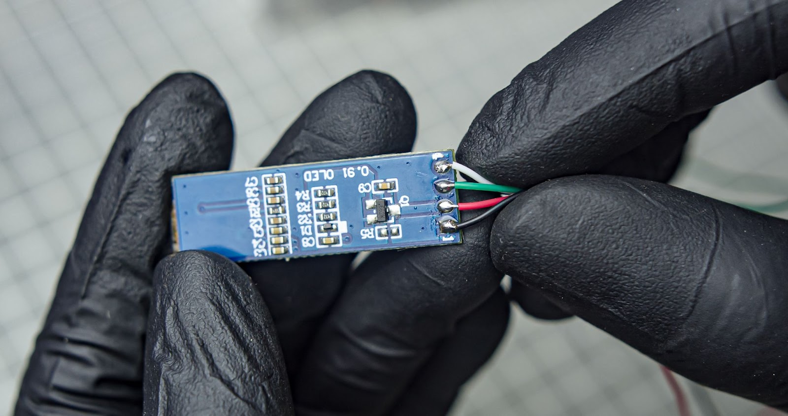
To connect the OLED terminals, you need to solder four wires with a length of 14cm each.
Step 9
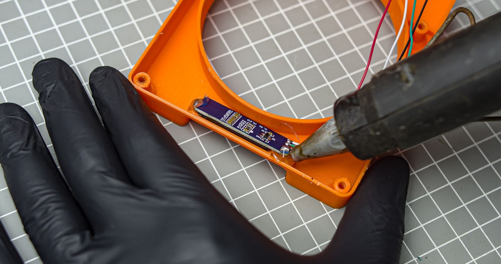
Align the OLED display with the 3D print's viewing window and glue it in place.
Step 10
solder the wires of the OLED into the Xiao.
Step 11
Insert the xiao into the 3D print, aligning it with the opening for the USB-C port. Secure it in place with glue if necessary.
Step 12
Attach the 3D-printed back plate by screwing it in with four M3*10mm screws.
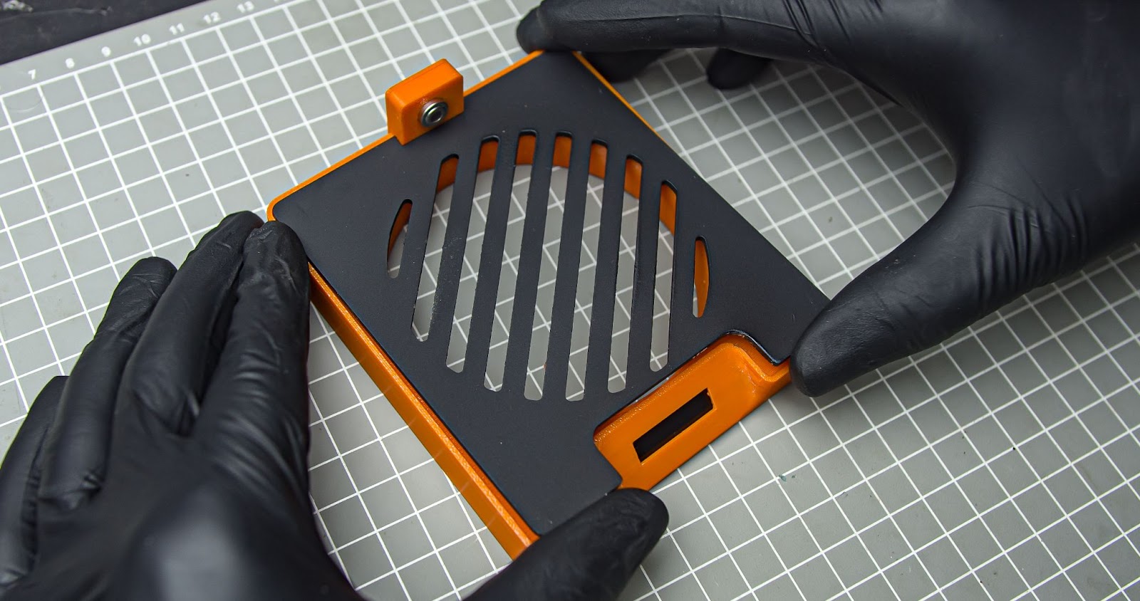
Step 13
Slide in the top aluminium plate
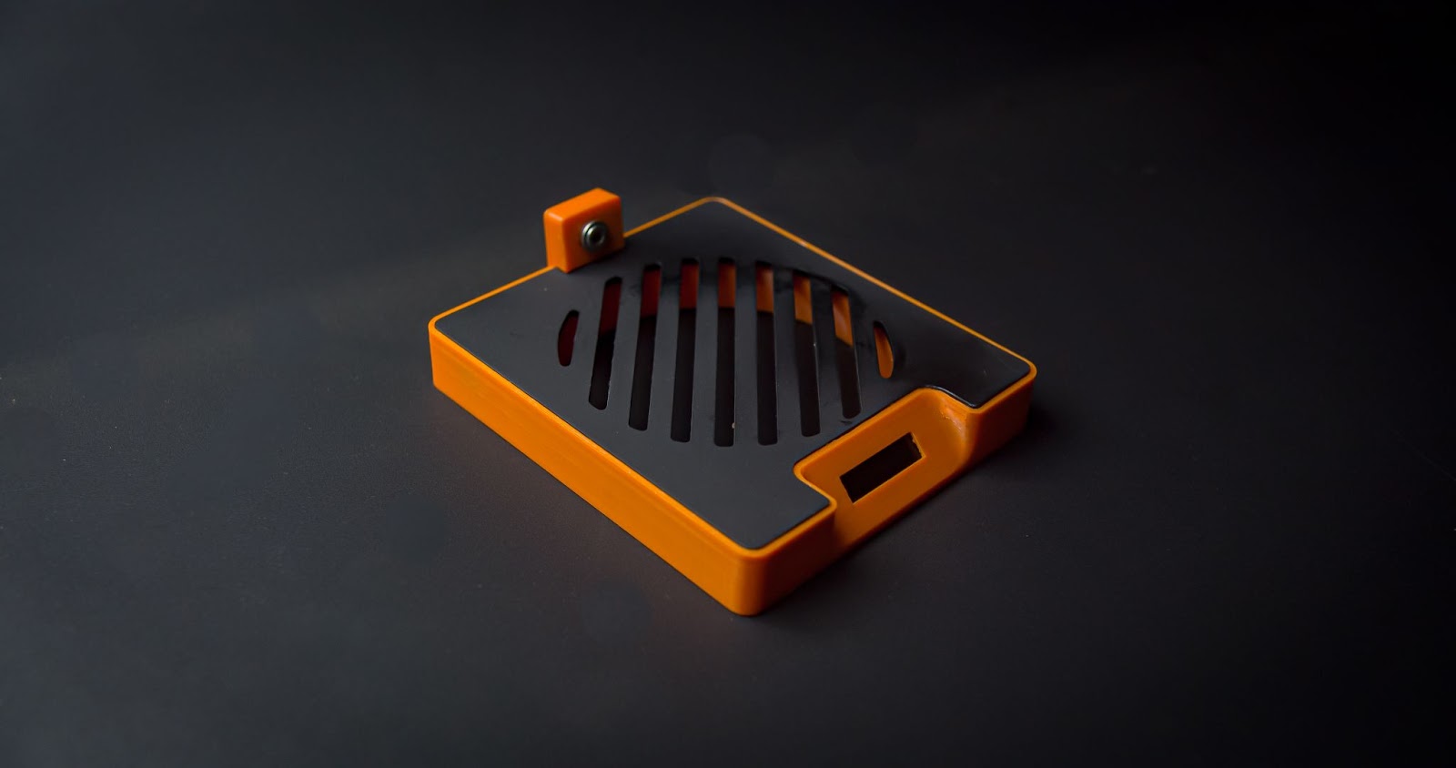
We just completed the assembly . we can power this with a USB cable paired with a phone charger
Step 8: Final Thought

"I hope it is a useful full project. also, more likely l love that I can design something that looks good. I am so happy to find out how the aluminium and 3d print can come together. You can customize the temperature range on the code easily. Also, it will only work with cups that have good thermal conductivity.I think it will look good on my dusk "

Grand Prize in the
Stay Warm Contest


