

Introduction: Tools, Tool Holders, and Offsets


The HAAS mill offers Library tools as well as Custom tools, let's go over the difference:
Library tools
- These tools are stored next to the mill and correspond to the Pier 9 Haas Mill Tool Library that you imported into your CAM software.
- Each tool is engraved with a number that corresponds to its number in the CAM software, from 101-175.
- These tools are loaded into tool holders by Shop Staff.
- The mill knows how long these tools are, so you will not need to measure them for length.
Custom tools
- These are the tools in your CAM program that are not in the library, such as drill bits.
- Custom tools do not have a default number in the CAM software. You will assign custom tools numbers 1-99, in the chronological order that they are used.
- You need to insert them into the tool holders.
- The mill does not know the tool length, so you’ll need to measure each custom tool in a later step.
Step 1: Insert Tools Into the Holders
There are two kinds of tool holders: drill chucks and collets. Both kinds should be held in the tool vise on the front of the mill while preparing custom tools.

Drill chucks
- Only use for holding drill bits.
- Tighten by applying force clockwise with the correct wrench for the chuck.

Collets & tool holders
- Use a collet that is the same size as the shank of the cutting tool.
- Snap the collet into the cap.
- Screw the cap onto the collet a few turns.
- Insert the cutter as deep as possible.
- Grip the shank, not the flutes.
- Tighten the cap with the wrench.
For staging the holders, iIn the order listed in your Setup Sheet, set the tools in the storage rack on the front of the mill.
Step 2: Tool Length
Check the length of the custom tools
In the CAM software, the library tools and tool holders are modeled. The software will detect a collision involving the holder.
The holders for custom tools are not modeled, and collision checking does not happen in software. You need to check for collisions manually.
If you set your Work Coordinate System (WCS) to the top of the stock in your CAM setup, the Minimum Z entry in your Setup Sheet will show how deep the tool will go into the material.
- Look at the Minimum Z entries in your Setup Sheet for each custom tool.
- This is the deepest point that the tool will go into the stock.
- Measure the amount of tool sticking out of the tool holder.
- This is called the approximate tool length.
- The approximate tool length must be larger than Minimum Z

Step 3: Pocket Tool Table
INSPECT THE POCKET TOOL TABLE AND CAROUSEL
Pocket Tool Table and Carousel
- The Pocket Tool Table (PTT) is a list of all tools inside the machine. It shows their location, in either a pocket or in the spindle.
- A pocket is a location in the carousel, which holds the tool when not in use. There are 24 pockets in the carousel.
- You must check that the PTT and the carousel are empty before starting. You are checking the last person’s work.
- The probe (tool #100) should never be removed.

Check the Pocket Tool Table
- Close the doors.
- Press MDI DNC. (mode keys)
- Press CURNT COMDS. (display keys)
- Press PAGE UP or PAGE DOWN (cursor keys) to navigate to the PTT.
- Check that all the tool entries, except the probe tool, are set to 0 (empty).
Reading the Pocket Tool Table
- Zero means no tool is in a pocket.
- The active pocket has an asterisk.
- Active means it's the pocket at the bottom of the carousel.
- Tool 100 is the probe.
- The yellow bar means that you have selected that pocket.
- H or L indicates a heavy or large tool.

Heavy or Large tools
- Heavy (or fragile, like the probe) tools are changed at a reduced speed.
- Enter H WRITE/ENTER to assign the tool to the pocket. Tools over 4 pounds are considered heavy.
- All bottom drawer tools (#161-175) are heavy.
Large tools require an empty space on either side in the carousel.
- Enter L WRITE/ENTER to assign the tool to the pocket.
- Tools over 3" in diameter are large.
To clear the label, enter Space WRITE/ENTER.
Step 4: Carousel

Visually check the Carousel
You must check that the carousel matches the pocket tool table, because there is no way for the mill to know if they are in sync.
Visually verify that the carousel is empty before inserting tools. Putting a tool into an occupied space will break the tool, or worse.
Only half of the carousel can be seen at once. Check the visible half, then rotate the carousel to check the other half.
- Visually check the carousel to see if any tools other than the probe are visible.
- Look at the Pocket Tool Table and find the active pocket.
- To rotate the carousel 12 positions, add 12 to the active pocket number.
- If the answer is larger than 24, subtract 12 instead.
- Enter P[pocket number] ATC-FWD. Check the carousel again after it rotates.
Example: pocket 3 is active
- 3+12=15
- Enter: P15 ATC-FWD

Step 5: Inserting Tools
INSTALL TOOLS INTO THE MACHINE
Open the Pocket Tool Table
- Press MDI DNC (mode keys)
- Press CURNT COMDS (display keys)
- Press PAGE UP or PAGE DOWN (cursor keys)
Use your Setup Sheets to help insert the tools.
- Use the cursor keys to highlight an empty pocket.
- Enter [tool number] WRITE/ENTER.
- Press RESET.
- Check that the doors are closed.
- Press T[tool number] ATC-FWD.
- The machine will perform a tool change.
- Open the door.
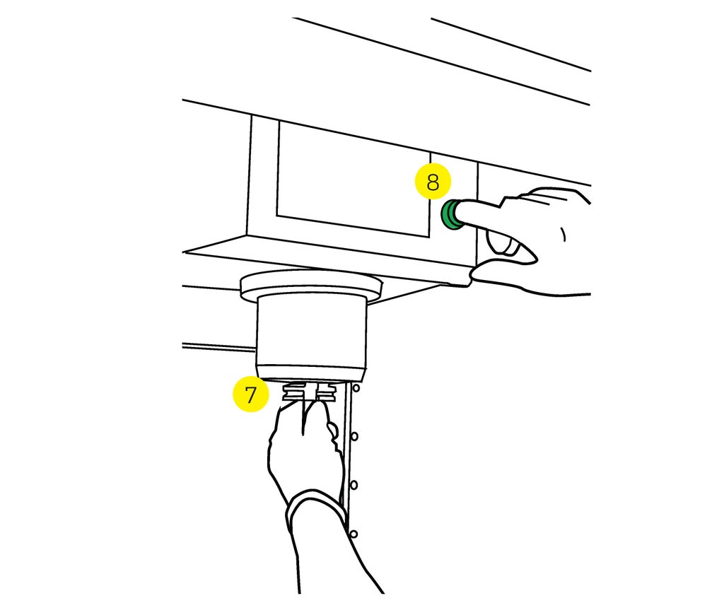
- Place the tool into the spindle.
- Align the notches in the holder to the tabs on the spindle.
- Press the tool release button.
- Close the door.
Repeat these steps for each tool.

Example - Install tool #123:
- Select an empty pocket. You selected pocket 2, highlighted in yellow.
- 123 WRITE/ENTER
- You just told the machine that tool 123 is in pocket 2.
- RESET
- T123 ATC-FWD
- The mill performed a tool change from pocket 2 (empty) into the spindle.
- There's no tool in the spindle, even though it's listed in the PTT.
- Open the door and put tool 123 into the spindle.
- The PTT and the machine are now in sync.
Step 6: Set the Tool Offsets
Tool Offsets are the length and diameter of the tools. Shop staff measures offsets for tool library tools with the Speroni optical system. The tool offsets are stored in the Library Offset File.
- You need to import the Library Offset File each time you use the mill.
- You do not need to measure library tools.
- Measure the custom tools after installing them in the mill.
Import the Library Offset File
- Press LIST PROG.
- Press CANCEL to go up a level.
- Use the cursor keys to navigate to the NET SHARE tab.
- Press WRITE/ENTER.
- Use the cursor keys to select the Haas_VF2.nc file.
- Press F2.
- Select Copy to Memory.
- Press WRITE/ENTER.
- Press Y when prompted to confirm.
- Disk Abort means that the machine has been updated with the latest tool library offsets.
Custom Tool Offsets
Follow these steps to measure the tool offset for custom tools.
1. Press MDI DNC.
2. Press T[tool number] ATC-FWD to perform a tool change.
3. Press OFFSET (display section).
- The OFFSET button will toggle between Work Offset & Tool Offset.
- Be sure that Tool Offset is selected (the active window is white).
4. Use a tape measure to measure the length of the tool.
- Measure from the tip of the tool to the base of the spindle.
- Be within 1/4".
5. Use the cursor keys to navigate to the Approximate Length column.
- Enter the tool length.
- Press F1 to set the value.
Note: Whole numbers need a decimal point, or they will be entered as ten-thousands of an inch. (8 = 0.0008 and 8. = 8)
6. Navigate to the Flutes field.
- Enter the number of flutes.
- Press F1.
7. Navigate to the Tool Type field.
- Select the tool type.
- Press F1.
If the tool is a custom end mill, follow the steps in the *notes below; go to step 8 when entering drill bits or taps.
8. Navigate to the Probe Type field.
- For custom end mills, use probe type 1.
- For drills or taps, use probe type 2.
9. Press [probe type number] and WRITE/ENTER.
10. Close the doors.
Press TOOL OFFSET MEASUR (near RESET).
Press CYCLE START
Navigate to the Geometry (length) field.
Compare this number to your approximate measurement.
If there is a large difference, stop and investigate.
Repeat these steps for each custom tool.
*if the tool is a custom endmill, follow these steps:
1. Navigate to the i column.
- Enter the approximate diameter of the tool.
- Press F1.
2. Navigate to the Edge Measure Height column.
- This is only used on end mills that don't have their full diameter at the bottom, like ball end mills.
- Enter the distance from the bottom of the of the tool that the measurement should be taken.
- Press F1.
3. Go to step 8 above.
Step 7: Custom Tool Offsets

Measure the custom tools.
Follow these steps to measure the tool offset for custom tools.
1. Press MDI DNC.
2. Press T[tool number] ATC-FWD to perform a tool change.
3. Press OFFSET (display section).
- The OFFSET button will toggle between Work Offset & Tool Offset.
- Be sure that Tool Offset is selected (the active window is white).
4. Use a tape measure to measure the length of the tool.
- Measure from the tip of the tool to the base of the spindle.
- Be within 1/4".
5. Use the cursor keys to navigate to the Approximate Length column.
- Enter the tool length.
- Press F1 to set the value.
Note: Whole numbers need a decimal point, or they will be entered as ten-thousands of an inch. (8 = 0.0008 and 8. = 8)
6. Navigate to the Flutes field.
- Enter the number of flutes.
- Press F1.
7. Navigate to the Tool Type field.
- Select the tool type.
- Press F1.
*If the tool is a custom end mill, you should now follow steps 1-3 below;
or skip directly to step 8 when entering drill bits or taps.
- Navigate to the Approximate Diameter column.
- Enter the approximate diameter of the tool.
- Press F1.
- Navigate to the Edge Measure Height column.
- This is only used on end mills that don't have their full diameter at the bottom, like ball end mills.
- Enter the distance from the bottom of the of the tool that the measurement should be taken.
- Press F1.
- Go to step 8.
8. Navigate to the Probe Type field.
- For custom end mills, use probe type 1.
- For drills or taps, use probe type 2.
9. Press [probe type number] and WRITE/ENTER.
10. Close the doors.
11. Press TOOL OFFSET MEASUR (near RESET).
12. Press CYCLE START
13. Navigate to the Geometry (length) field.
- Compare this number to your approximate measurement.
- If there is a large difference, stop and investigate.
Repeat these steps for each custom tool.


