

Introduction: Ultrasonic Garage Parking Sensor LED Stop Light


I recently added a wood rack to my garage, which unfortunately reduced the car parking depth. I now have to pull up to a few inches of the rack to allow adequate space behind the car to access the rest of my garage. Clearly, it would be nice to have something that helps reliably park very close to the wood rack without actually running into it.
I know it would be easiest to attach a tennis ball to a string and hang it from my garage ceiling in front of my windshield. Clearly, not a 21st century solution! Why do something simple when you can use an ultrasonic sensor, a micro controller, LEDs, and a 3D printed housing?
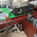
I tested the measurement range of a readily available (and inexpensive!) ultrasonic sensor and found it should work well for this application. So I designed the Garage Parking Sensor to look like a stop light using a HC-SR04 ultrasonic sensor, an Arduino Nano and Expansion Shield, and three sets of LED, green, yellow, and red. The Nano software is designed around the SR04 code library with some additions, discussed in the software section. The result is a wall-mounted sensor that transitions from green LEDs on from 8 feet away, to yellow LEDs at about two feet, then red and yellow LEDs at about 12 inches, and finally red LEDs at about 4 inches from the the desired position. The final assembly is shown in the picture.
The HC-SR04 Ultrasonic Module provides real time distance to an object using an Arduino Nano. A potentiometer is used to tune when the red LEDs are turned on, so you can park 30 inches from the wall mounted sensor, which is 4 exactly 4 inches from the wood rack. I decided it was simpler (and more fun) to develop a custom PWB for the LEDs and drive circuits (see schematic below). All the Gerber files for the custom PWB (see note Step 1), and the arduino code is provided below. Of course, the sensor has to be housed in an enclosure, which was designed using Fusion 360 and 3D printed. The .stl files are also included below.
The whole project can be built for under $35, including purchasing the custom circuit board. (You might have to spend more to buy multiples of parts to get the best price, but you'll have lots of parts left over for your next project!)
Supplies


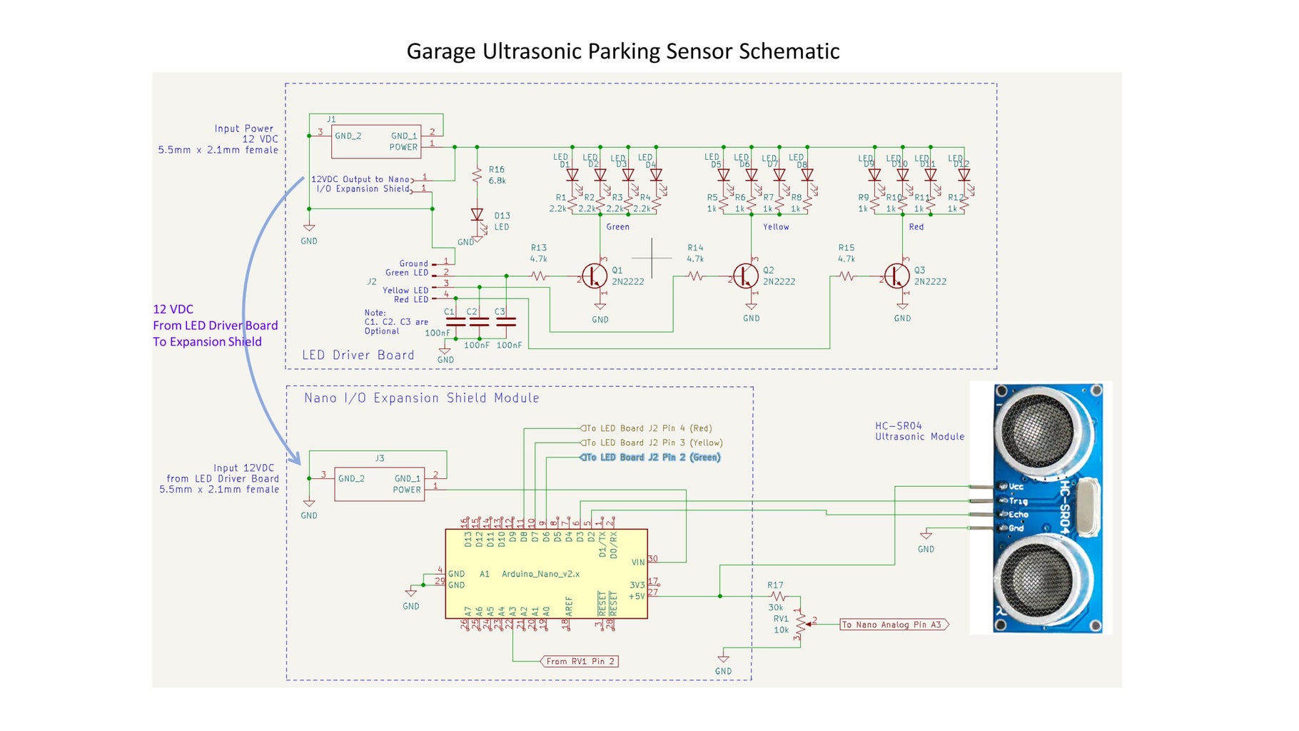
The Ultrasonic Garage Stop Light parts list is provided above. Essentially all of the parts are available from Amazon, but you may find lower prices if you look elsewhere. If you are an arduino hobbiest, you probably already have many of the parts lying around.
In addition to the specific parts needed for the project, access to a 3D printer is needed, some 3D printer filament (i.e. PLA), a soldering iron and solder, and a variety of hand tools.
Step 1: Order the Printed Circuit Board

Although the LED driver board could be hand wired on a proto board, a custom printed circuit board was developed (using KiCad). The schematic of the PWB is shown in the figure. All the Gerber files needed for this board are included below.
Simply zip them into a .zip file and drag and drop them into your favorite custom PWB web site. I have had very good success with several custom boards using JLCPCB (https://jlcpcb.com). Once the zipped up Gerber files have been dropped into the "Add gerber file" window on the web site, the front and back sides of the boards magically show up in a new window. Simply follow the on-line instructions. You can modify some of the board options, but all the default setting seem to work fine. You get 5 raw PWBs for $2!
(UPDATE: I was not able to upload Gerber files for this PWB: "file type not supported". Please send me a note in the comment section at the bottom of this Instructable, and I will email you the zipped up Gerber files.)
Since I'm retired, I'm in no hurry for anything anymore, so I went with the least expensive shipping option. Sure enough, about 12 days later you will receive a small box with five high quality custom boards ready for assembly, and all for under $10! Amazing!
I recommend using the PCB because the alignment between the LEDs on the PWB and the 3D printed front housing will be exact. Besides, if you haven't purchased a custom PWB yet, it's a good experience.
Step 2: 3D Print Sensor Housing


The next step is to print the housing component and spacers. Start with the "Front Body V5" as it will be used to help align the LEDs on the LED driver PWB. Note that the orientation of the parts on the print bed are shown in the figures.
NOTE: The housing was originally designed in inches. Your slicer may assume they are in mm which makes the parts very small. Try increasing the scale factor to 2540%, or a factor of 25.4. As of 3/14/23, the .stl files have all been modified to be in mm.
The Front Body part should be printed with the outside face up. (The attached .stl files are all in the recommended orientation.) This will require the use of supports in the ultrasonic sensor cavity. Once complete, remove the supports using needle nose pliers and an exacto knife. Note also that there are also 6 pilot holes for screws that hold the two chassis parts together. These should be cleared out with the tip of an exacto knife.
The Side Shell part is printed with the back side (with the mounting tabs) upwards. This also requires supports, which are very easy to remove. (Thus, the two housing components mating surfaces are both printed against the print bed.) Note that the two cross braces must be removed with a small saw and filed smooth.(I thought they would help stabilize the print, but I don't think they are needed.)
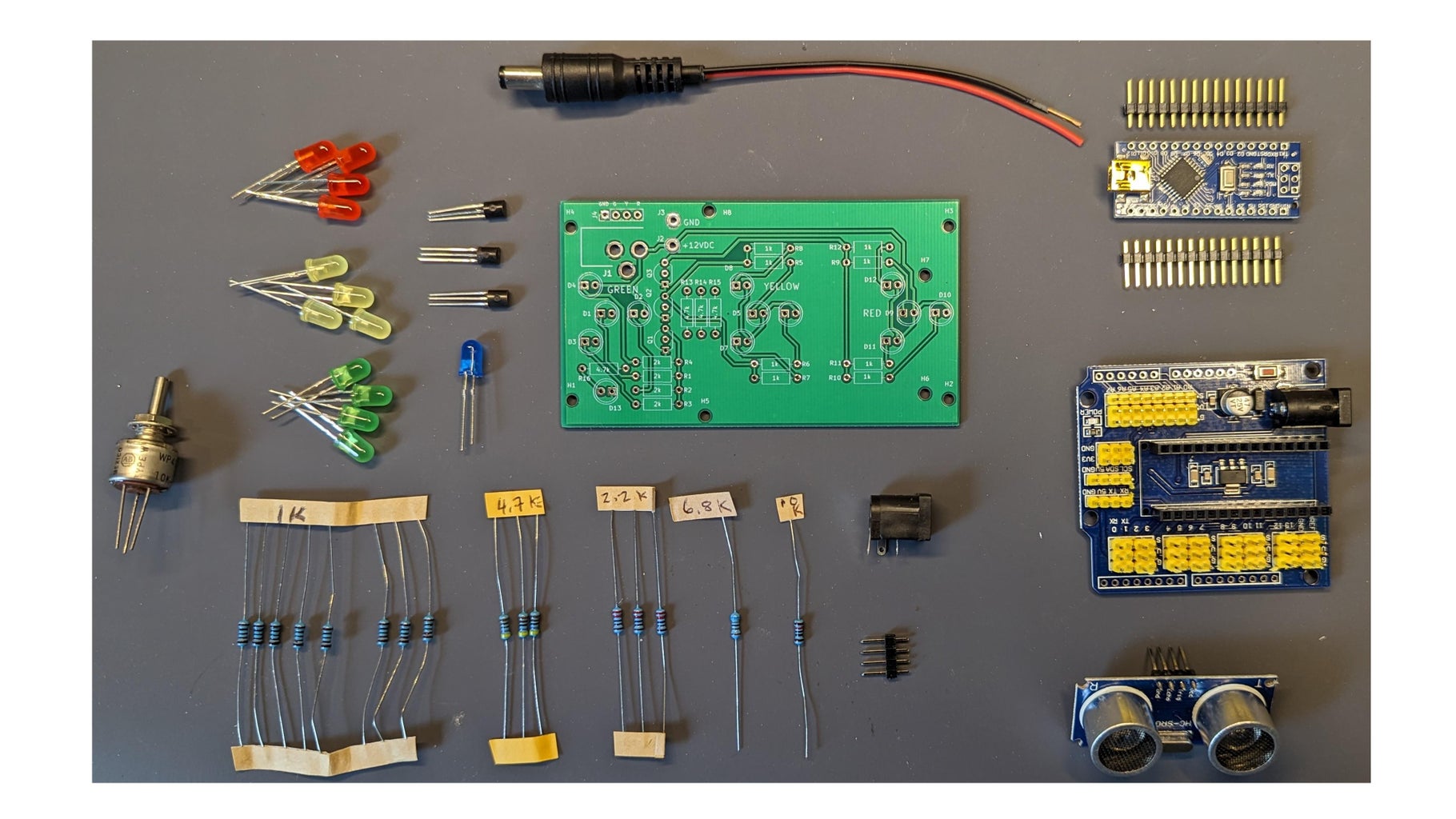
Finally, print the 4 spacers used between the LED Drive circuit board and the Nano Expansion Shield, the potentiometer knob, and the backing plate.
I use PrusaSlicer-2.5.0 to slice the .stl files, and a Prusa i3MK2.5S for printing. PLA is used for all parts, sliced with a 0.2mm layer spacing with 40% infill. I also use 3 perimeter shells to improve strength. Other rigid filaments could also be used. The particular filament I used is "Granite 1" from Hatchbox (I like the way it looks!) for the housing and a black filament for the back, potentiometer knob, and spacers.


Step 3: Electronic Assembly


The schematic of the complete ultrasonic sensor is shown in the figure. Note that there are two major assemblies, the LED drive PWB, and the Arduino Nano Expansion Shield (see parts list). After PWB assembly, the two boards are screwed together with 3D printed spacers, and mounted onto the back of the front panel.
The Ultrasonic Garage Stop Light consumes less than 100mA at 12VDC. When all LEDs are off, it consumes about 25 mA (about 0.3 watts)
The parts needed for the PWB are shown in the next photograph.
LED Driver PWB Assembly
The first step is to install the three sets of colored LED onto the LED Driver PWB. Use the PWB silkscreen text to locate the parts. Make sure you install the LEDs onto the BACK of the board, making sure the LEDs are installed correctly (anode - longer lead - goes into the hole with the round solder pad, and cathod - shorter lead - goes into the square solder pad). Do not solder. See the photo.
Once all the LEDs are in place, align the board with the back of the front housing (green LEDs closest to the ultrasonic sensor) and press the board firmly downwards until all the LEDs poke through the front housing. Once all the LEDs are pushed through the holes, solder the leads on the front of the PWB. Trim the leads flush with the front side of the board.
Next, install the resistors (bend te leads, insert, solder, and trim). Note that the series resistors for the red and yellow LEDs are all 1k (R5-R12), whereas the resistors for the green LEDs (R1-R4) are 2k (any value between 2-3k is fine). For a given drive current, the green LEDs are quite a bit brighter than yellow and red ones, so a larger series resistor helps to balance the brightness by lowering the current. Install the three series transistor base resistors (R13-R15), and finally R16 (series resistor for the blue LED power on indicator).
Solder the three NPN transistors into the PWB making sure the flat surface corresponds to the silkscreen, and trim off the protruding leads. These transistors simply act as switches to turn on the LEDs when a base signal is applied from the Arduino. Any general purpose NPN transistor should work fine.
Finally, solder the 4 pin male header onto the board, the blue LED, the female DC power jack, and finally the power pigtail. Trim the power pigtail length to abou 4 inches. (I stripped off the heavy insulating casing around the two power wires since it was very stiff.)
At this point, your PWB is finished, and should look similar to the PWB in the pictures. If you want to test the board, plug 12VDC into the DC power jack, ideally from a bench power supply. The blue LED should light up, but not R, Y, or G LEDs. To test the LEDs, connect a ~5K resistor to the same +12volt supply and touch the other end of the resistor to the R, Y, or G male pin headers. This should cause the corresponding set of LEDs to illuminate.
Expansion Shield Assembly/Comment
Solder the headers onto the Arduino Nano, if the Nano doesn't already come with headers attached.
A note on using knock-off Arduino Nano parts. I got a set of 3 Chinese knock-offs from Amazon at a good price (specifically, the "ELEGOO Nano Board CH 340/ATmega+328P Without USB Cable, Compatible with Arduino Nano V3.0"). You may need to download the USB driver for these parts in order to programm the parts if you haven't already done so. Specific information about the driver is located here: https://learn.sparkfun.com/tutorials/how-to-install-ch340-drivers/all
A word of caution: it is best to work on an antistatic mat when working with these parts. I have had many failures over the past few years, and unfortunately, I'm averaging needing over 2 Nano parts per project. I'm not sure how it happens, but I think the USB interface fails, maybe from a small static discharge. In some cases, parts have failed after the part was installed and programmed so it still works in the circuit, you just can't update the software. Hence, I suspect the CH340 USB interface chip. (Note: it is still cheaper to use 3 Chinese knockoffs and have two fail than to buy one genuine Arduino Nano. I bet the genuine Arduinos probably have antistatic protection built in and won't fail as often.)
Final Board Set Assembly
Once the Nano is installed into the Expansion Shield, the two boards can be mated together. Use four 2-56 screws, the 3D printed spacers, and 4 2-56 nuts. The screw must be inserted from the LED side of the LED driver PWB, through a 3D printed spacer, and through the Expansion shield. Thread on a 2-56 nut and tighten. The attached photograph shows the final stack.
Install the HC-SR04
First, carefully bend the four pins of the HC-SR04 so they are nearly perpendicular to the board. Insert it into the front housing from the back such that the four pins are toward the center of the housing. Four stanoffs are designed into the housing to provide the correct spacing. Insert four black 0-80 screws from the front through the housing and HC-SR04, and secure with four 0-80 nuts. These small components are not easy to work with!
Install Board Assembly onto Front Housing
Align the PWB LEDs into the back of the front housing and press the boad stack down as far as possible to fully seat the LEDs. Thread four black 2-56 1/2" screws through the front of the housing to the LED PCB and secure with 2-56 nuts. There are no spacers needed. Finally, plug the pigtail power lead from the PWB into the female receptacle on the Shield board, as shown in the figure.
Pot Assembly
Prepare three 2.5" breadboard jumper wires with a female connector on one side and a bare wire on the other. Solder one wire to the center wiper pin of the pot (red in the picture), and another to one end of the pot (green in the picture). Solder one end of the 30k resistor (R17 in the schematic) to the third breadboard jumper, and the other end of the resistor to the pot (white in the picture). You can cover the solder joint with heat shrink tubing if you want.
The resistor value really doesn't matter too much, so any resistor value between 10K and 50k will be fine. It simply affects the sensitivity of the pot for adjusting the threshold distance. A larger resistor value allows more precise distance settings. Set this assembly aside for Step 5.
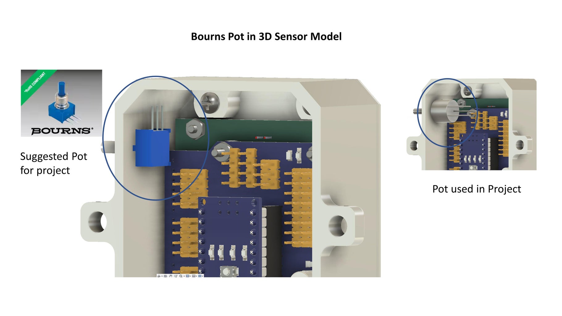
Full disclosure: I used a pot that I had around for this project. But a similar pot costs about $22, too much for this project in my opinion. So, I selected a pot from Digi-Key that should work in the space envelope for about $3.50. One of the figures shows the 3D model with both pots, a good indicator that the Digi-Key pot should work fine. Wire it up in a similar manner as described above.
Step 4: Wiring
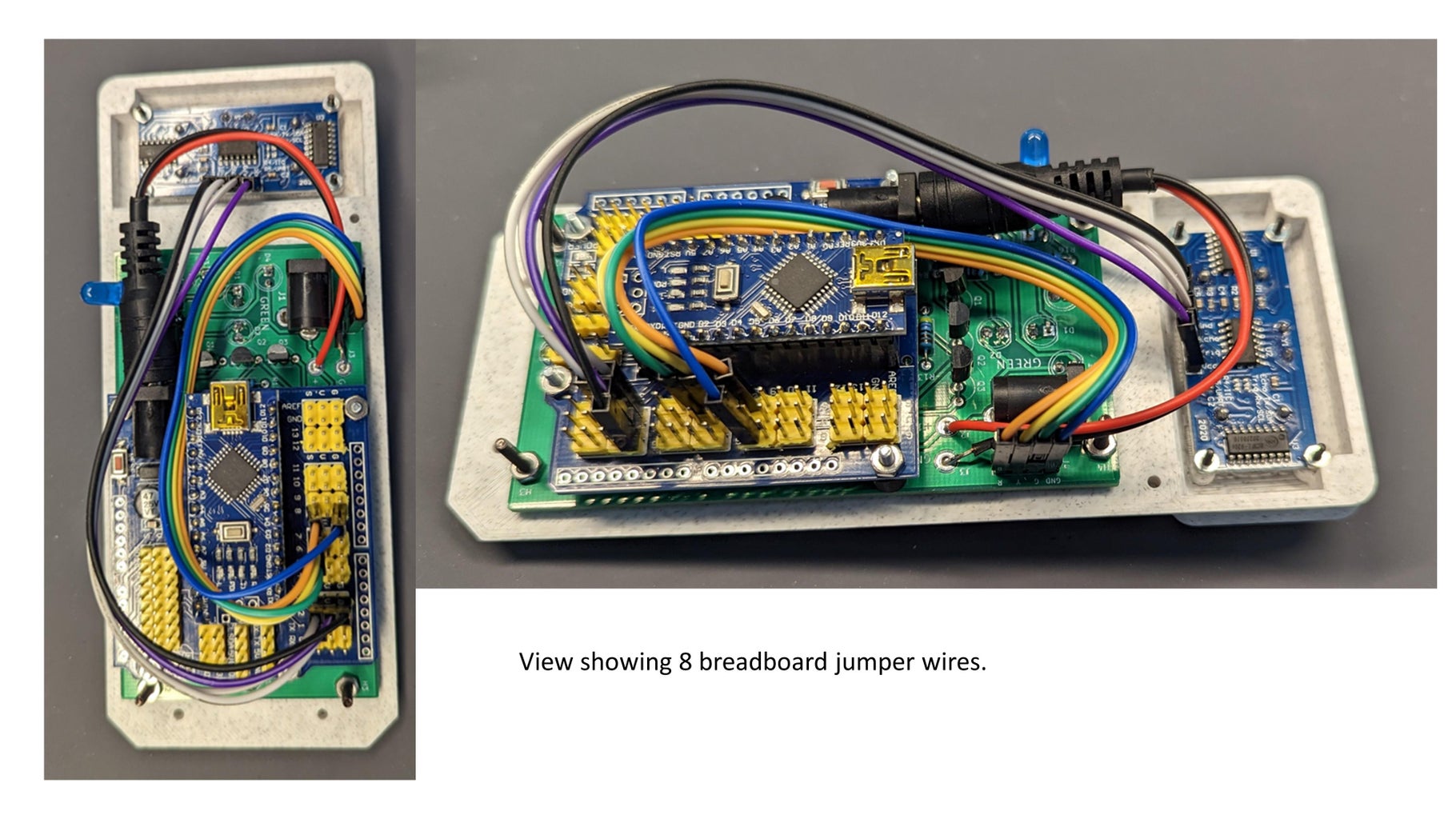
There are only 8 connections needed, four from the HC-SR04 to the Nano Shield, and four from the LED Driver PWB to the Nano Shield. See the photograph.
Peel off two sets of 4 wires each of female/female breadboard jumper wires. Connect up the HC-SR04 as follows:
- From HC-SR04 GND terminal to the male "G" (ground) connection adjacent to pin 3 on the Nano Shield.
- From the VCC terminal to to the "V" connection adjacent to pin 3 on the Nano Shield.
- From the Echo terminal to the "S" connection adjacent to pin 2.
- From the Trig terminal to the "S" connection adjacent to pin 3.
Note that all the "Gs" on the Nano Shield are connected together, as are all the "Vs", so you can pick other places to connect the voltage source and ground if you want.
Connect up the LED Drive PWB as follows:
- The GND pin on the PWB to a G pin near 8 on the Nano Shield.
- The "G" (green) pin on the PWB to the "S" pin next to pin 6 on the Shield.
- The "Y" pin on the PWB to the "S" pin next to pin 7 on the Shield.
- The "R" pin on the PWB to the "S" pin next to pin 8 on the Shield.
See the wire routing in the picture. The wires need to be bent at about 90 degrees at the female connector for best fit.
If you don't fully trust the integrity of breadboard wires in a project, you could solder all wires.
Step 5: Final Assembly


Install the potentiometer assembly from Step 3 into the side housing, and secure with the nut. The pot shown is the one I used for this project, not the one in the parts list, item 9 as discussed in Step 4.
Position the side housing over the front panel as shown in the picture. You might have to move some wires around. You will also have to move the blue LED to enable the side housing to fit. Once everything looks good, bend the blue LED to partially poke through the side housing hole.
Connect up the three leads from the Potentiometer assembly as follows:
- The end of the pot with the resistor connect to the "V" pin by pin A3;
- The other end of the pot connect to the ground "G" pin by A3;
- Connect the center pin, or wiper, to the "S" pin closest to A3.
Finally, install 6 #4 sheet metal screw (parts list item 18) into the 6 screw positions, and tighten down. If you have problems tightening the screws, check to make sure you removed any 3D printed supports left in the pilot holes. If your screws are too long, don't tighten them down as they will protrude through the front panel! Instead use a couple of washers to increase the screw spacing.
Step 6: Software Loading

Connect a USB cable from your PC to the mini USB socket on the Arduino Nano inserted in the Shield
The Parking Sensor Stop Light sofware is below. Upload the sketch like you would for any other Arduino project. (If you purchased a less expensive Chinese Nano you will probably need to upload custom USB interface software to your computer. You should be able to download the USB drivers here: https://www.elegoo.com/blogs/arduino-projects/elegoo-arduino-nano-board-ch340-usb-driver . You may have to play around with the loading to get it to work....I did. (I always start by trying to load the blink program with different blink durations until I know it is loading properly. Only then do I load the actual program.)
The Arduino code should work as is. (Note that the power from your computer will drive the Nano, but WILL NOT drive the LEDs. You need to use the 12VDC wall bug or a bench supply for the LEDs to operate.) The code is fairly simple and I've added comments to help explain what's going on. Also, I've commented out most of the troubleshooting code used to get it all to work. You can un-comment these lines and watch what's happening from a distance and time standpoint on a serial monitor.
Here is a summary of how the sensor responds, assuming the potentiometer is set for zero offset (up against a stop).
With no potentiometer offset:
- > 96" - all LEDs off
- Between 24" and 96" - Green LEDs on
- Between 12" and 24" - Yellow LEDs on
- Between 4" and 12" - Both Yellow and Red LEDs on
- Less than 4" - Red LEDs on
By adjusting the potentiometer, all these distanced can be shifted by about 35 inches. For example, depending on the pot setting, a vehicle at 25" from the sensor will turn the Red LEDs on.
Other characteristics of the sensor are:
- When power is applied, the blue LED should light up.
- When first powered up, the SW tests all the LEDs by flashing them on - off - on - off.
- Immediately after the LED test, depending on the distance to an object and the pot setting, some LEDs will light up
- After about 30 seconds, if there has been no chanage to the vehicle distance, all LEDs will turn off. LEDs will again turn on if movement is detected.
Once the Nano is loaded, you can test the Sensor to make sure everything works before mounting it to the wall of your garage. Apply 12VDC from the wall power bug (see parts list) to the power connector on the LED PWB. You should observe the LED flashing, and then one of the LED sets will be on steady state. Adjust the potentiometer to see its effects. Place your hand in front of the sensor and move it back and forth. The LED color should change. Finally, wait for ~30 seconds with a static background, and all LEDS should turn off.
Step 7: Installation


To prepare the sensor for installation, connect the male connector from the power supply bug to the female DC power jack located on the LED PWB. Route the power wire through the slot in the bottom of the housing. Position the cover over the back of the housing and push four #8 1.75" screws (sheet rock, deck, or wood screws) through the four mouting tabs and the corresponding mounting tabs on the cover. (The back cover is not otherwise fastened to the housing....maybe is should be.)
Once everything is ready, use the back cover as a template for where to drill pilot holes on the wall in front of where you want to locate the sensor. The unit should be mounted to a wall in front of your vehicle. It can be mounted off center as long as some part of the car is in front of the sensor. Screw the unit to the wall, and plug the power supply into an outlet or extension cord. It should turn on and start to operate.
To calibrate the sensor, park your car where you want it, and carefully adjust the potentiometer until only the red LEDs are on (it is sensitive). You should note that LEDs will transition from green, yellow, yellow-red and finally red. Adjust the pot just until the red light just goes on. This should result in a distance of around 4 inches.
Step 8: Modifications / Improvements
To really minimize power consumption, I connected the Garage LED Parking Sensor power to my garage door opener light socket using a light plug-to-socket adapter. (The adapater + a low porfile LED light still fits in the garage door opener!) So, the sensor is only powered when the light from the garage door opener is on. Generally, the garage opener lights automatically turn off after a few minutes. So, when you open your garage door to park, the sensor is powered, but turns off after a few minutes.
When the prototype unit was installed in my garage I noticed that the LEDs when nominally off would dimly flicker. When investigating the problem with an oscilloscope, I found that there is noise on the signals from the Nano to the LED Driver PWB (the bases of the transistors) with enough amplitude to turn on the transistors for a very short time, hence the flicker. Each of the three signals (R, Y, G) all had the same noise characteristics. Not sure where the noise comes from, but probably from the Nano. To eliminate the issue, I connected three 0.1 uF capacitor from each of the the RYG drive pins on the Nano Shield to ground. (They are included in the schematic in Section 3, C1-C3, but are not on the PWB.) The caps totally eliminated the problem. They could easily be incorporated into the LED drive PWB, but the problem wasn't known until after the board was designed. I'll include them if I re-spin the board.
The unit works quite well and I'm able to park withing a couple of inches of my wood rack each time.
The parking technique I use is to watch the LEDs go from green to yellow as you slowly drive into your garage. As soon as the yellow and red LEDs are on you know you are close, so slow down. Finally when only the red LED is turned on, stop. Your reaction time and the momentum will cause the car to move a few inches further, ending up very close to where you want to park.
Have fun with this project!
Thanks for reading all the way through this Instructable!

Second Prize in the
Make it Glow Contest


![Tim's Mechanical Spider Leg [LU9685-20CU]](https://content.instructables.com/FFB/5R4I/LVKZ6G6R/FFB5R4ILVKZ6G6R.png?auto=webp&crop=1.2%3A1&frame=1&width=306)


