

Introduction: Vintage Mini Amp


Starting in 2016 my Level 2 Manufacturing class has built electric ukuleles.

The electric ukulele project is awesome and I've started using it as the main portion of my curriculum. It started out as a nine-week project and has evolved into a something that I can use for an entire semester.
The problem I run into is having enough time for the students to test their ukuleles out with an amp. We spend somewhere between 45 and 90 days building these things and my class would only get to plug them in and jam for just a few minutes.
To access an amp to test our ukuleles I have either had to borrow one from a family member or hope the schedule works out and I can take my class down to the band room. The issue with both options is that the amp is only available for a very limited time. Basically, my students get about five minutes a piece to see if their ukulele makes noise on one single day right at the end of the semester. If one of the kids' ukulele doesn't work that day they usually don't get another chance at school to plug it in and play their uke with the rest of the class.
With this issue in mind I decided I should do what my department does best and just build our own classroom amp!
Supplies
Tools/Equipment Used
-Clamps
-Power Miter Saw
-CNC Router
-Laser Cutter
-Power Drill
-Drill Press
-Band Saw
-Belt Sander
-Soldering Iron
-Helping Hands
Materials Used
-Wood Glue
-Solder
-Wood (I used walnut)
-Screws
-Sandpaper
-Sharpie/Paint Markers
-Speaker Kit (I bought mine from CB Gitty)
Step 1: Design
I wanted to have a unique looking amp, something that would be a conversation starter if a student or staff member walked through the room and saw it. After looking at a multitude of different designs for mini amps online, I settled on a vintage radio look. I found a lot of different retro/vintage Bluetooth speakers that I liked so I based my design from those.
With the COVID 19 Pandemic forcing many schools, including mine, to teach remotely at some point over the last two school years, I started playing around more with Tinkercad. I wanted to have a CAD program I could use to teach with that any of my students could utilize from home. Where normally my high school students would be using a more robust program like Fusion 360 or Inventor, I thought Tinkercad would be a good short-term solution for my classes that needed to learn CAD during those remote learning stretches.
I completed a lot of different tutorials on Tinkercad and made a lot of different models as practice. With this amp project in mind I wanted to see if I could design a model in Tinkercad and then easily export it to use on our CNC routers. I created the model of the radio cabinet/electronics housing to look like those old wooden radios using different modern vintage looking Bluetooth radios as inspiration.
After a little while the design ended up looking like this...
If you are interested in designing your own or looking for another Tinkercad tutorial, below I've included a video of the condensed version of the steps I used to make the model for this project.
(FYI: There is no sound to the video. Just a recording of my screen that you can follow along with.)
I ended up having to export this model to Fusion 360 to be able to use the design with our CNC router. The process wasn't hard and I didn't really need to edit the model with Fusion 360. All that I had to do was export the different faces of the model as DXF files. Which I then used to program the toolpaths for our router.
Step 2: Glue Up
To get started I made up some wood blanks that I could use to create the amp housing. I grabbed a piece of 7/4 walnut and cut several pieces to the length I needed.

I glued, clamped, and left them alone to dry overnight.

I ended up with two blanks (two because I always seem to mess one up which I did) that looked like this. I cut the bottom piece slightly longer so I would have space to fasten the wood to my CNC router table with a few out of the way screws.

Step 3: CNC Router
Using the DXF files from earlier I programmed four toolpaths. Our CNC router has a nice vacuum table to hold material in place while the machine does its thing. Which we use to hold our waste board in place.

For smaller parts like this mini amp it is a much easier set up if I keep our waste board in place with the suction from the vacuum table. Then I can just fasten the smaller material to the waste board with some screws or carpet tape.

Zeroing the router came next. DON'T FORGET TO ZERO YOUR CNC MACHINE! My students overlook this step all the time. Forgetting can provide a good learning moment, but you waste a lot of material if you skip this more than a couple times and don't catch it early enough.
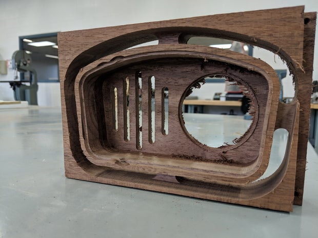
With the setup complete the first operation I ran hollowed out the space for all of the electronics.

Next, I CNC machined a small lip on the inside edge of the part. This lip will be used to attach the back of the amp to hide all of the electronics.

The slots the speaker will be installed behind and a circle where the "radio dial" goes was the next operation.

To finish off the router work I ran the last toolpath to cut the outside form of the amp. With using screws to hold the wood in place, instead of just the vacuum table, I programmed tabs into the toolpath to keep the amp design attached to the wood blank. The tabs just allow for the whole part to be kept securely in place while the router completed all its work.

Step 4: Clean Up
The CNC router left this part in rough shape. I did a little clean-up work to make it easier to work with. I held off on cutting the amp design from the tabs because it was easier to use the belt sander that way. I ran the front face of the amp across the belt sander to get rid of all the frays and burrs left over from the last step.


The rest of the amp really couldn't be sanded clean until it was removed from the stock piece. I took the part over to a bandsaw and cut it out.

I tried to cut as much of each tab off as I could to reduce the amount of sanding that I had to do. Whatever portions of the tabs that were left I took care of with the belt sander.


I finished my first round of sanding with some 80 and 120 grit sandpaper to clean up the inside edges and speaker slots.

Step 5: Solder
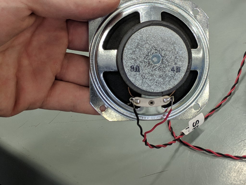
I purchased an amp kit which included all the wires, a three inch speaker, an output jack, and a potentiometer for the volume. The wires were labeled so I knew which ends needed to be soldered to which components. Before I started permanently assembling these parts together I used my helping hands to "dry" fit everything together.

After I was sure I knew where all the components were supposed to be assembled I started by soldering the wire to the speaker.
I stripped the end of the wires


and then held them in place as I soldered them to the speaker.

I moved onto the jack next. I made sure to thread the correct wires through the correct posts of the jack before soldering.


The last piece I needed to solder was the LED. The kit came with a red LED to use as an indicator to when the amp is turned on. I want to use two LEDs to backlight the faux radio dial that will be part of my design. The process isn't really any different. I'm just switching out the red LED for two white LEDs.

I really need to practice my soldering as most of these connections don't look great.
I plugged in a 9V battery and tested out the whole system. If the LEDs come on I know I did everything right.
Step 6: Testing Electronics

SUCCESS!
Step 7: Speaker Install
I should have created some version of a mock up of this idea as once I got to this stage of the project I wasn't sure I left myself enough room for all the electronics to fit. I decided to start with the biggest component that needed to be installed and that was the speaker. This was going to be placed behind the vertical slots on the housing.
The amp kit I bought came with a black metal grate piece that the speaker could be placed behind. Originally, I planned to use some type of tweed fabric like I always see in vintage radios. I didn't have any fabric like that lying around and I couldn't find any locally that I really liked. I just decided to use the metal piece that came with the kit.
The black grate was square which wouldn't fit into the space on my amp.

I used a pair of metal shears to cut it to fit.

I placed my speaker on top of the metal to mark the hole locations I needed to drill for the screws that will hold the speaker in place. When I got the speaker where I wanted it and held it up to inspect how the metal and speaker looked from the front, I noticed two things I didn't like.
First, I made the slot portion of my design too tall and the speaker didn't fully take up the space behind them. Not the biggest issue and once the back plate of the amp is installed and light isn't coming in through the back it shouldn't be a big issue.
Second, the bare metal of the speaker showed very prominently and really distracted from the overall vintage aesthetic. I remembered I had some paint markers lying around. I used the black one to turn the bare shiny metal parts to a nice black color that matched the metal.

I drilled the holes I needed with a drill press to make sure I didn't drill all the way through the wood and installed the speaker with a few brass screws.


Step 8: Faux Radio Dial
If I was more skilled and wanted to take the time I would make the radio dial portion the volume knob for my amp. That would make the amp feel more vintage and realistic, but for completion's sake I decided to make the dial portion just for show.
To make this faux radio dial insert I measured the interior diameter of the cutout circle with a dial caliper. I quickly drew a couple of circles with varying degrees of tolerance on the design software for our laser cutter and cut them out.
My goal was to cut out a disc that was tight enough that the plastic would just press fit into place. With all the electronics fitting in so tightly and some being placed over top of the acrylic I figured a press fit with no extra adhesives or mechanical holding would work fine.
One of the circles I cut out was the perfect size, so I moved onto the graphics portion of this step.
I did a quick Google search for vintage radio dials and found one I thought would look good. I printed that image out onto a darker white/yellowish cardstock. I used the acrylic disc as a template and cut out the printed image to match that size.
I thought I would just glue the dial image onto the acrylic disc and this part of the project would be done, but I didn't think it looked right. I realized the picture didn't have a pointer/indicator to show which "station" the "radio" is tuned to.
I grabbed the cardstock I used for the image and cut out a small pointer. I colored this new piece with a black marker and once I stacked up the disc, pointer, and dial image again it looked like this...

I used spray adhesive to glue all the parts together, let it dry, and popped it into place.

Step 9: Jack and Volume Install
Now that I had the radio dial made and in place I could move onto finding places inside the housing to fit the other electronics. Most importantly the jack and volume knob because both parts needed to have a hole drilled in the housing to allow them to be installed correctly.
This part of a project always stresses me out because if I mess up badly enough I have to scrap the whole thing and start over. Luckily all the mistakes I made on this project were small and I could hide them easily enough.
First up, I was going to install the volume knob on the side of the housing. I held the wood in place, took measurements, visually checked over and over, and for good measure triple and quadruple checked that where I was about to drill a hole would be correct. With all systems looking good I drilled the hole in the side for the volume knob.

And FAIL!
The hole was too close to the circle cutout for the dial insert and I couldn't get the potentiometer and the board it was on to fit properly. Luckily, with a little more drilling persuasion I was able to get the jack to fit in that spot.
Crisis. Averted.
I went ahead and took even longer finding, checking, rechecking, measuring, and remeasuring a spot on the top of the housing for the new position for my volume knob. This time I did a better job and the hole I drilled worked.
I installed the jack and volume knob in place and breathed a sigh of relief as the hardest part of this project for me was over.


The other electronics that still needed a home in that crowded space were the battery and the LEDs. With the idea of someday redoing this project and changing a few things, I chose to use hot glue to hold the remaining parts in place. Unless I'm changing the battery I'll never see the insides of this thing anyway so I'm fine with the temporary solution.
Step 10: Back Plate
Originally, I planned to make a wooden back for this amp but I ran out of the walnut I was working with. I pivoted and decided to see how a metal plate would look. I cut out a template of the back of the housing from cardboard and used that to transfer the shape to a piece of sheet metal I had on hand.
Using a combination of different metal shears I rough cut the shape out and then used a file to clean up the edges and make it fit on the back of the amp.

I drilled a hole in the center so there would be an easy way to pull off the back when the battery needs to be replaced. After everything was said and done I didn't think it looked too bad.

I'll clean the metal up and give it a clear coat before I do the final assembly. Like the radio dial this back plate is held in place with a friction fit and with a little force can be popped off. I think this should be fine as this amp won't be getting used all the time.
Step 11: Final Assembly
Before putting everything together I wanted to soften the look of the housing a little. I sanded off the sharp corners and did a once over of the outside with 150 grit and then 220 grit.

I used the proper respective clear coat sprays for both the wood and the metal back plate. When everything was dry I put all the electronics back in. This time using a little hot glue to keep the battery clip and LEDs in place. I also corralled all the wires with some zip ties to make the inside less rat nesty.

When I put the back plate on to finish things off, I completely forgot about the magnet from the speaker, which holds the plate in better than I could have hoped.

I'm a big fan of how it turned out. This was one of those projects I started where I knew I had the tools and equipment needed to make something like this. But I wasn't quite sure if I could really make it look the way I had dreamed up in my head. It is far from perfect but overall, I'm really happy with how it turned out.
You can't really see the dial light up in a fully lit room, but if you turn the lights off or down it looks just like I was hoping!

Step 12: Time to Shred!
Completely assembled, time to see if this thing actually works!
Full Disclosure: I don't really know how to play a ukulele. Also this is a shop class built electric ukulele, not sure I've ever been able to get it correctly tuned.
We will now be able to test and play ukuleles whenever they are finished. No more time crunch for us!
Plus, I now have a cool little conversation starter I can carry around to promote my classes. I just need to learn how to play the ukulele and I'll be all set!
Step 13: The End Bit
Thank you so much for checking out my project. I truly appreciate people taking time to view my work. If you were looking to build a little amp I hope this was helpful to you in some way or at the very least somewhat interesting.
If you teach shop class of some kind I've started a little website to document/compile shop teacher content/curriculum. I'm really just getting started with it but I should be posting much more to it soon. Find it at Shop Class Builds.
Find me on Instagram @shopclassbuilds
Again thank you for taking time out of your day to scan through my project!
Let me know in the comments if you make one or something similar!

Second Prize in the
Retro Tech Challenge


