

Introduction: Workholding and Offsets


It's important to determine workholding before CAM programming.
Workholding Options
The bed of the DMS is a thick acrylic sheet. It is drilled in a 6" hole pattern, with 3/8"-16 threaded brass inserts in each hole.
- Over-tightening a fastener can pull the insert out of the table.
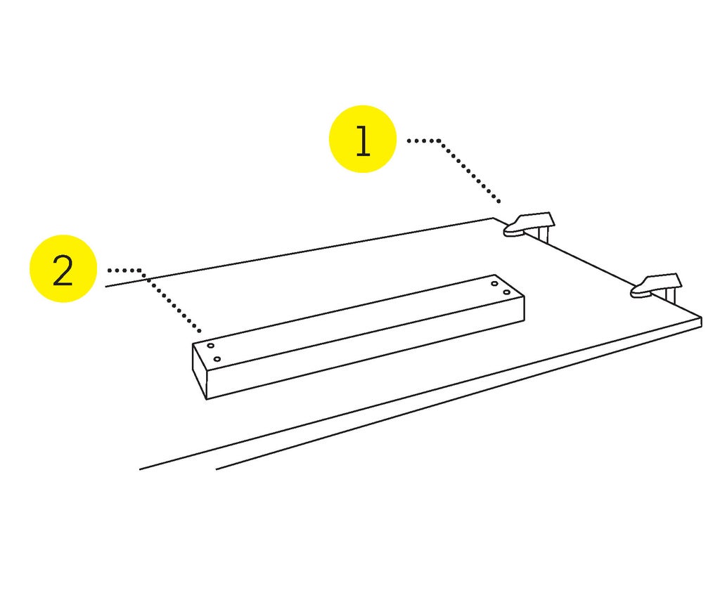
Spoiler Board & Clamps
- Clamp a spoiler board to the table.
- Screw your material to the spoiler board. Use a minimum of 4 screws, and more for large projects.
Make sure that the tool will not collide with a clamp or screw.
- Brass screws will not damage the tooling in the case of a collision.

Threaded Inserts & Step Clamps
- Hold the work with a step clamp.
- The clamp should be level.
- Support the end of the clamp with a step block.
- Insert a threaded stud through the clamp into the table insert.
- Tighten a nut on top of the clamp.
- Use a minimum of 4 clamps, and more for large projects.
Make sure that the tool will not collide with a clamp.
Double Sided Tape
- Clean the table and material.
- Tape will not stick to damp or dusty materials or MDF.
- Apply tape to your workpiece.
- Press firmly to adhere the material to the table.
- Test the adhesion before starting to cut your project.
Tape works better on short wide items than tall narrow ones.
Step 1: Establish Your Work Offset


Set the Work Offset (G54)
You must use the same Work Coordinate System (WCS) you chose in your CAM program.
You have 3 options when setting the Work Offset.
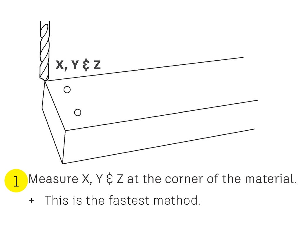
- X, Y & Z at the corner
- X & Y at the corner, Z in the middle
- Air pass
- X & Y at the corner, very high Z
Move the tool tip to Work Home
- Perform a tool change.
- Choose a drill bit or small diameter tool to make finding your WCS easier and more accurate.
- Jog the tool to Work Home.
- Press MDI. (F4)
- Type G53 & press Cycle Start.
Set X & Y at the corner
- Press ESC to go up one level.
- Press User. (F5)
- Press Load Zero Offsets. (F2)
- Press Load G54 Offsets. (F1)
- Press Clear All Offsets. (F6)
- Press Yes. (F1)
- Press Exit. (F7)
- Press Load G54. (F1)
- Press X & Y. (F1) & (F2)
- The status for each axis will change to loaded.
- Press Exit three times. (F7)
- This will return you to jog mode.
You have set your Work Coordinates for X & Y. Now, you must decide where to set your Z axis.
Step 2: Set the Z Work Coordinate
Reposition and set Z
The following steps will set Z, and also enable the machine to calculate exactly where the tool tip is located, even when moving the B & C axis.
- If needed, jog the machine to where you want to set Z.
- Press MDI. (F4)
- Type G48S0 (zero, not the letter) & press Cycle Start.
- Type G53 & press Cycle Start.
- Type D[tool number] & press Cycle Start.
- Type G48S1 & press Cycle Start.
- Press ESC.
- You should be at the jog menu.
- Press User. (F5)
- Press Load Zero Offsets. (F2)
- Press Load G54. (F1)
- Press Z. (F3)
- This will set your Z offset.
Confirm that your WCS has been correctly set.
- Press Exit (F7) 3 times.
- Press MDI. (F4)
- Take a photo of the screen.
- Include the X, Y & Z values.
- This will allow you to return to Work Home in the case of a problem.
- Type G54 & press Cycle Start.
- Check values of X, Y & Z.
- Z should be 0.
- X & Y will be 0, unless you jogged the machine to set Z.


