

Introduction: DIY Professional 18650 Battery Pack


The world is shifting away from fossil fuels and will one day become fully electric. In the present world, Lithium-ion is the most promising chemistry of all batteries. Most of the battery packs used in Laptops, RC Toys, Drones, Medical devices, Power tools, e-bikes, and electric cars (EV) are based on 18650 batteries. It is one of the most mature Li-ion formats available, is produced in high volume, and enjoys a low cost per Wh.
My Book : DIY Off-Grid Solar Power for Everyone
You can order my Book on Off-Grid Solar Power from Amazon
Support me On Patreon:
If you enjoy my work here on Instructables, consider joining my Patreon, it will be a great help for me to make more interesting projects in the future.
Patreon Link: https://www.patreon.com/opengreenenergy
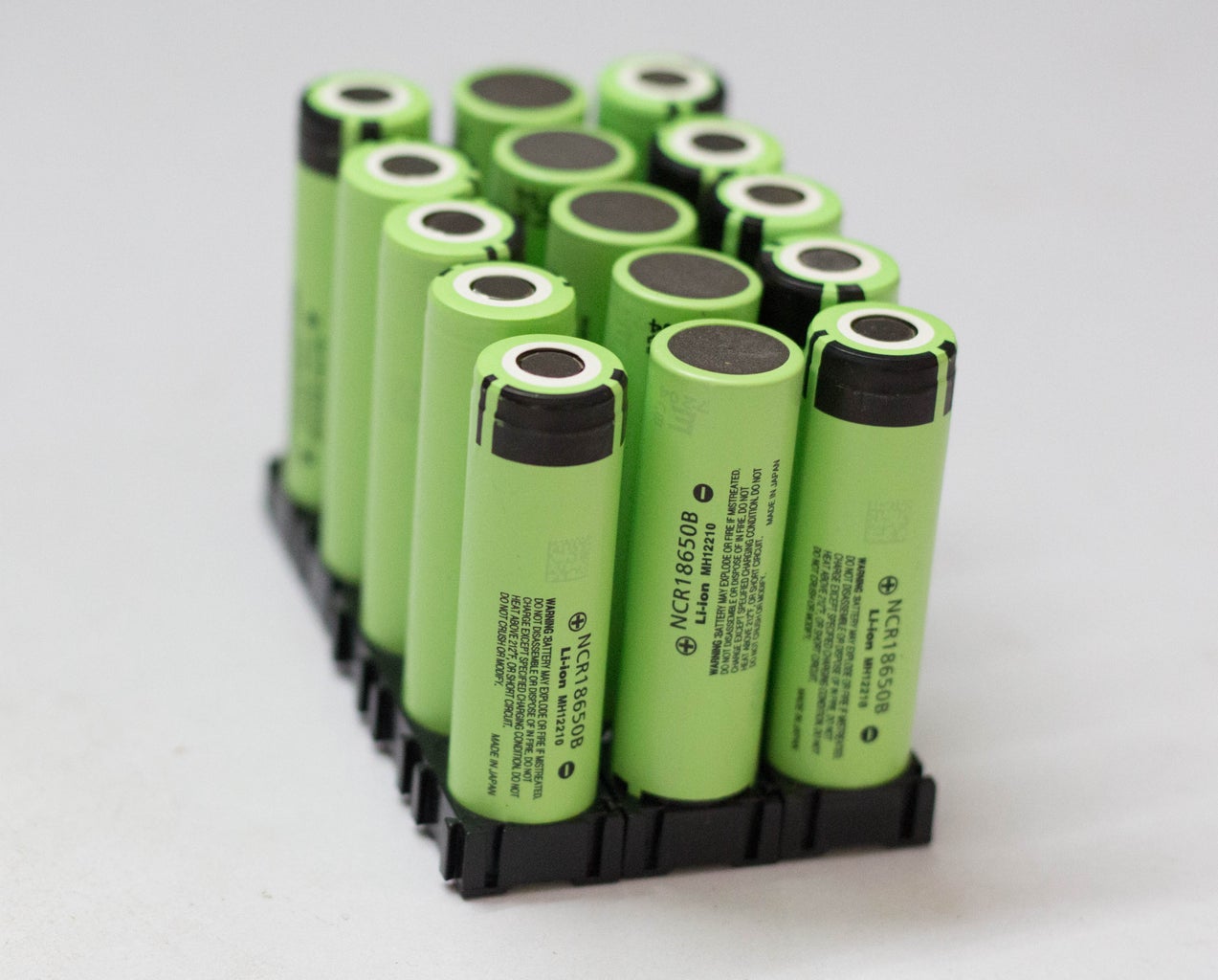
The 18650 (18mm diameter and 65mm length ) battery is a size classification of lithium-ion batteries. It is the same shape, but a bit larger than a AA battery. AA batteries, by comparison, are sometimes called 14500 batteries because they have a 14mm diameter and 50mm height.
Earlier I have made a Solar Power Generator which is working really nice till now. But the main problem is its weight, it is really heavy. The main weight of the Solar Generator is due to the heavy lead-acid battery inside it. So I decided to make a light and compact 18650 Li-Ion Battery Pack.
In this Instructable, I will show you, how to make a 18650 battery pack for applications like Power Bank, Solar Generator, e-Bike, Power wall etc. The fundamental is very simple: Just to combined the number of 18650 cells in series and parallel to make a bigger pack and finally to ensue safety adding a BMS to it.
At the end of this project, I made a custom 3D printed enclosure for the battery pack.
Disclaimer:I cannot be held responsible for any loss of property, damage, or loss of life if it comes to that. This tutorial was written for those who have knowledge of rechargeable lithium-ion technology. Please do not attempt this if you are a novice. Stay Safe.
Step 1: Parts and Tools Required
Parts Required:
1. 18650 Battery ( GearBest / Amazon )
3. Ni Strips ( Banggood / Amazon )
4. Battery Level Indicator ( Banggood )
5. Rocker Switch ( Aliexpress / Banggood )
6. DC Jack ( Banggood /Aliexpress )
7. 18650 Battery Holder ( Banggood )
8. 3M x 10mm Screws (Banggood / Aliexpress )
Tools Used
1. Spot Welder ( Banggood /Amazon)
2. 3D Printer (Creality CR10S )
2. Wire Stripper/ Cutter ( Amazon )
3. Hot Air Blower ( GearBest )
3. Multimeter ( Amazon )
5. Li Ion Charger ( GearBest )
Safety Equipment :
1. Safety Googles ( Amazon )
2. Electrical Gloves ( Amazon)
Step 2: Selecting the Right 18650 Cells for the Battery Pack


You will find many types of 18650 cells in the market in the price range of $1 to $10, but which are the best? I will highly recommend buying 18650 cells from branded companies like Panasonic, Samsung, Sanyo, and LG. These cells that have well-documented performance characteristics and excellent quality control. Reputed brand 18650 cells are generally costly, but if you consider for long time use then they are worth having it.
Don't buy any cells with the word FIRE in the name like Ultrafire, Surefire, and Trustfire. In reality, these cells are just factory rejects, purchased by companies like Ultrafire and repackaged in their own branded cover. Many used batteries are rewrapped as new and white-labeled. They sell the battery by marking capacity up to 5000mAh, but in actual their capacity is between 1000 to 2000 mAh. Another major problem with these cheap 18650 cells is the high risk of explosion when overheated during the charging or discharging.
In this project, I have used green Panasonic 18650B cells of capacity 3400 mAh from GearBest.
Step 3: Choosing the Right Battery Strips

To make the battery pack, you have to connect the 18650 cells together by means of Nickel strips or thick wire. Generally, Nickel strips are widely used for this. In general two types of nickel, strips are available in the market: nickel-plated steel strips and pure nickel strips. I will suggest buying a pure nickel. It is a little bit costlier than nickel-plated steel, but it has much lower resistance. Low resistance means, less heat generation during the charging and discharging, which leads to longer useful battery life.
Nickel strips come with different dimensions and lengths. Choose the strips according to the current rating.
Step 4: Spot Welding Vs Soldering

You have two options two connect the 18650 cells together: 1. Soldering 2. Spot Welding
The best choice is always Spot welding, but Spot Welder is much costlier than a good quality Soldering Iron.
Soldering :
You should know why Spot welding is preferred over soldering, the problem with soldering is that you apply a lot of heat to the cell and it doesn’t dissipate very quickly. This enhances the chemical reaction in the cell which damages the cell's performance. Ultimately you will lose some capacity and life the cells.
But if you are not interested to buy a costly Spot Welder, you can solder the nickel tabs to the cell by following some precaution and tricks :
1. To minimize the contact time of your soldering iron on the cell, make sure the surface is scuffed up sufficiently and you use plenty of flux to allow for fast solder flow.
2. It is better to have a good quality high wattage ( min 80W ) iron with good thermal capacity so it can deliver the heat to the joint quickly so you don't have to hold the iron to the battery for ages and let the heat seep into it, causing damage to the battery.
Spot Welding :
The reason we spot weld because it securely joins the cells together without adding much heat to them. There are two grades of spot welders currently available in the market: hobby grade and professional grade. A decent hobby-grade Spot welder costs around $200 to $300, whereas a good professional grade may cost around ten times more. So I will suggest buying a hobby-grade spot welder from any online store like Banggood, Aliexpress, or eBay.I am using the SUNKKO 709A 1.9kw Spot Welderfrom Banggood.
Step 5: Check the Cell Voltage


Before connecting the cells in parallel, first, check the individual cell voltages. For paralleling the cells, the voltage of each cell should be near to each other, otherwise, a high amount of current will flow from the cell with a higher voltage to the cell with a lower voltage. This can damage the cells and even result in fire on rare occasions.
If you are using brand new cells, the cell voltage is near 3.5 V to 3.7 V, you can join them together without worrying much. But if you are going to use an old laptop battery, be sure the cell's voltage is nearly the same, otherwise, charge the cells to the same voltage level by using a good Li-Ion Battery Charger. I used my Nitecore SC4 Charger to charge all the 18650 cells before joining them together.
Step 6: Battery Pack Capacity and Voltage

To make the battery pack, you have to first finalize the nominal voltage and capacity of the pack. Either it will be in terms of Volt, mAh/ Ah, or Wh. You have to connect the cells in parallel to reach the desired capacity (mAh ) and connect such parallel group in series to achieve the nominal voltage (Volt ).
For this project let the requirement is: 11.1 V and 17 Ah Battery Pack
Specification of 18650 Cells Used: 3.7V and 3400 mAh
Capacity (mAh):
The desired capacity of the battery pack = 17 AH or 17000 mAh.
The capacity of each cell = 3400 mAh
No of cells required for parallel connection = 17000 / 3400 = 5 nos
Commonly cells in parallel are abbreviated in terms of ‘P’, so this pack will be known as a “5P pack”.When 5 cells are connected in parallel, ultimately you made a single cell with higher capacity ( i.e 4.2V, 17000 mAh )
Voltage(Volt) :
The desired nominal voltage of the battery pack is 11.1V.
The nominal voltage of each cell = 3.7 V
No of cells required for series connection = 11.1 /3.7 = 3 nos
Commonly cells in series are abbreviated in terms of ‘S’, so this pack will be known as a “3S pack”.
So we have to connect the 3 parallel groups (5 cells in each group ) in series to make the battery pack.
The final pack configuration is designated as a “3S5P pack” with a final specification of 11.1V,17AH.
Step 7: Assemble the 18650 Cells


From the previous step, it is clear that our battery pack is made up of 3 parallel groups connected in series ( 3 x 3.7V = 11.1V ), and each parallel group has 5 cells ( 3400 mAh x 5 = 17000 mAh). Now we have to arrange the 15 cells properly for making the electrical connection among them and with the BMS board.
Place the first parallel group of cells (5 nos) positive side up, then place the second parallel group negative side up, and then finally the last parallel group positive side up. For better understanding, you can see the above picture.
You can assemble the cells to make the pack by using hot glue or by using a plastic 18650 battery holder. I used plastic 18650 cell holders/spacers to assemble the 15 cells. The main advantages of using these cell holders are
1. You can make a custom pack of any size according to your requirement.It's like solving a puzzle.
2. It provides space between the cells, which allow fresh air to pass and the battery gets cooled easily.
3. It makes your battery pack solid and reliable.
4. It provides safety anti-vibration to your battery pack
Step 8: Spot Weld the Nickel Strips


Now it is time to know the procedure for using the Spot Welder ( I am talking about the Spot welder that I have used in this project). The Spot welder has three welding choices: fixed welding head, fixed welding head with foot switch, movable spot welding pen with the footswitch. I prefer to use the second option. Before welding, you have to prepare the nickel strips and welder.
Cut the nickel strips :
Lay your nickel strip on top of the 5 cells ( parallel ), ensuring that it covers all cells terminals, leave 10mm excess strips for connecting it to the BMS, and then cut it. For series connection cut small nickel strips as shown in the figure. You will need four long strips for parallel connection and 10 small strips for series connections.
Connect the first parallel group negative terminal to the positive terminal of the second group and then the negative terminal of the second group to the positive terminal of the third group.
Weld the Battery Strips :
This spot welder can be used to weld the pure nickel as well as nickel-plated steel strips. You have to adjust the welder pulse and current knob according to the thickness of the nickel strips.
For 0.15 mm nickel strips, press the pulse knob 4P and current knob to 4-5. Similarly for 0.2 mm nickel strip, press the pulse knob 4P,6P, and current knob to 7-8. Make sure the welding pen is compressed with the nickel strip and battery terminal, then press the footswitch. You will notice a small spark and two-dot mark on the strip.
Successful Welding :
You can check the weld quality by pulling on the nickel strip. If it doesn’t come off with hand pressure or requires a lot of strength, then it’s a good weld. If you can easily peel it off, then you have to increase the current.
Safety: Before starting the spot welding, always wear safety goggles.
Step 9: Adding the BMS


A battery management system (BMS) is an electronic system that manages a lithium battery pack and the main functionalities are
1. Monitors all of the parallel groups in the battery pack and disconnect it from the input power source when fully charged ( near 4.2V )
2. Balance all the cells voltage equally
3. Doesn't allow the pack from over-discharged.
The two important parameters required to buy a BMS are: i) Number of cells in series - like 2S / 3S / 4S
ii). Maximum discharge Current - like 10A/ 20A /25A /30A
For this project, I have used a 3S and 25A BMS board. These are the specifications of that BMS :
Overvoltage range: 4.25~4.35V ± 0.05V
Over-discharge voltage range: 2.3~3.0V ± 0.05V
Maximum operating current: 0~25A
Working temperature: -40℃ ~ +50℃
How to Connect?
Connect the BMS as shown in the wiring diagram. The BMS has four soldering pads: B-, B1, B2, and B+. You have to connect the first parallel group negative terminal bus to the B- and positive terminal bus to the B1. Similarly the third parallel group negative terminal bus to the B2 and positive terminal bus to the B+.
You can spot weld the nickel strips to the BMS or solder it to the PCB pad. I preferred to solder the nickel strips to the PCB for a sturdy connection. First, apply soldering flux to the PCB pads and end of the nickel strips. After that tin all the pads by applying a little amount of solder and then solder them together.
Credit: The wiring diagram is taken from the Banggood product page.
Step 10: 3D Printed Enclosure


The battery pack has all-around exposed nickel strips, to avoid any accidental shorting, I designed an enclosure for it. I used Autodesk Fusion 360 to design the enclosure for my battery pack. The enclosure has two parts: The main Body and top lid. You can download the.STL files from Thingiverse.
I used my Creality CR-10S 3D printer and 1.75 mm green PLA filament to print the parts. It took me about 6.5 hours to print the main body and around 1.2 hours to print the top lid.
My settings are:
Print Speed: 70 mm/s Layer
Height : 0.3
Fill Density: 100%
Extruder Temperature: 205 deg C
Bed Temp: 65 deg C
Step 11: Wiring the Components


Normally a standard battery has only two terminal for connecting the load and to charge the battery. Apart from this, I have added a battery level indicator, to see the battery level whenever required. I have used a 5mm DC jack ( 12V /3A ) for input/output, 3S battery level indicator module to see the battery status, and a rocker switch to ON/OFF the battery level indicator.
Now let's move on to the wiring of the components. I've prepared this simple wiring diagram for all the components. It's pretty simple! To insulate the conductive parts, I used heat shrink tubing.
Note: Don't solder the wires ( P+ and P- ) to the BMS before installing the components into the enclosure.
Step 12: Final Assembling


First, install the components into the respective slots in the 3D printed enclosure. You can see the above picture.
Solder the positive (red wire ) from the DC jack and Rocker switch to the P+ of the BMS, negative wires from the DC jack, and Battery level indicator to the P- of BMS.
Then apply hot glue at the base of the battery compartment, then secure the battery pack. So that it will seats firmly and prevent any loss of wire connections.
Finally, screw the top lids in place! I used 3M x 10 screws for securing the lid. Now the battery pack is ready to use.
Charging the Battery Pack :
You can charge the battery pack by a 12.6V DC adapter like this. You can get it easily from aliexpress or eBay.
Hope you enjoyed reading about my project as much as I have enjoyed building it. If you’re thinking about making your own I would encourage you to do so, you will learn a lot. If you have any suggestions for improvements, please comment below.
Thanks!

Participated in the
Workshop Hacks Challenge 2017

Participated in the
LED Contest 2017

Participated in the
Metal Contest 2017


