

Introduction: DIY Wireless Charging Power Bank


As Phones get smarter and come packed with a heavier processor, it gives us a great performance, but the only down side to this is the battery life. While in intensive use the Phones may provide only a few hours of battery life, fortunately there is a wide range of power banks which are capable of charging your phone three to five times.
But when it comes to wireless charging, there are only a few power banks that offer that and are relatively quite expensive, so in this instructable I'm going to show you how to build your own Wireless charging power bank, that can charge your phone and other wearable devices.
You can also video a video on how to build this project.
Step 1: Tools and Components


Here is a list of the components and tools required, the list is simple and all you need is -
- Three 3.7V Li-ion Battery (18650)
- Boost Converter XL6009
- TP4056 Li-ion battery charger
- USB Port
- PCB
- Connecting Wires
- LEDs
Tools Required
- Soldering Iron
- Multimeter (Optional)
- 3D Printer (Optional)
Step 2: Li-ion Batteries


The main component in this project is the batteries, I have used the 18650 batteries which I salvaged from an old laptop battery pack, there are usually 6 of these in a battery pack and for this project you will need four. The batteries which I found were rated at 2200mAH and I am using three of them in parallel which would give me 6600mAH.
I soldered wires directly to all the batteries and connected them in parallel, i.e positive to positive and negative to negative. In the end, I left out some extra wire to connect to the Boost converter.
Note - If you have a hard time soldering the batteries use a sand paper to rough out both the terminals this will make soldering a lot easier.
Step 3: Boost Converter


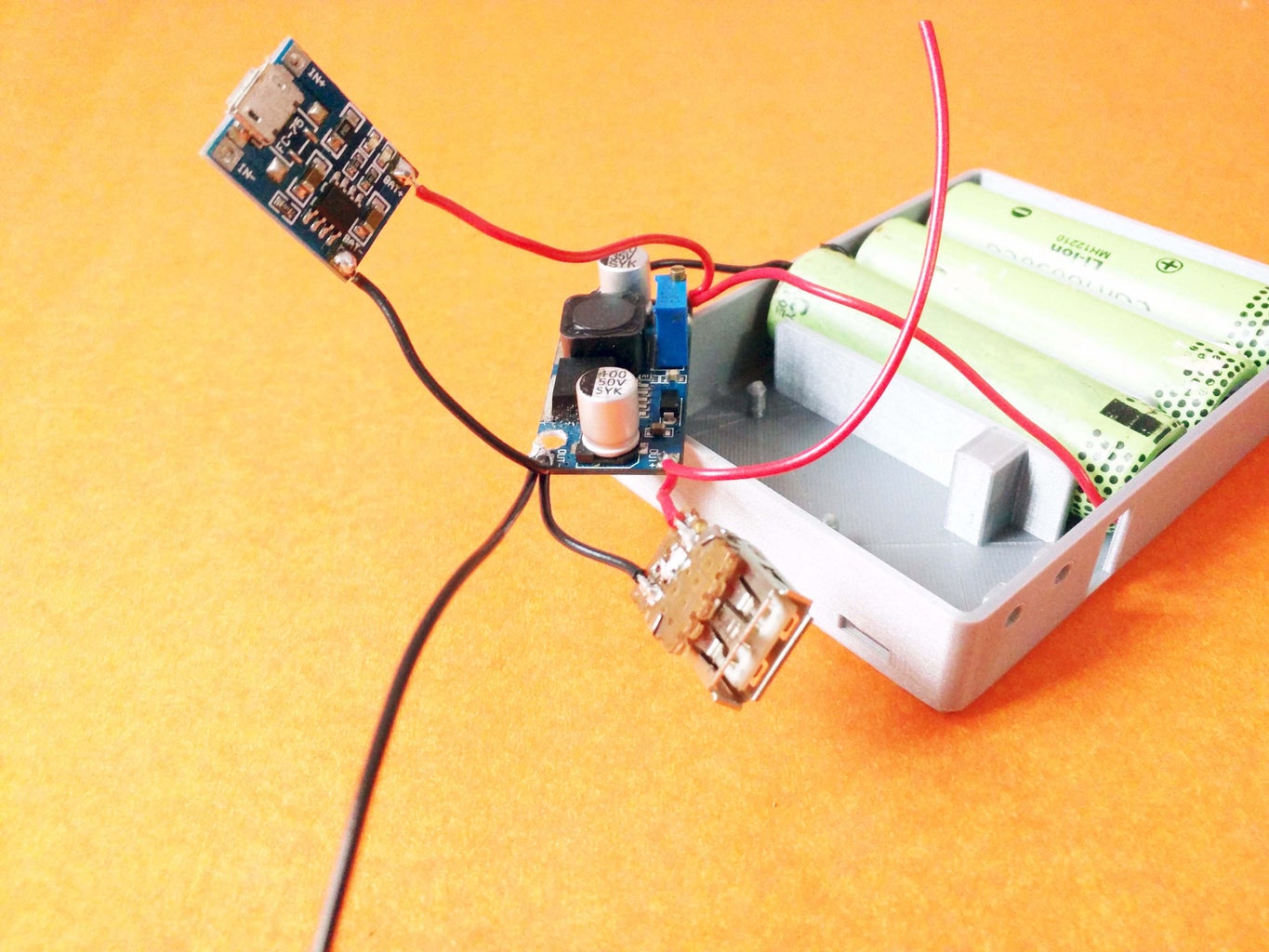
After you have connected all the batteries in parallel you should be able to measure a voltage of about 3.7V. But a phone requires 5V to charge it, to step up the voltage from 3.7 to 5V we can use a Boost converter. For this project we will be using the XL6009 boost converter, which you can purchase one at a hardware store or on EBay.
The positive terminals of the batteries should be connected the positive input terminal of the Boost converter and the negative input to the negative input terminal of the Boost converter. Once the connection is complete, use a multimeter to measure the output voltage and vary the on board pot until you have 5V across the output terminals.
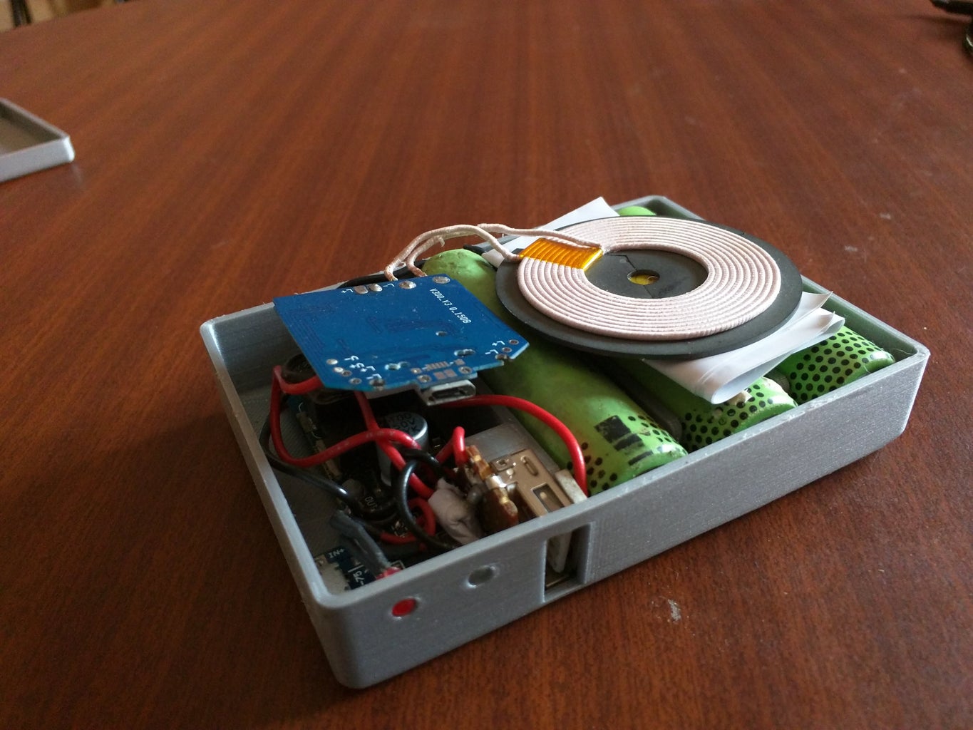
Step 4: Wireless Charging
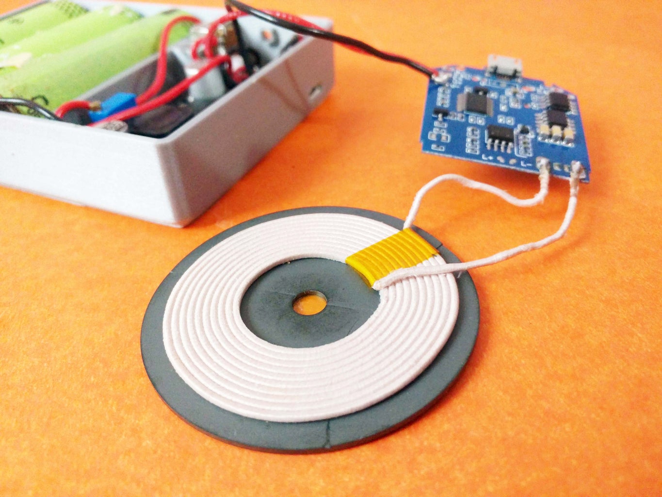
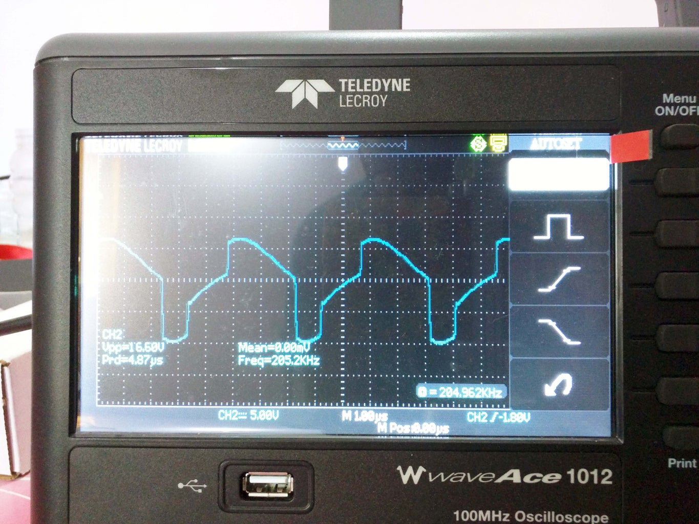

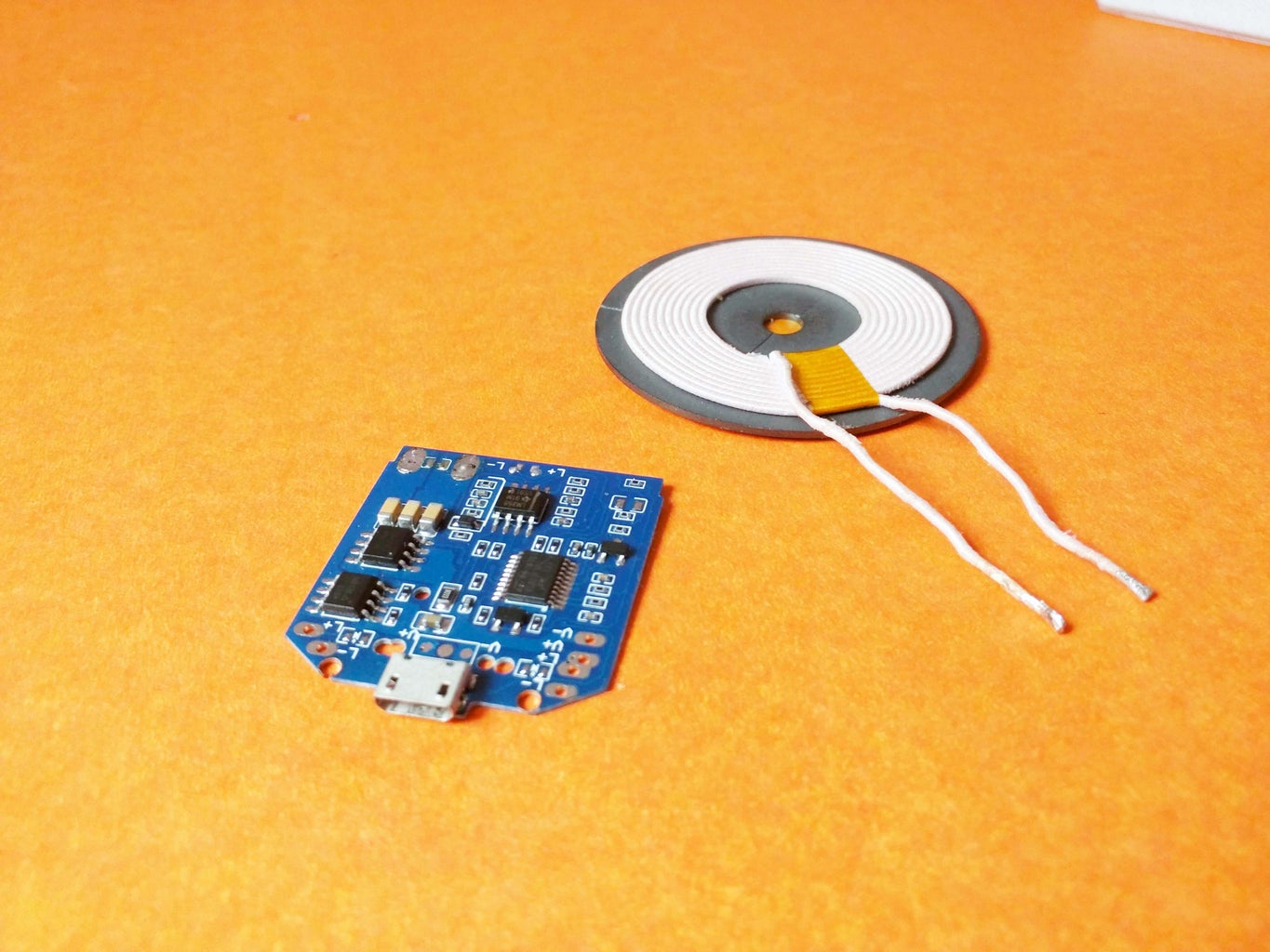

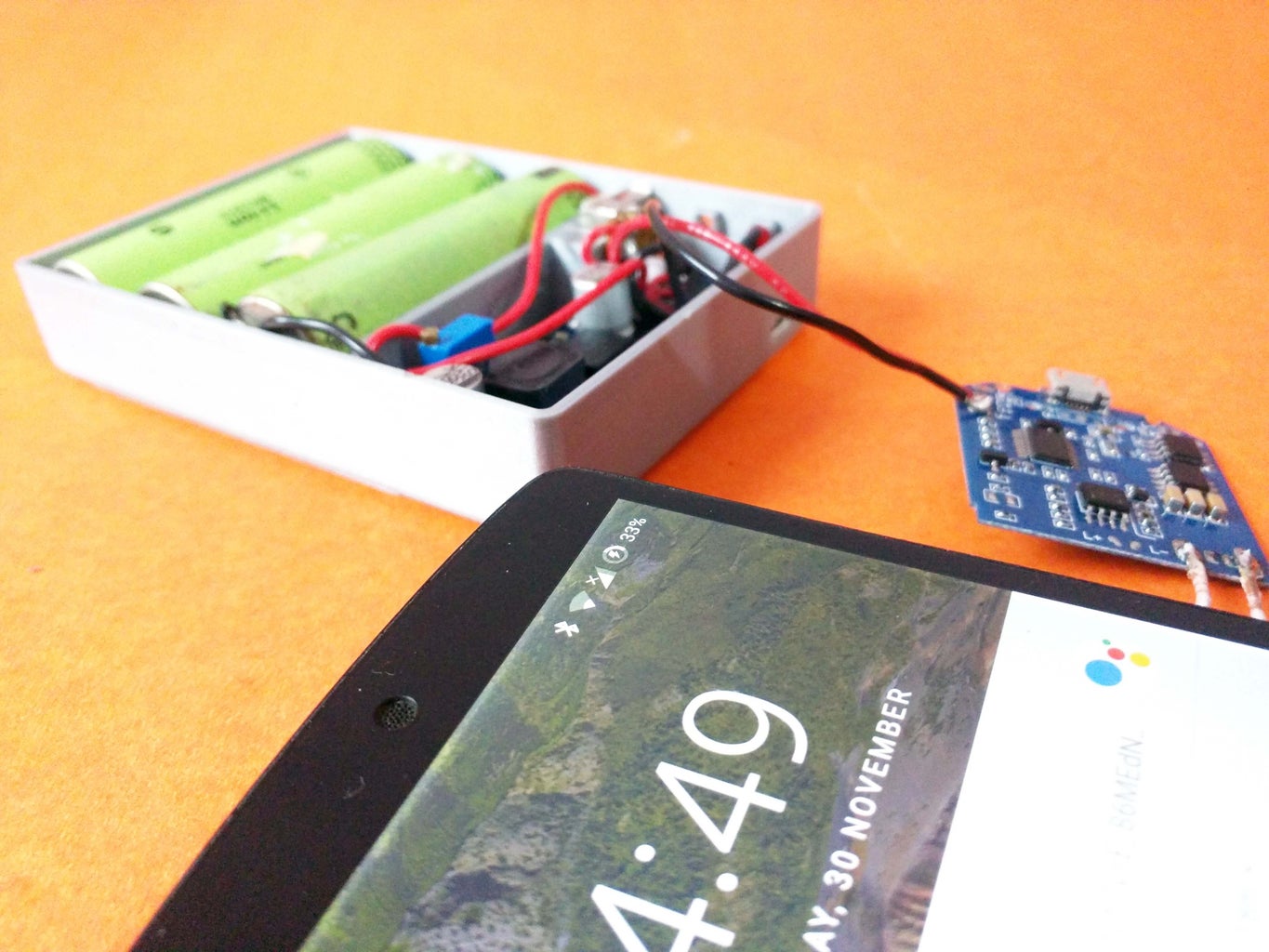
For the wireless charging part of the project I'm using one circuit which I bought from EBay. Make sure the one you purchase has a feature, that turns on the coil only when a mobile phone or any wireless charging device is placed on it. I connected mine to an Oscilloscope and notice that the circuit Which I had sent a sine wave with a peak to peak voltage of about 16V and at a frequency of 205kHz when a mobile is placed on the coil and when there is no mobile on the coil it sends a short sine wave every few seconds to check for the phone.
This saves the battery rather than continuously generating a sine wave, furthermore the circuit has a coil with a ferrite back this improves the efficiency of the overall circuit and charges when a mobile phone is placed on the opposite side of the ferrite plate.
Step 5: USB Port


I also needed a USB output port to charge devices without wireless charging, the USB port is connected in parallel to the wireless charging circuit and hence gets the same 5V. The positive terminal is connected to the VCC pin of the USB port which is the right most pin when the USB port output is facing towards you. The opposite end is the GND port which needs to be connected to the negative terminal of the boost converter output.
At this stage your USB circuit is done, plug in your phone cable and give it a try. If your phone is charging slowly then you can enable fast charge by soldering the middle two pins of the USB port together, this will enable your phone to charge much faster.
Step 6: Li-ion Battery Charger
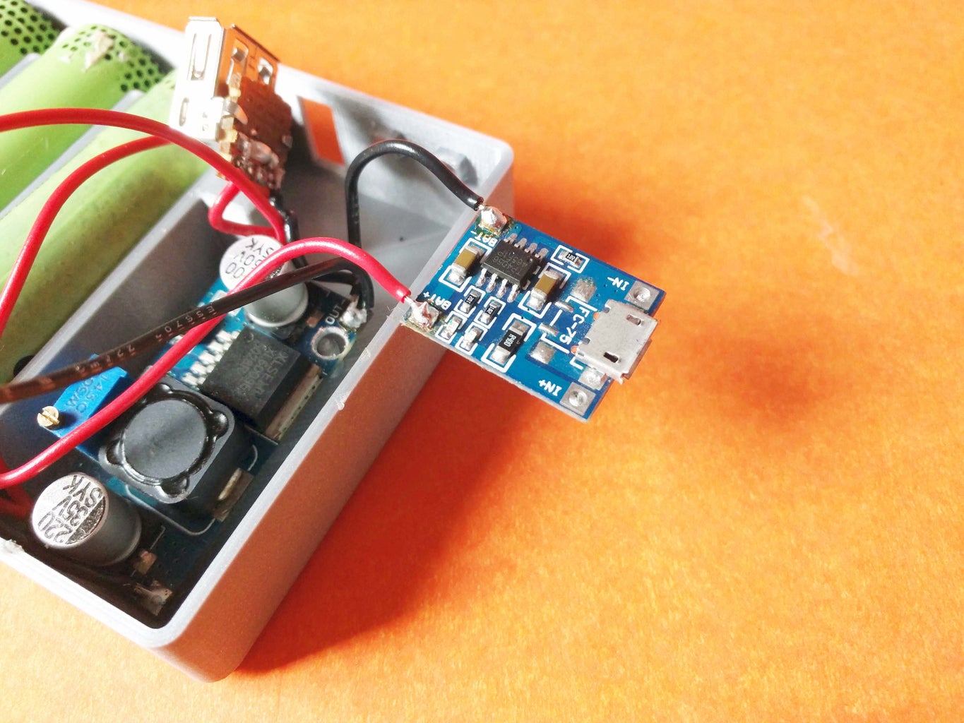


Now its time to check all the components are working fine test out the wireless charging by placing a phone on it and the USB port by plunging a phone to it. If everything works fine now it is time to add the part of the circuit which charges the Li-ion battery. There are a variety of charging circuits online, but the most common one is the TP4056 based charging circuit which features overcharging protection and has LEDs which indicate when the batteries are charging and when it is complete. This circuit charges the Li-ion batteries by connecting an 5v source to the micro USB port of the device, so any standard mobile phone charger should be able to charge the power bank. I de-soldered the onboard LEDs of the circuit and soldered the regular 3mm LEDs to the terminals which I will later plug into the 3D printed case.
Step 7: 3D Printed Case

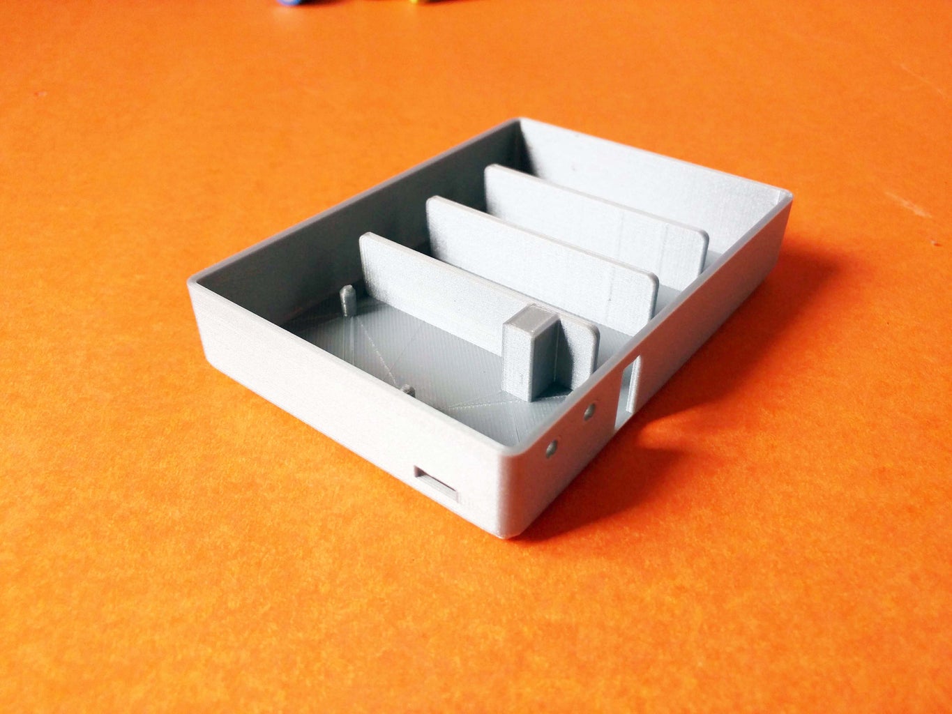


Now that the complete circuit is completed it is time to put it in an enclosure, I designed an enclosure in fusion 360 which I later printed using an ultimaker 3D printer. The files can be found in the link below and the printer settings I used are as follows.
- Printer - Ultimaker 2+
- Infill - 20%
- Filament - PLA
- Layer Height - 0.1mm
3D Printing Files - https://www.thingiverse.com/thing:2699169
Step 8: Finishing
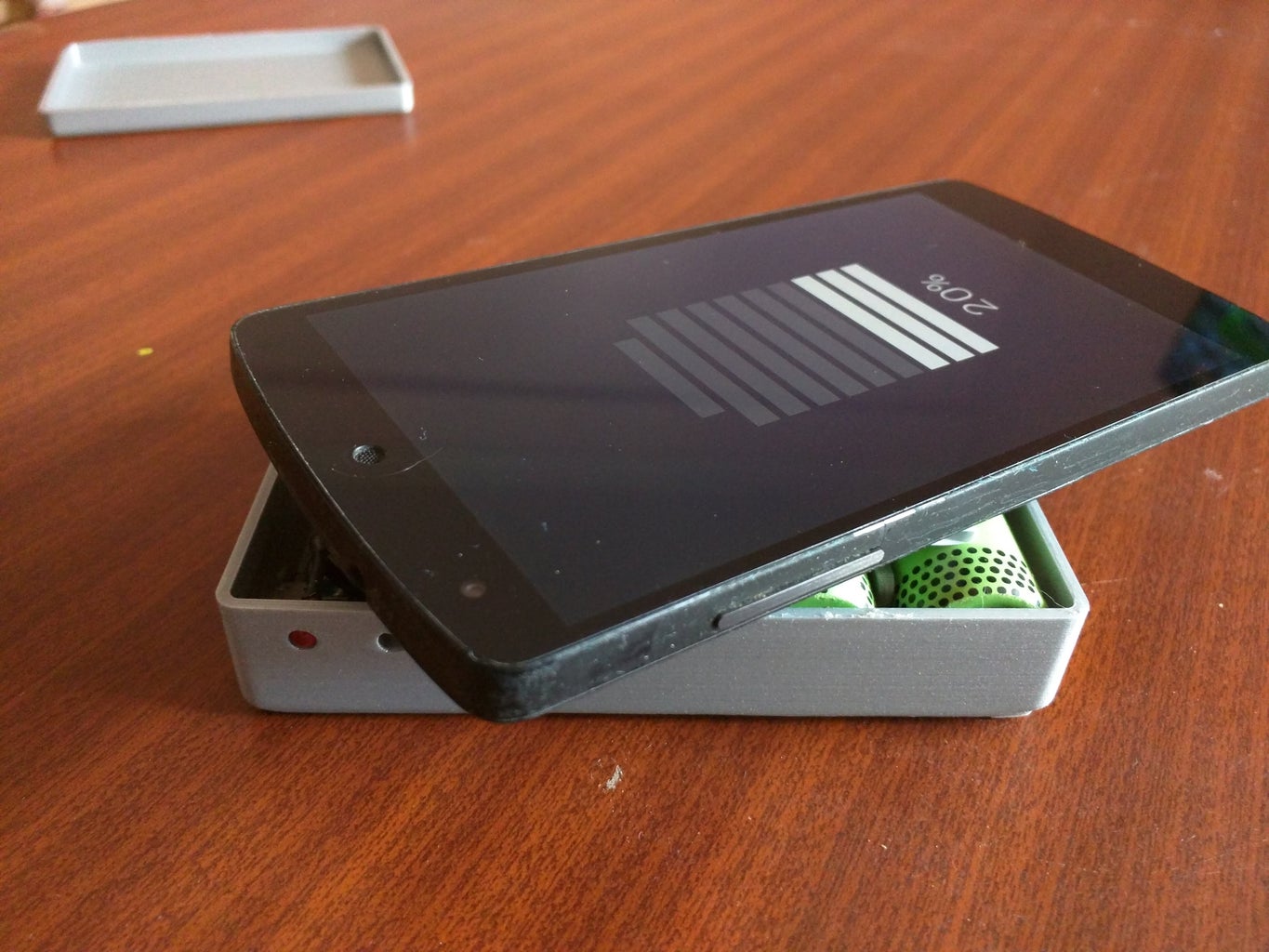

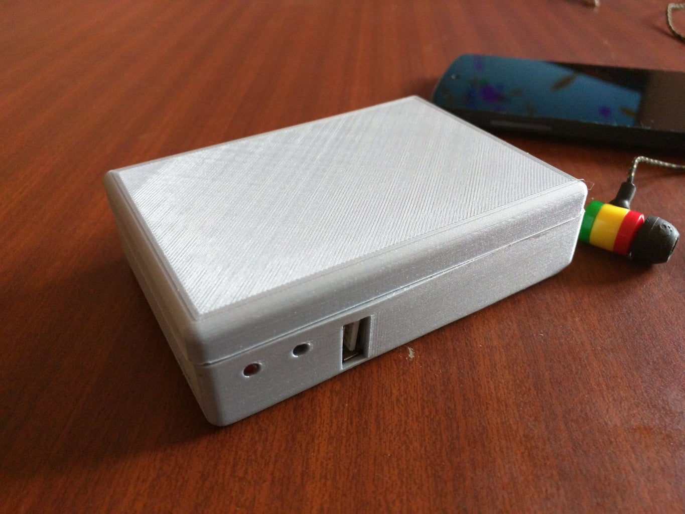
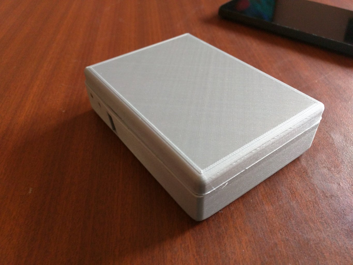
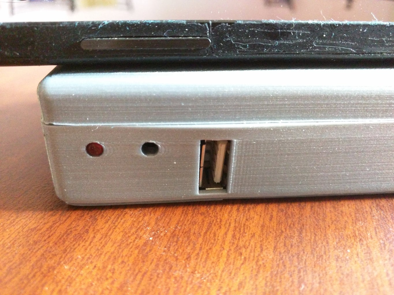
After printing the case put all the components together, make sure you are covering any uninsulated wire terminals using electrical tape and use hot glue to hold the components in place. After placing all the components in the case you should have a power bank that looks like the one in the image.
Now you have a power bank ready to be used and you don't have to worry about charging your phone or wearables anymore, you can plug it into this to get the extra few charges.

Runner Up in the
Wireless Contest


